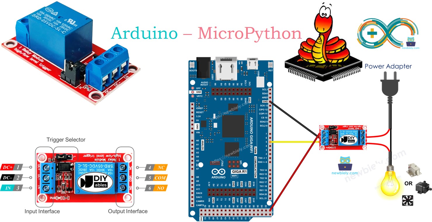
Arduino MicroPython Relay
This tutorial teaches you how to use an Arduino and MicroPython to control a relay module. Specifically, we will learn:
- How a relay works.
- How to connect a relay to a high-voltage device.
- How to connect the Arduino to the relay.
- How to write MicroPython code for the Arduino to control the relay, allowing you to switch high-voltage devices on and off.
- At the end, we will learn about LOW level trigger, HIGH level trigger, normally open mode, and normally closed mode.
Hardware Preparation
Or you can buy the following kits:
| 1 | × | DIYables Sensor Kit (18 sensors/displays) |
Additionally, some of these links are for products from our own brand, DIYables .
Overview of Relay
A relay is a programmable switch that can be controlled by an Arduino or other microcontrollers. It allows automated control of devices, especially those that operate with high voltage or high current, by turning them on or off. In essence, the relay serves as a bridge between the Arduino and high-voltage devices.
WARNING
Safety is essential when working with electricity, so be cautious to avoid electric shocks. If you are unsure about anything, seek assistance from someone experienced.
We recommend using a DC device (up to 24V) for testing purposes, even though many relays are compatible with both DC and AC devices.
Relay Pinout
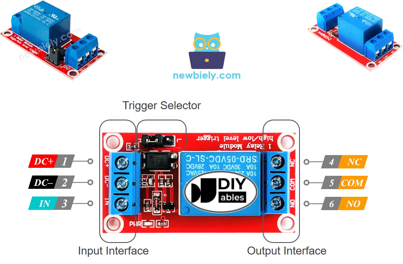
A relay has two groups of pins: input pins, which interfaces with low voltage, and output pins, which interfaces with high voltage.
- Input Pins: Connect these to the Arduino. There are three input pins:
- DC- pin: Connect to GND (0V).
- DC+ pin: Connect to VCC (5V).
- IN pin: Connect this pin to receive the control signal from the Arduino.
- Output Pins: Connect these to the high-voltage device. These pins are typically arranged in a screw terminal, and there are three:
- COM pin: Common connection used in both the normally open (NO) and normally closed (NC) modes.
- NO pin: Normally open pin. Use this in the normally open setting.
- NC pin: Normally closed pin. Use this in the normally closed setting.
- Normally Open Mode: Connect the COM pin and the NO pin.
- Normally Closed Mode: Connect the COM pin and the NC pin.
- Connect the pin on the Arduino to the IN pin on the relay.
- Set the pin to LOW or HIGH to control the relay.
Usually, only two of the output pins are used, depending on the mode:
If the relay supports both LOW level trigger and HIGH level trigger, there is typically a jumper to select either the LOW level trigger or the HIGH level trigger.
We will cover the details of LOW level trigger, HIGH level trigger, normally open mode, and normally closed mode at the end of this tutorial. To keep things simple initially, we will use the HIGH level trigger and normally open mode.
※ NOTE THAT:
Different manufacturers may arrange the pins on the relay module in various ways. Always carefully check the labels on your relay to ensure the correct pin connections. Be attentive to the pin placements!
How to Connect the High Voltage Device to Relay
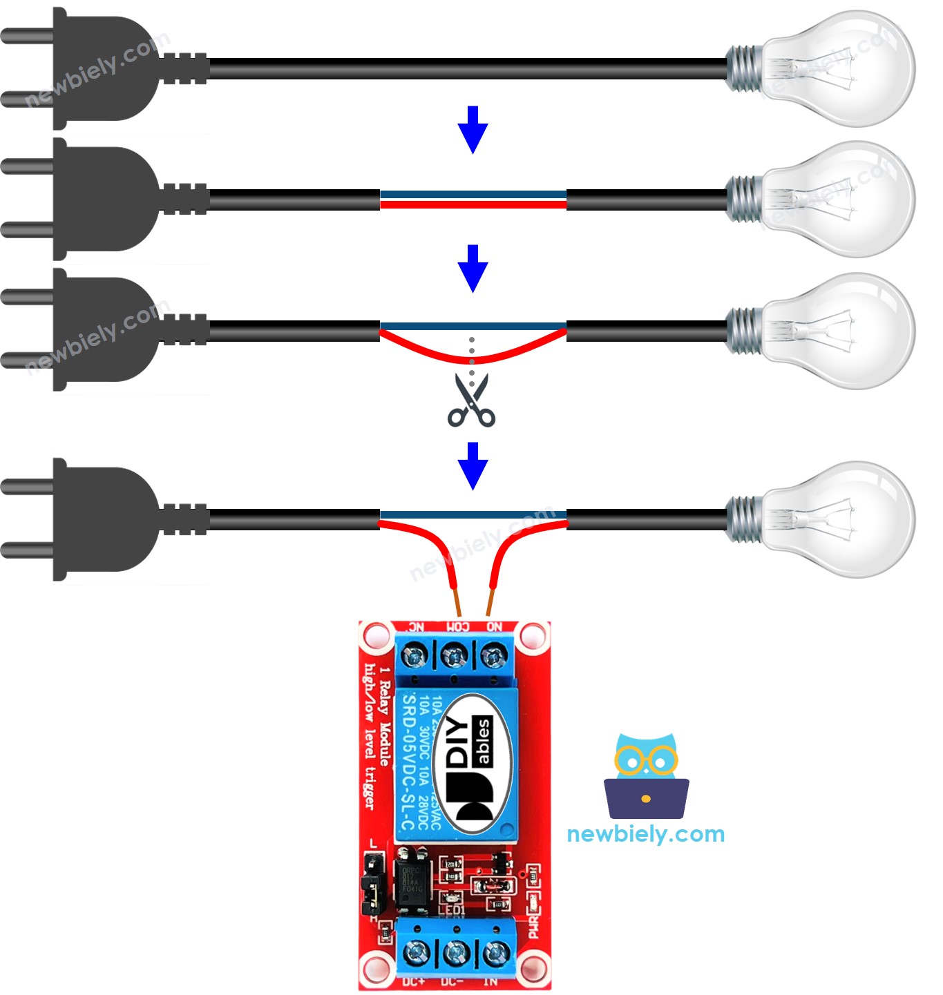
Arduino - Relay
The Arduino uses a relay to manage a device that works with high voltage.
Controlling a relay is simple. We only need:
Wiring Diagram
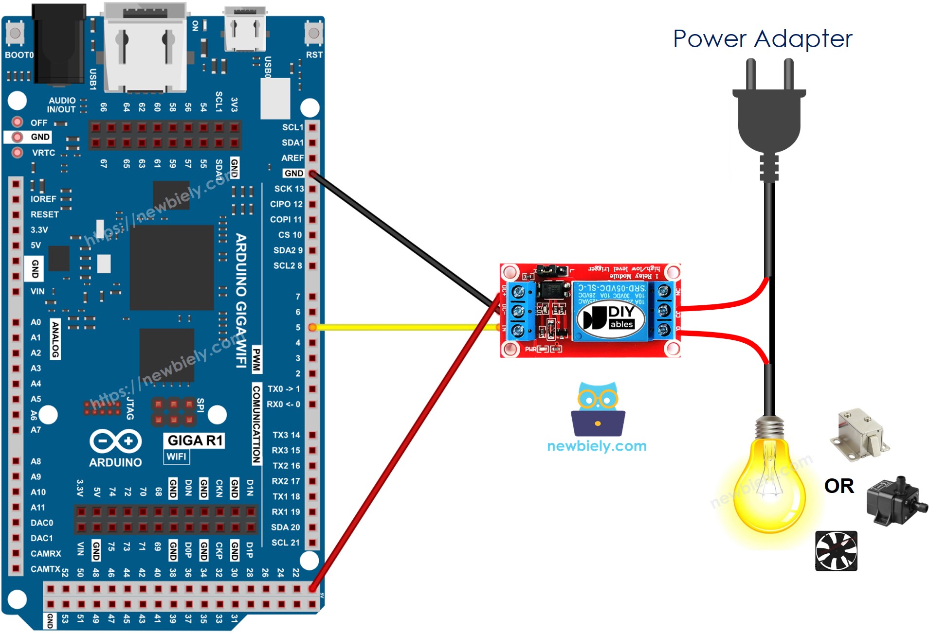
This image is created using Fritzing. Click to enlarge image
How To Program For Relay
- To configure a Arduino pin as a digital output. For example, to set up pin 3, use this function.
- Turn on relay.
- Turn off relay.
Arduino MicroPython Code
Detailed Instructions
Here’s instructions on how to run the above MicroPython code on Arduino with Thonny IDE:
- Make sure Thonny IDE is installed on your computer.
- Make sure MicroPython firmware is installed on your Arduino board.
- If you are new to Arduino with MicroPython, see the Getting Started with Arduino and MicroPython.
- Connect the Arduino board to the relay according to the provided diagram.
- Connect the Arduino board to your computer with a USB cable.
- Open Thonny IDE and go to Tools Options.
- Under the Interpreter tab, select MicroPython (generic) from the dropdown menu.
- Select the COM port corresponding to your Arduino board (e.g., COM33 on Windows or /dev/ttyACM0 on Linux).
- Copy the provided MicroPython code and paste it into Thonny\'s editor.
- Save the MicroPython code to your Arduino by:
- Clicking the Save button or pressing Ctrl+S.
- In the save dialog, choose MicroPython device and name the file main.py.
- Click the green Run button (or press F5) to execute the code.
- Check out the relay state.
Video Tutorial
Advanced Use: How Relay Works
Depending on the manufacturer and the user's setup, a relay can operate differently.
Input Mode (for IN pin): There are two input modes that cause the relay to function oppositely:
- LOW level trigger mode
- HIGH level trigger mode
Output Mode (for output pins): There are two output modes that also cause the relay to function oppositely:
- Normally open mode
- Normally closed mode
The term "normally" refers to the state “when the IN pin is connected to LOW (0V)”.
Before diving deeper, here are some quick points:
- The normally open and normally closed modes work oppositely.
- Most relay modules support both normally open and normally closed modes.
- The LOW level trigger and HIGH level trigger modes work oppositely.
- Not all relay modules support both LOW level trigger and HIGH level trigger modes.
- At any time, the relay module can operate in only one of the two modes: LOW level trigger or HIGH level trigger.
Combining the input modes and output modes creates various use cases. If you are a beginner, it is recommended to use the HIGH level trigger mode with the normally open mode.
Since the LOW level trigger and HIGH level trigger modes function oppositely, the next section will explain the HIGH level trigger mode in detail. The LOW level trigger mode works in the opposite way.
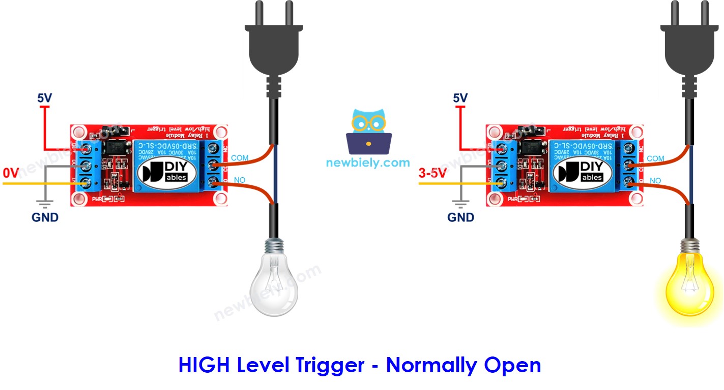
HIGH Level Trigger - Normally Open Mode
To use this mode, connect the high-voltage device to both the COM pin and the NO pin:
- When the IN pin is connected to LOW (0V), the switch remains open, and the device stays OFF.
- When the IN pin is connected to HIGH (5V), the switch closes, and the device turns ON.
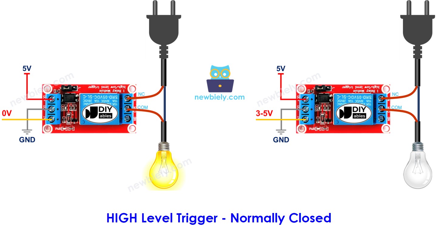
HIGH Level Trigger - Normally Closed Mode
To use this mode, connect the high-voltage device to the COM pin and the NC pin:
- When the IN pin is connected to LOW (0V), the switch is closed, and the device is turned ON.
- When the IN pin is connected to HIGH (5V), the switch is open, and the device is turned OFF.
Summary
The table below shows the relationship between input settings and output states.
| Input modes | Output modes | IN pin (programmable) | Output pins | Relay state | Device state |
|---|---|---|---|---|---|
| HIGH Trigger | Normally Open | LOW | COM and NO pin | ⇒ open | ⇒ OFF |
| HIGH Trigger | Normally Open | HIGH | COM and NO pin | ⇒ closed | ⇒ ON |
| HIGH Trigger | Normally Closed | LOW | COM and NC pin | ⇒ closed | ⇒ ON |
| HIGH Trigger | Normally Closed | HIGH | COM and NC pin | ⇒ open | ⇒ OFF |
| LOW Trigger | Normally Open | LOW | COM and NO pin | ⇒ closed | ⇒ ON |
| LOW Trigger | Normally Open | HIGH | COM and NO pin | ⇒ open | ⇒ OFF |
| LOW Trigger | Normally Closed | LOW | COM and NC pin | ⇒ open | ⇒ OFF |
| LOW Trigger | Normally Closed | HIGH | COM and NC pin | ⇒ closed | ⇒ ON |