Arduino MicroPython LCD 20x4
This tutorial will instruct you how to use a 20x4 LCD I2C display with an Arduino board using MicroPython. You will learn:
- How to connect a 20x4 LCD I2C display to an Arduino
- How to write MicroPython code to display text, integers, floating-point numbers, and custom characters on a 20x4 LCD I2C display
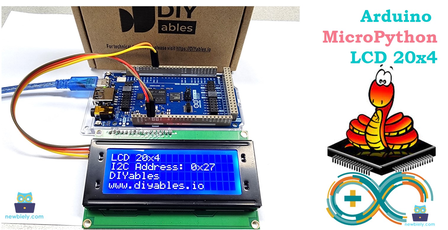
Hardware Preparation
Or you can buy the following kits:
| 1 | × | DIYables Sensor Kit (30 sensors/displays) | |
| 1 | × | DIYables Sensor Kit (18 sensors/displays) |
Disclosure: Some of the links provided in this section are Amazon affiliate links. We may receive a commission for any purchases made through these links at no additional cost to you.
Additionally, some of these links are for products from our own brand, DIYables .
Additionally, some of these links are for products from our own brand, DIYables .
Overview of LCD I2C 20x4
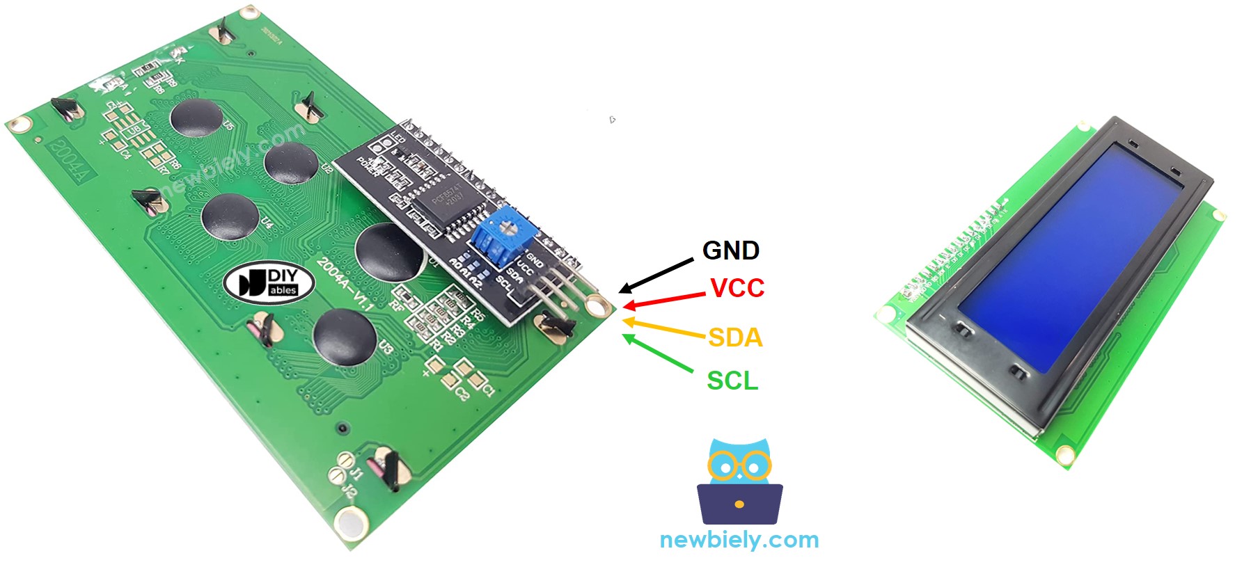
Pinout
The LCD 20x4 I2C connects using the I2C interface and has 4 pins.
- GND pin: Connect this to GND (0 volts).
- VCC pin: Connect this to VCC (5 volts) to power the LCD.
- SDA pin: Used for I2C data signal.
- SCL pin: Used for I2C clock signal.
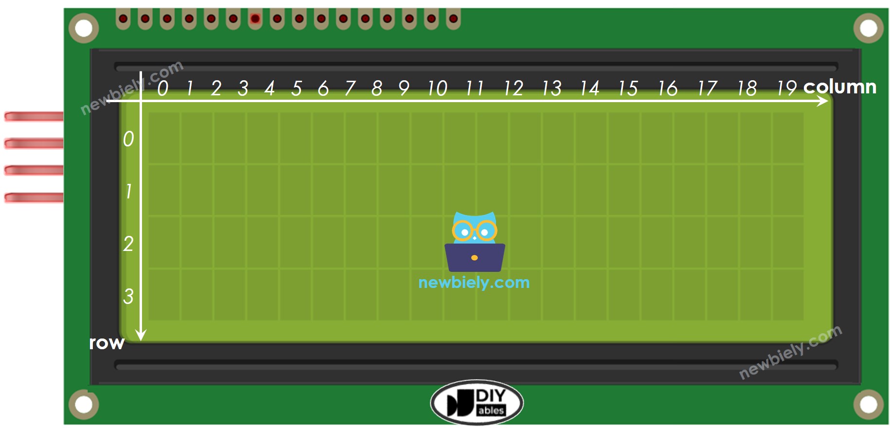
LCD Coordinate
The LCD I2C 20x4 includes 20 columns and 4 rows. Both columns and rows begin at 0.
Wiring Diagram
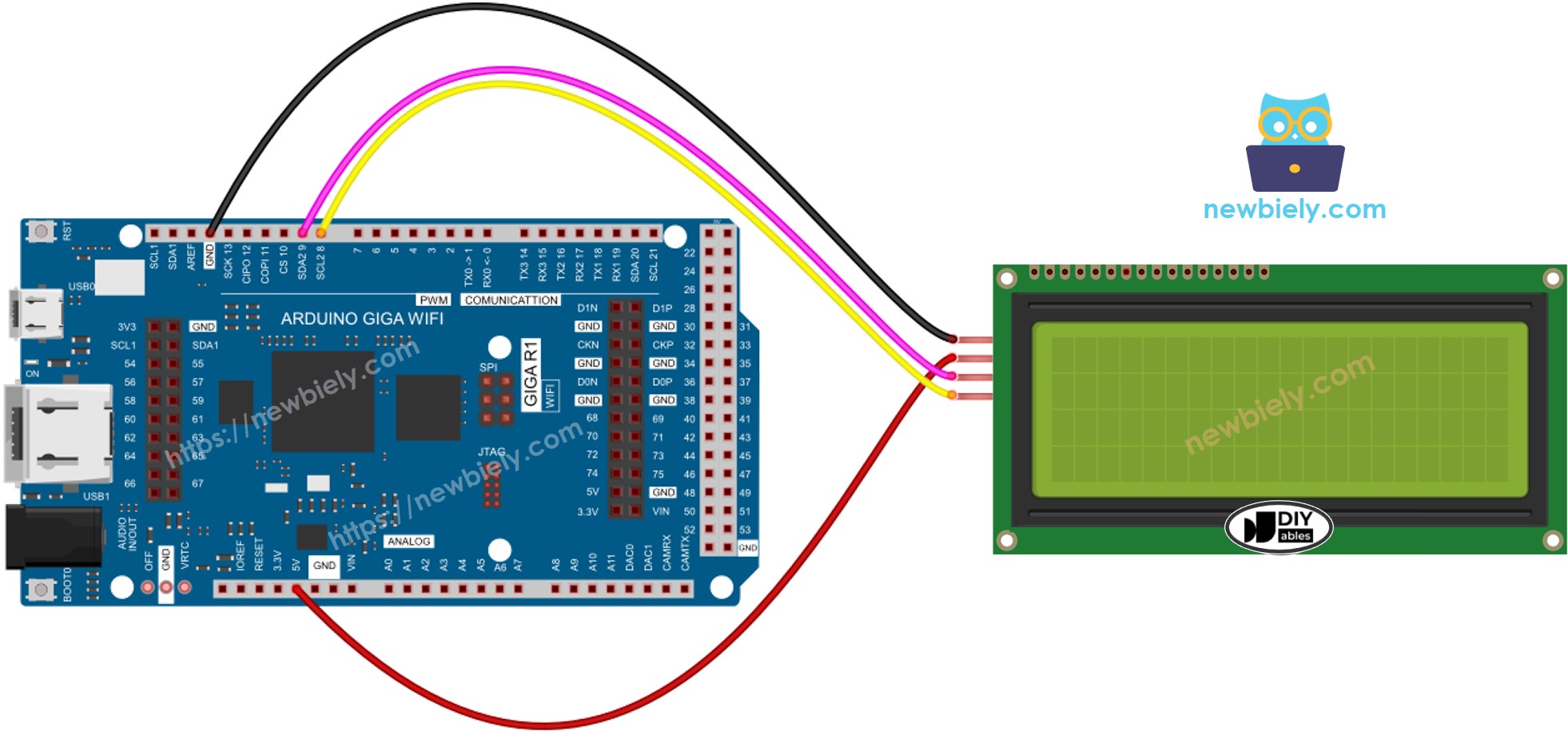
This image is created using Fritzing. Click to enlarge image
| LCD I2C | Arduino Giga |
|---|---|
| VCC | Vin 5V |
| GND | GND |
| SDA | D9 |
| SCL | D8 |
Arduino MicroPython Code
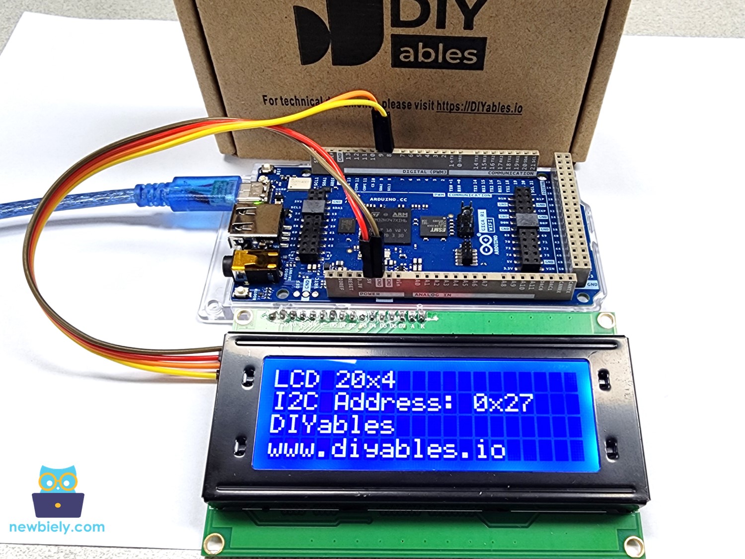
The below MicroPython code displays string, integer and float number on LCD 20x4 display.
"""
This Arduino MicroPython script was developed by newbiely.com
This Arduino MicroPython script is made available for public use without any restriction
For comprehensive instructions and wiring diagrams, please visit:
https://newbiely.com/tutorials/arduino-micropython/arduino-micropython-lcd-20x4
"""
from machine import I2C, Pin
from DIYables_MicroPython_LCD_I2C import LCD_I2C
import utime
# The I2C address of your LCD (Update if different)
I2C_ADDR = 0x27 # Use the address found using the I2C scanner
# Define the number of rows and columns on your LCD
LCD_COLS = 20
LCD_ROWS = 4
# Initialize I2C
i2c = I2C(1) # Arduino Giga R1 WiFi I2C1 pins: SCL-D8, SDA-D9
# Initialize LCD
lcd = LCD_I2C(i2c, I2C_ADDR, LCD_ROWS, LCD_COLS)
# Setup function
lcd.backlight_on()
lcd.clear()
# Main loop function
while True:
lcd.clear()
lcd.set_cursor(0, 0); # Move cursor at the first row, first column
lcd.print("LCD 20x4"); # Display text at the first row
lcd.set_cursor(0, 1); # Move cursor at the second row, first column
lcd.print("I2C Address: 0x27"); # Display text at the second row
lcd.set_cursor(0, 2); # Move cursor at the third row, first column
lcd.print("DIYables"); # Display text at the third row
lcd.set_cursor(0, 3); # Move cursor at the fourth row, first column
lcd.print("www.diyables.io"); # Display text at the fourth row
utime.sleep(2)
lcd.clear()
lcd.set_cursor(0, 0) # Move to the beginning of the first row
lcd.print("Int: ")
lcd.print(str(197)) # Print integer
lcd.set_cursor(0, 1) # Move to the beginning of the second row
lcd.print("Float: ")
lcd.print(str(26.39)) # Print float
utime.sleep(2)
Detailed Instructions
Here’s instructions on how to run the above MicroPython code on Arduino with Thonny IDE:
- Make sure Thonny IDE is installed on your computer.
- Make sure MicroPython firmware is installed on your Arduino board.
- If you are new to Arduino with MicroPython, see the Getting Started with Arduino and MicroPython.
- Connect the LCD 20x4 display to the Arduino according to the provided diagram.
- Connect the Arduino board to your computer with a USB cable.
- Open Thonny IDE and go to Tools Options.
- Under the Interpreter tab, select MicroPython (generic) from the dropdown menu.
- Select the COM port corresponding to your Arduino board (e.g., COM33 on Windows or /dev/ttyACM0 on Linux).
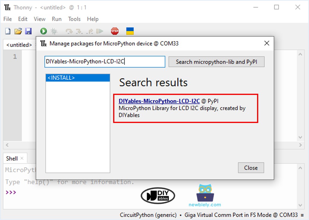
- Navigate to the Tools Manage packages on the Thonny IDE.
- Search “DIYables-MicroPython-LCD-I2C”, then find the LCD I2C library created by DIYables.
- Click on DIYables-MicroPython-LCD-I2C, then click Install button to install LCD I2C library.
- Copy the above provided code and paste it to the Thonny IDE's editor.
- Save the script to your Arduino board by:
- Click the Save button, or use Ctrl+S keys.
- In the save dialog, you will see two sections: This computer and MicroPython device. Select MicroPython device
- Save the file as main.py
- Click the green Run button (or press F5) to run the script. The script will execute.
- Check out the result on the LCD 20x4 display.
Arduino - 20x4 LCD - Custom Character
It is similar to LCD 16x2, you can refer to the custom character section on Arduino MicroPython LCD I2C tutorial, and then adapt it for LCD 20x4 display
