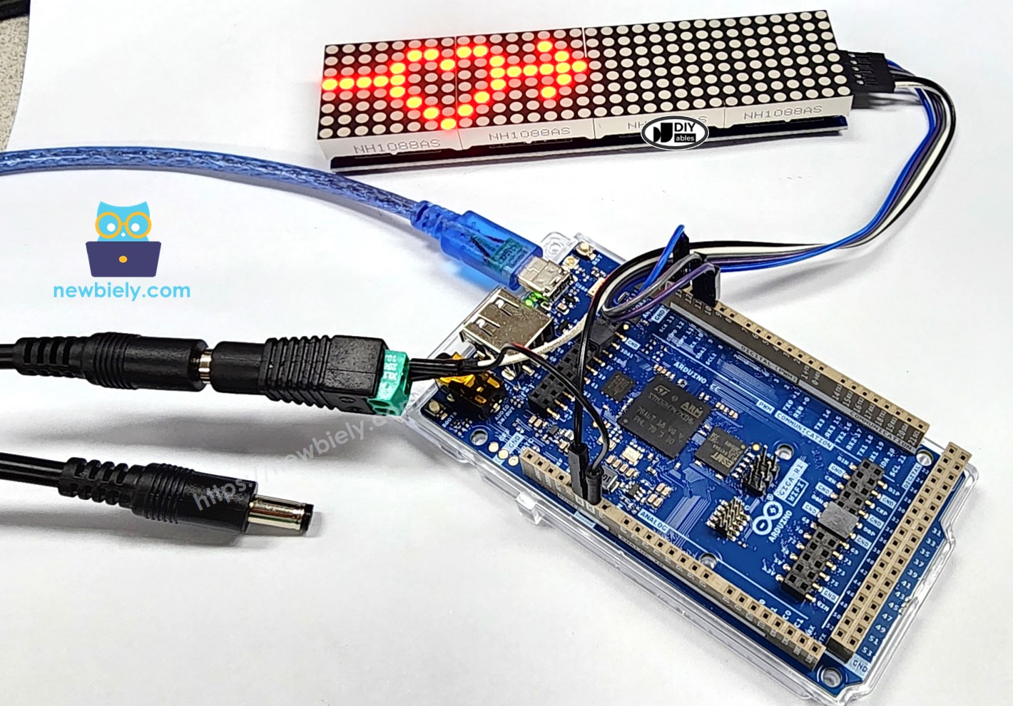
Arduino MicroPython LED Matrix
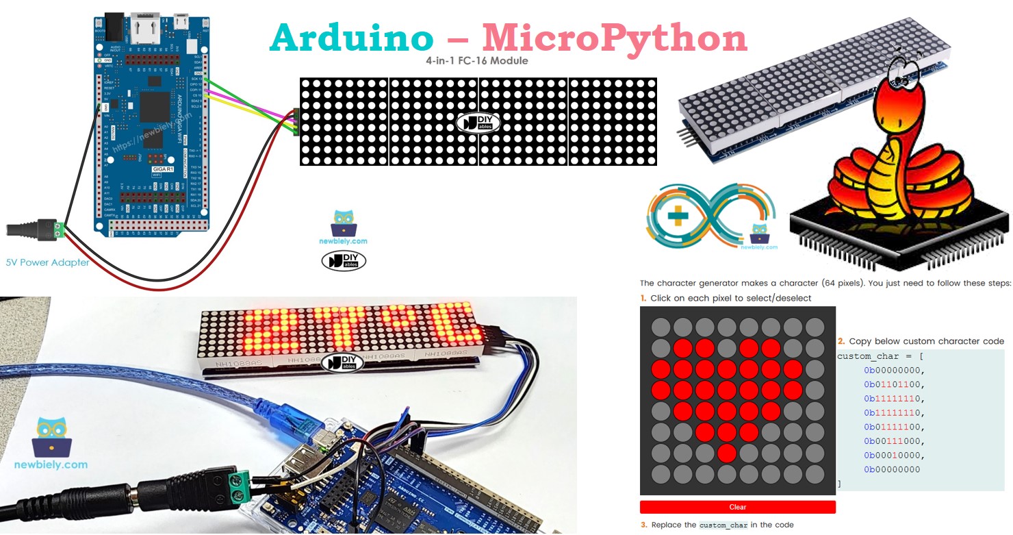
This tutorial teaches you how to use Arduino with LED matrix display modules using MicroPython programming. Specifically, you will learn:
- How to connect the Arduino Giga R1 WiFi to an 8x8 LED Matrix
- How to connect the Arduino Giga R1 WiFi to a 32x8 LED Matrix
- How to write MicroPython code for Arduino to display text and numbers on the LED Matrix
- How to write MicroPython code for Arduino to scroll text on the LED Matrix
- How to write MicroPython code for Arduino to display custom characters on the LED Matrix
You can easily modify the code to work with other LED matrices, such as the 16x8 or 64x8 LED matrix.
Hardware Preparation
Or you can buy the following kits:
| 1 | × | DIYables Sensor Kit (30 sensors/displays) | |
| 1 | × | DIYables Sensor Kit (18 sensors/displays) |
Additionally, some of these links are for products from our own brand, DIYables .
Overview of LED Matrix
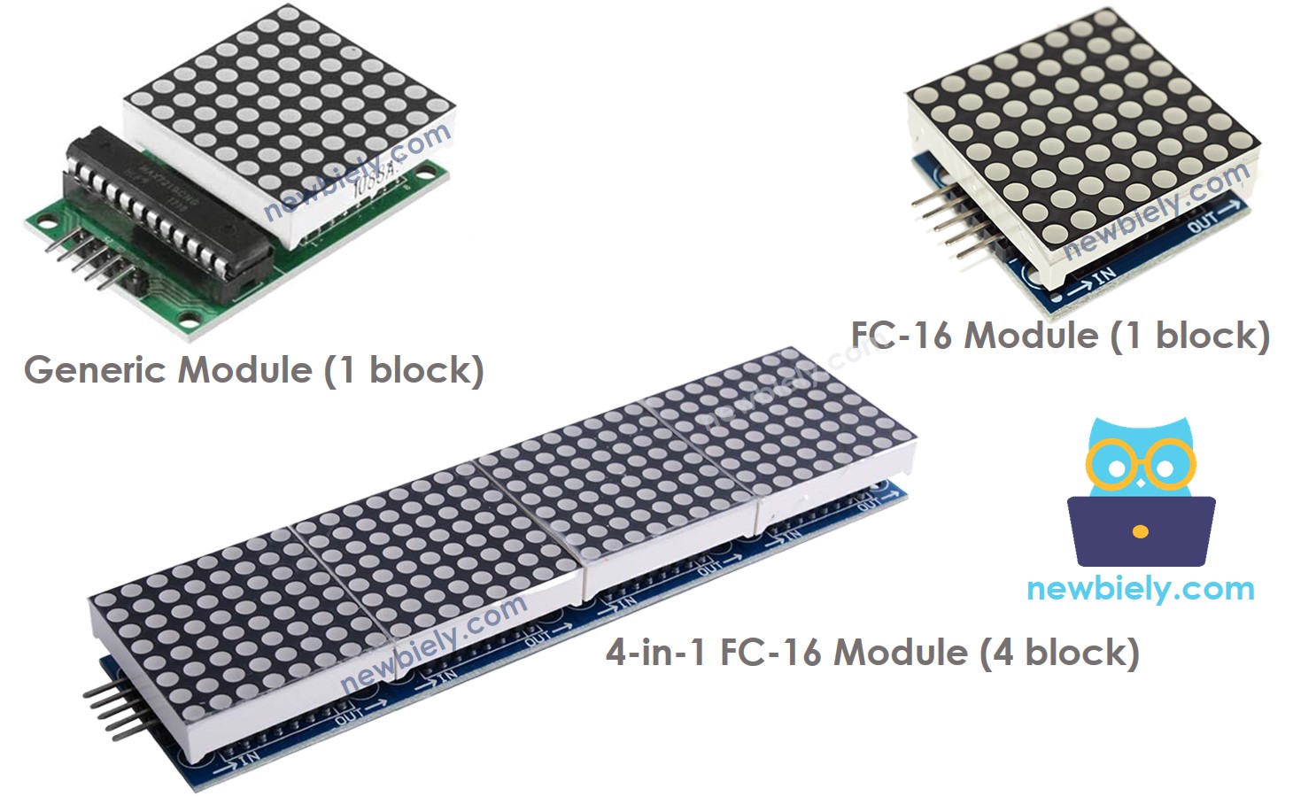
There are different types of LED matrices, but the MAX7219-based LED matrix is commonly used with Arduino. The MAX7219-based LED matrix offers the following features:
- The basic unit of the LED matrix is a block.
- Each block contains an 8x8 LED matrix (64 LEDs) and a MAX7219 driver.
- LED matrices can be created using a single block or by chaining multiple blocks together.
- Pre-assembled LED matrices with multiple blocks are available, such as 4-in-1 or 8-in-1 configurations.
- Alternatively, you can purchase individual blocks and connect them to form a matrix of your desired size. You can also chain 1-in-1, 4-in-1, or 8-in-1 LED matrices together.
- The size of the LED matrix must be specified in your Arduino code.
Pinout
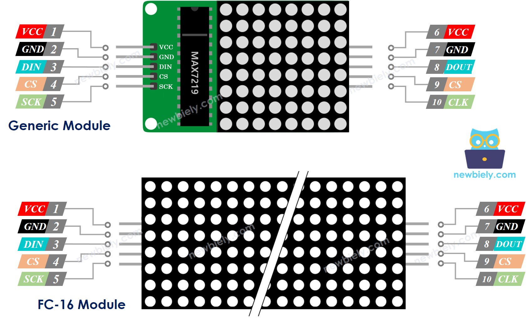
A LED Matrix consists of one or more sections. Each section has two types of connectors:
- Group of Input Pins:
- VCC: Connect to the 5V.
- GMD: Connect to the GND.
- DIN: This is the Data pin. Connect to the SPI MOSI pin on the Arduino.
- CS: Chip Select. Connect to any digital pin on the Arduino.
- CLK: Clock pin. Connect to the SPI CLK pin on the Arduino.
- Group of Output Pins:
- VCC: Connect this to VCC on the next module.
- GND: Connect this to GMD on the next module.
- DOUT: Data Out. Connect to the DIN pin on the next module.
- CS: Connect this to CS on the next module.
- CLK: Connect this to CLK on the next module.
Wiring Diagram
Since the display uses a lot of power (up to 1A at full brightness), avoid using the 5V pin on the Arduino for power. Instead, use an external 5V power supply, and the Arduino and LED matrix can share power from the same 5V adapter.
- How to connect Arduino and led matrix using breadboard
If the LED matrix has only one block:
- Attach the groups of input pins to the Arduino.
- Do not connect the groups of output pins.
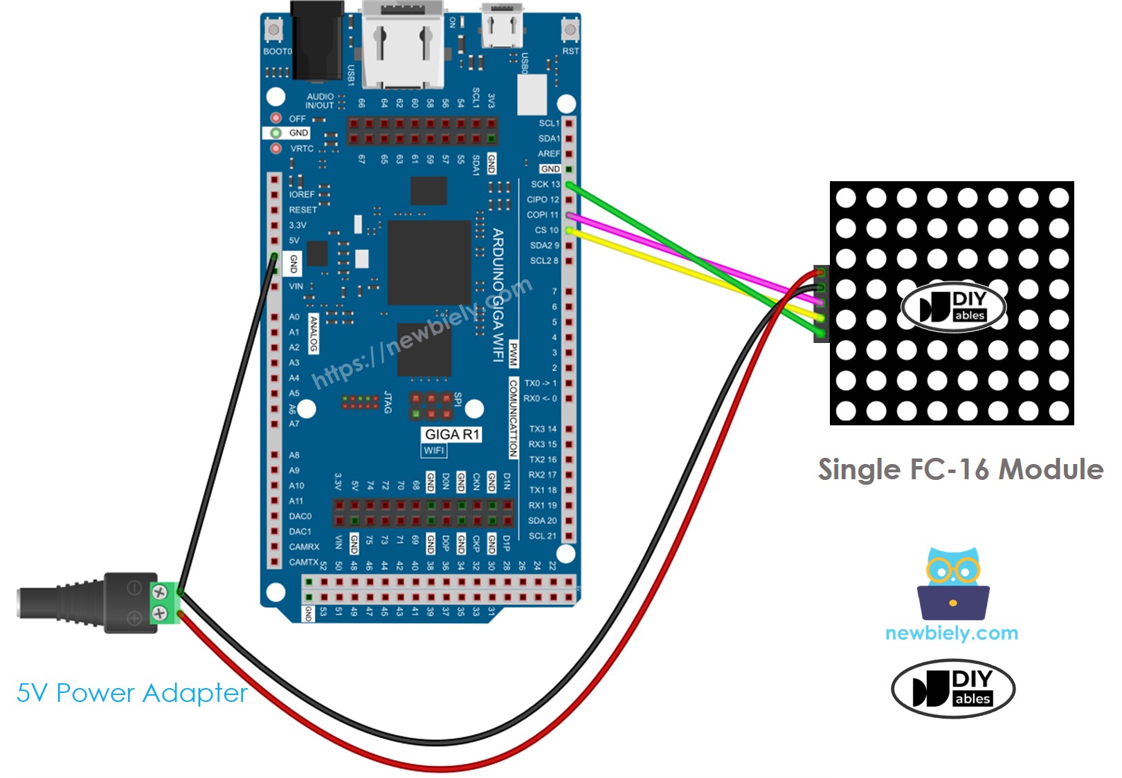
This image is created using Fritzing. Click to enlarge image
If the LED matrix is already put together into several sections:
- Connect the input pins group to the Arduino.
- Do not connect the output pins group.
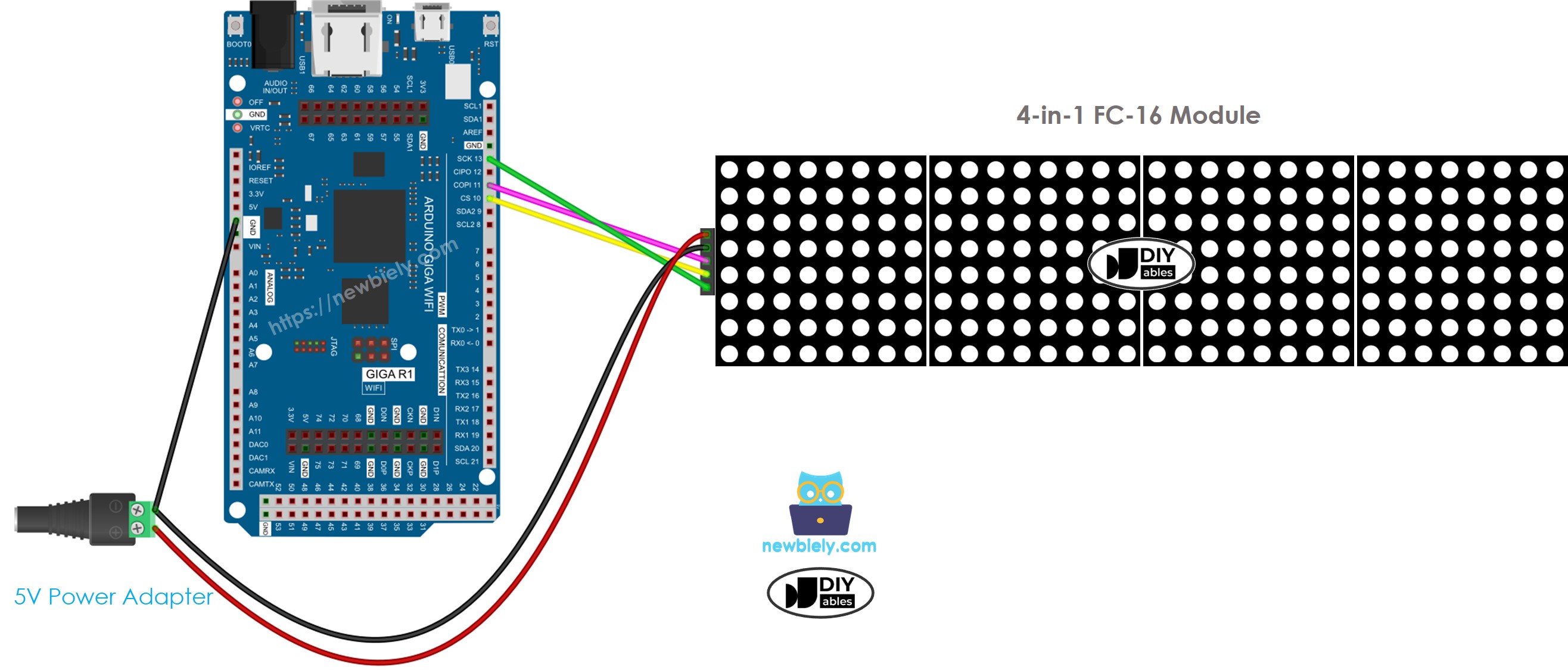
This image is created using Fritzing. Click to enlarge image
If you put together the LED matrix using different components:
- Connect the first block's input pins to the Arduino.
- Connect each block's output pins to the next block's input pins.
- Do not connect the last block's output pins.
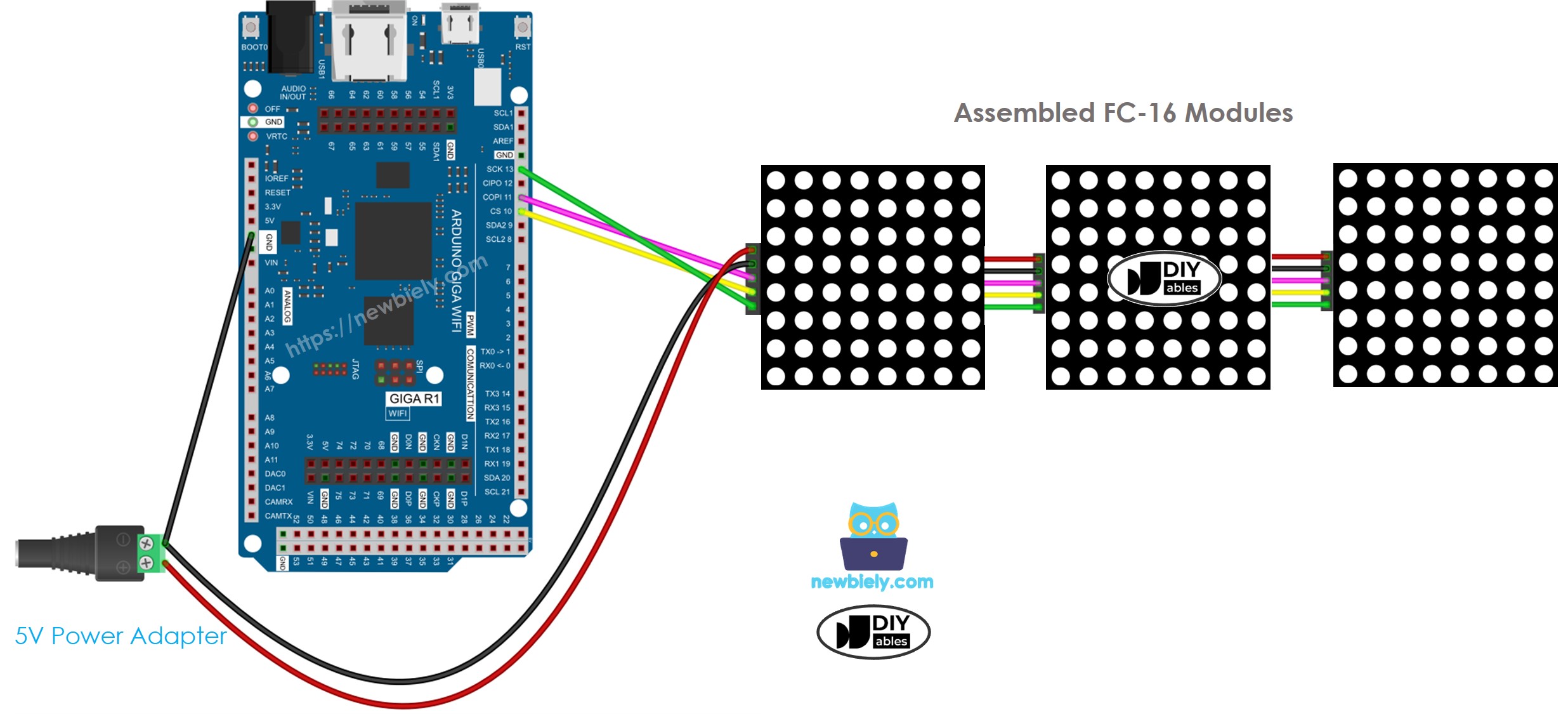
This image is created using Fritzing. Click to enlarge image
Arduino - LED Matrix Code
The below Arduino MicroPython code is written for a 32x8 FC-16 LED matrix display consisting of four blocks. However, it can be easily modified to accommodate different sizes like 8x8, 16x8, 64x8, and others.
Detailed Instructions
Please follow these instructions step by step:
- Ensure that Thonny IDE is installed on your computer.
- Ensure that MicroPython firmware is installed on your Arduino board by.
- If this is your first time using a Arduino with MicroPython, refer to the Arduino MicroPython Getting Started tutorial for detailed instructions.
- Connect the Arduino board to the LED matrix according to the provided diagram.
- Connect the Arduino board to your computer with a USB cable.
- Open Thonny IDE and go to Tools Options.
- Under the Interpreter tab, select MicroPython (generic) from the dropdown menu.
- Select the COM port corresponding to your Arduino board (e.g., COM33 on Windows or /dev/ttyACM0 on Linux).
- Navigate to the Tools Manage packages on the Thonny IDE.
- Search “DIYables-MicroPython-LED-Matrix”, then find the LED Matrix library created by DIYables.
- Click on DIYables-MicroPython-LED-Matrix, then click Install button to install LED Matrix library.
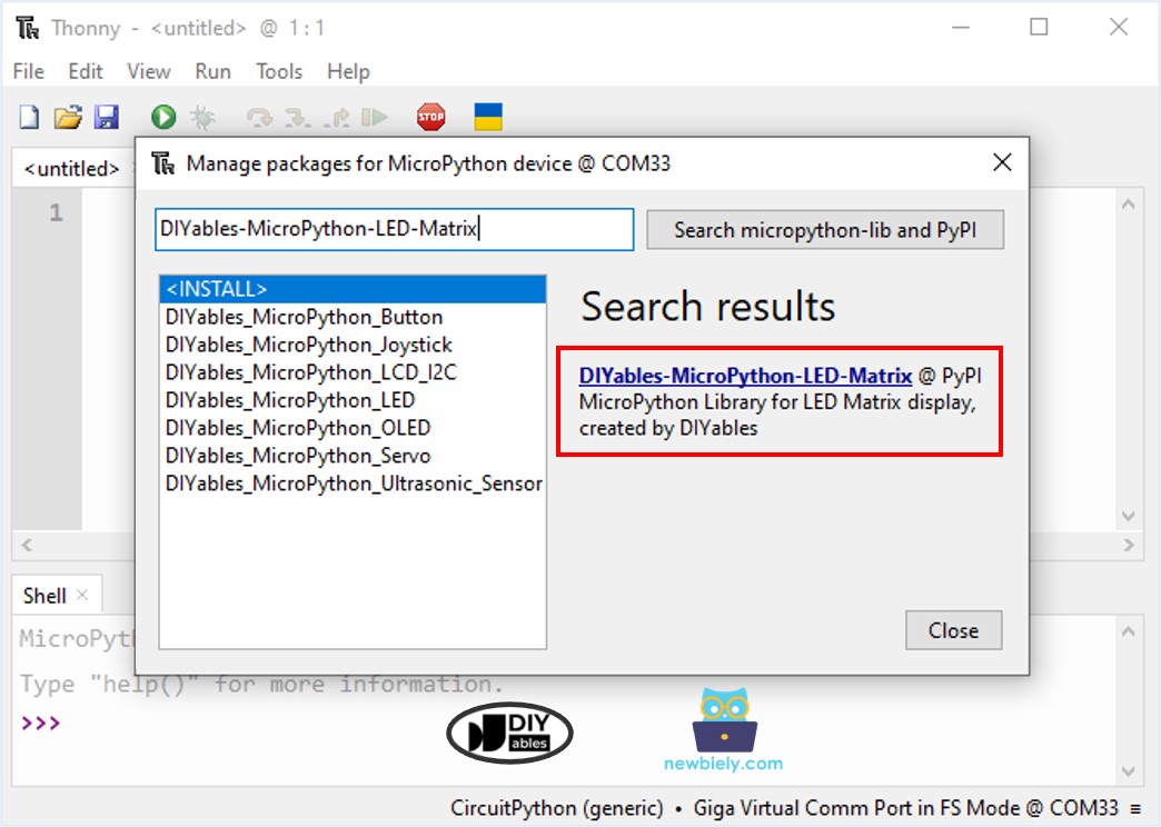
- Copy the above code and paste it to the Thonny IDE's editor.
- Save the script to your Arduino board by:
- Click the Save button, or use Ctrl+S keys.
- In the save dialog, you will see two sections: This computer and MicroPython device. Select MicroPython device
- Save the file as main.py
- Click the green Run button (or press F5) to run the script. The script will execute.
- Check out the LED matrix. It looks like the below:
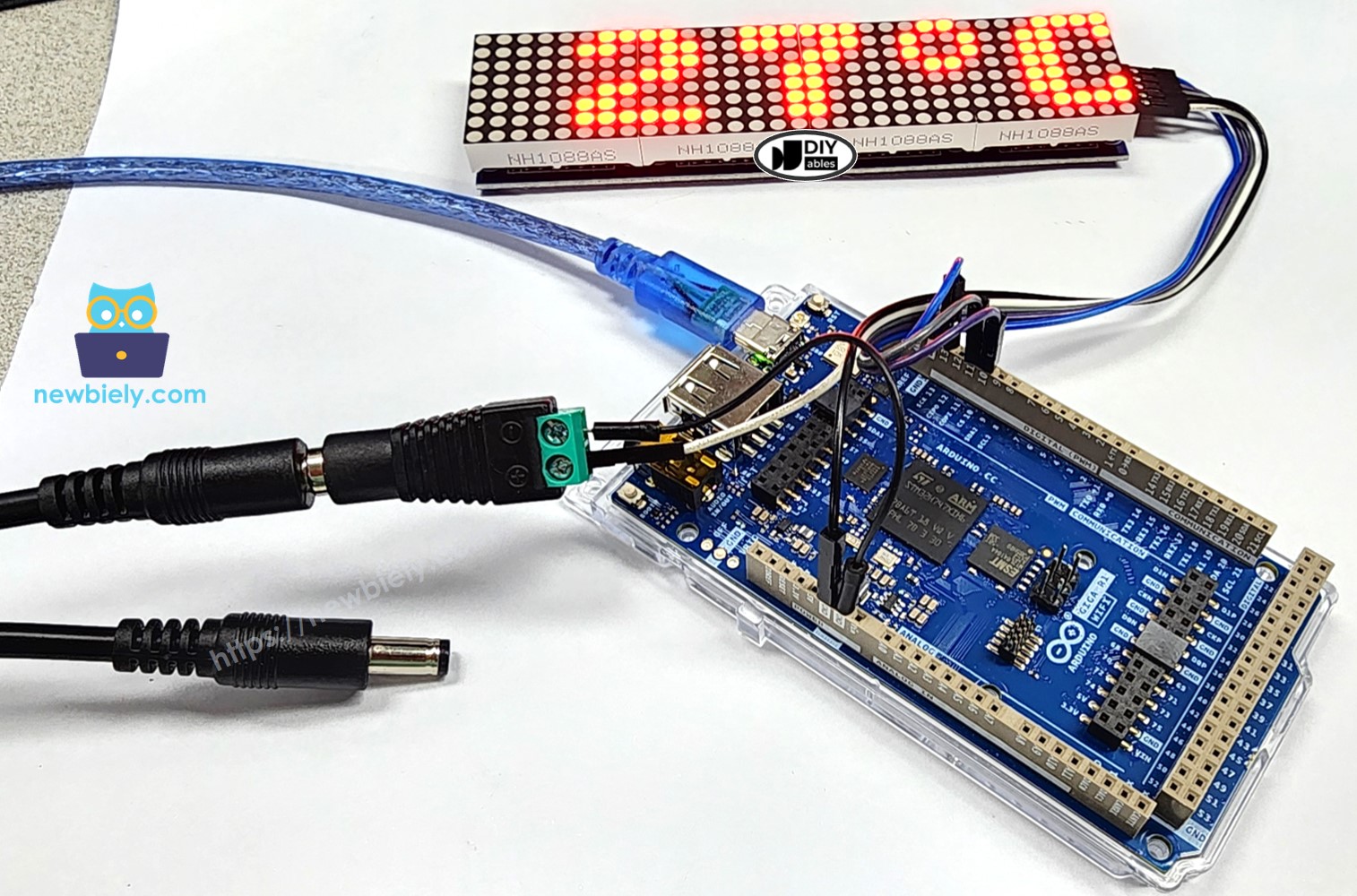
The actual display lighting looks much better than it appears in the image. The camera is unable to accurately capture the true colors of the lighting.
Arduino MicroPython LED Matrix Code – Scrolling Text
When your message is too long for the LED matrix display, you can scroll it across the screen. The MicroPython code below for Arduino demonstrates how to scroll a message on the LED matrix display.
Detailed Instructions
- Copy the provided Arduino MicroPython code and paste it into Thonny's editor.
- Save the MicroPython code to your Arduino board.
- Click the green Run button (or press F5) to execute the code.
- Check out the LED matrix. The scrolling effect looks like the below:
Arduino MicroPython LED Matrix - Custom Character
To display special characters or symbols such as a heart or an angry bird on an LED Matrix display, you need to use the character generator.
The character generator makes a character (64 pixels). You just need to follow these steps:
The Arduino MicroPython code below displays three custom characters on the 32x8 LED matrix:
Detailed Instructions
- Copy the provided Arduino MicroPython code and paste it into Thonny's editor.
- Save the MicroPython code to your Arduino board.
- Click the green Run button (or press F5) to execute the code.
- Check out the LED matrix. It looks like the below:
