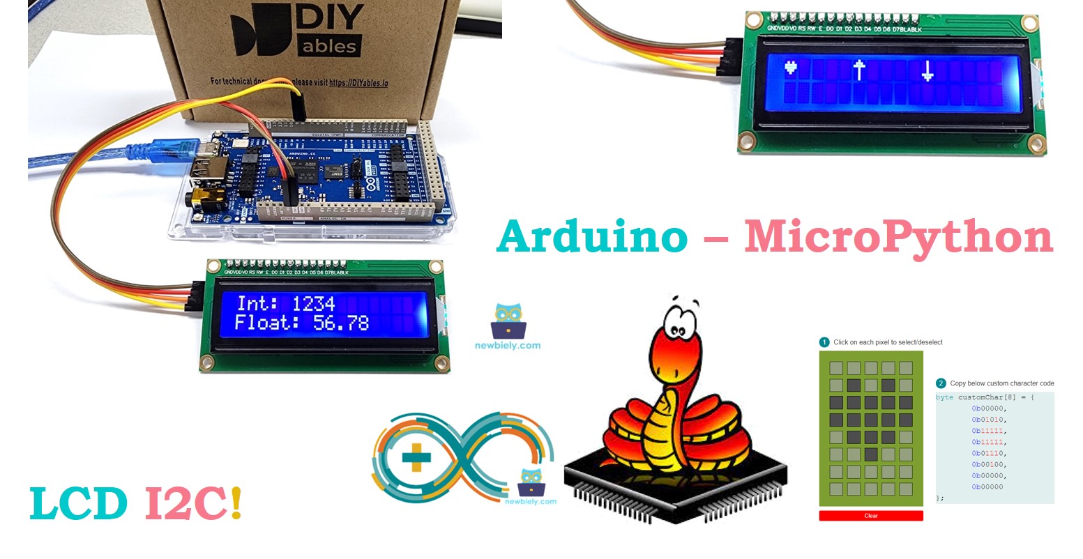
Arduino MicroPython LCD I2C
This guide shows you how to use an Arduino with a 16x2 LCD I2C using MicroPython. You will learn:
- How to connect an LCD I2C to an Arduino
- How to write MicroPython code for Arduino to display text on the LCD I2C
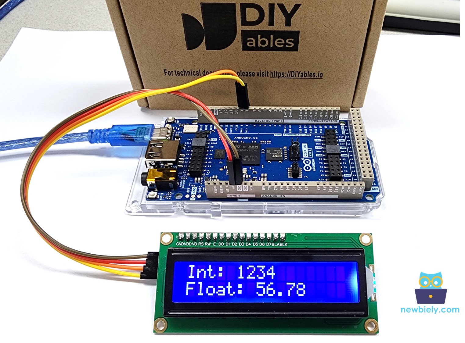
- How to write MicroPython code for Arduino to display numbers on the LCD I2C
- How to write MicroPython code for Arduino to display custom characters on the LCD I2C
Hardware Preparation
Or you can buy the following kits:
| 1 | × | DIYables Sensor Kit (18 sensors/displays) |
Additionally, some of these links are for products from our own brand, DIYables .
Buy Note: Alternatively, you can assemble the LCD I2C display using LCD 1602 Display and PCF8574 I2C Adapter Module.
Overview of LCD I2C 16x2
The 16x2 LCD I2C is a screen with 16 columns and 2 rows. It has an I2C interface and comes with a potentiometer to adjust the screen's contrast.
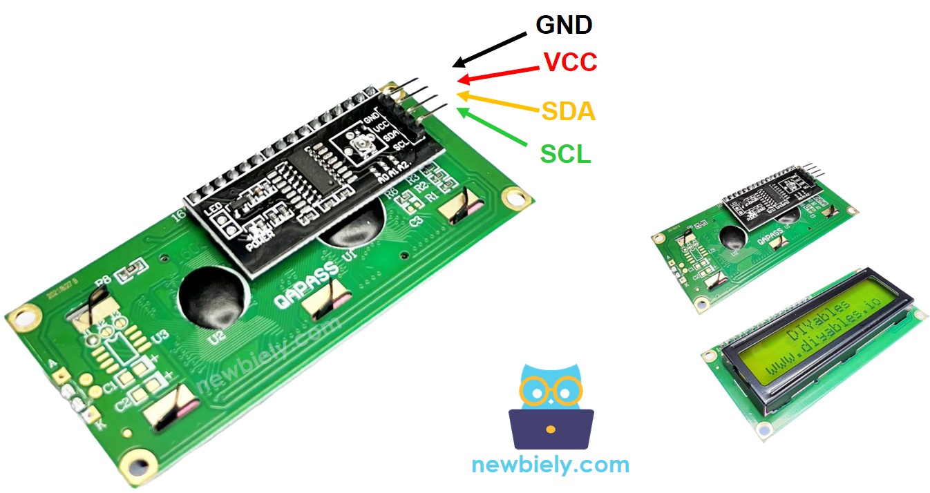
Pinout
The LCD I2C uses an I2C interface and includes 4 pins.
- GND pin: connect to GND (0 volts).
- VCC pin: connect to VCC for power (5 volts).
- SDA pin: transfers I2C data signal.
- SCL pin: transfers I2C clock signal.
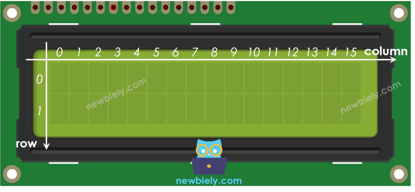
LCD Coordinate
The LCD I2C 16x2 includes 16 columns and 2 rows. The numbering of both columns and rows begins from 0.
Wiring Diagram
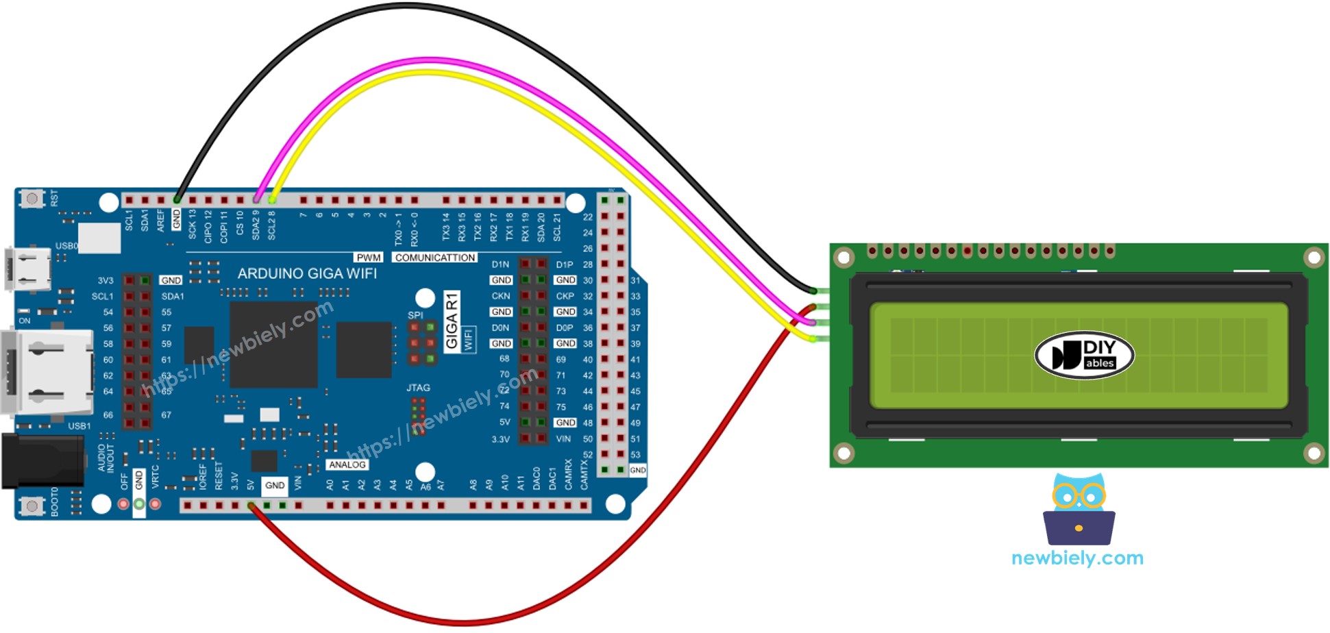
This image is created using Fritzing. Click to enlarge image
| LCD I2C | Arduino Giga |
|---|---|
| VCC | Vin 5V |
| GND | GND |
| SDA | D9 |
| SCL | D8 |
Arduino MicroPython Code
Detailed Instructions
Here’s instructions on how to run the above MicroPython code on Arduino with Thonny IDE:
- Make sure Thonny IDE is installed on your computer.
- Make sure MicroPython firmware is installed on your Arduino board.
- If you are new to Arduino with MicroPython, see the Getting Started with Arduino and MicroPython.
- Connect the LCD I2C display to the Arduino according to the provided diagram.
- Connect the Arduino board to your computer with a USB cable.
- Open Thonny IDE and go to Tools Options.
- Under the Interpreter tab, select MicroPython (generic) from the dropdown menu.
- Select the COM port corresponding to your Arduino board (e.g., COM33 on Windows or /dev/ttyACM0 on Linux).
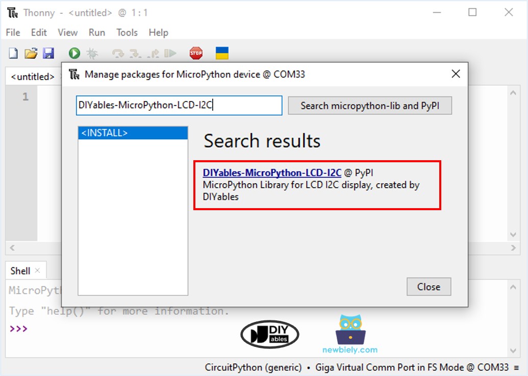
- Navigate to the Tools Manage packages on the Thonny IDE.
- Search “DIYables-MicroPython-LCD-I2C”, then find the LCD I2C library created by DIYables.
- Click on DIYables-MicroPython-LCD-I2C, then click Install button to install LCD I2C library.
- Copy the provided Arduino MicroPython code and paste it into Thonny's editor.
- Save the MicroPython code to your Arduino by:
- Clicking the Save button or pressing Ctrl+S.
- In the save dialog, choose MicroPython device and name the file main.py.
- Click the green Run button (or press F5) to execute the code.
- Check out the result on the LCD display.
Do More with LCD
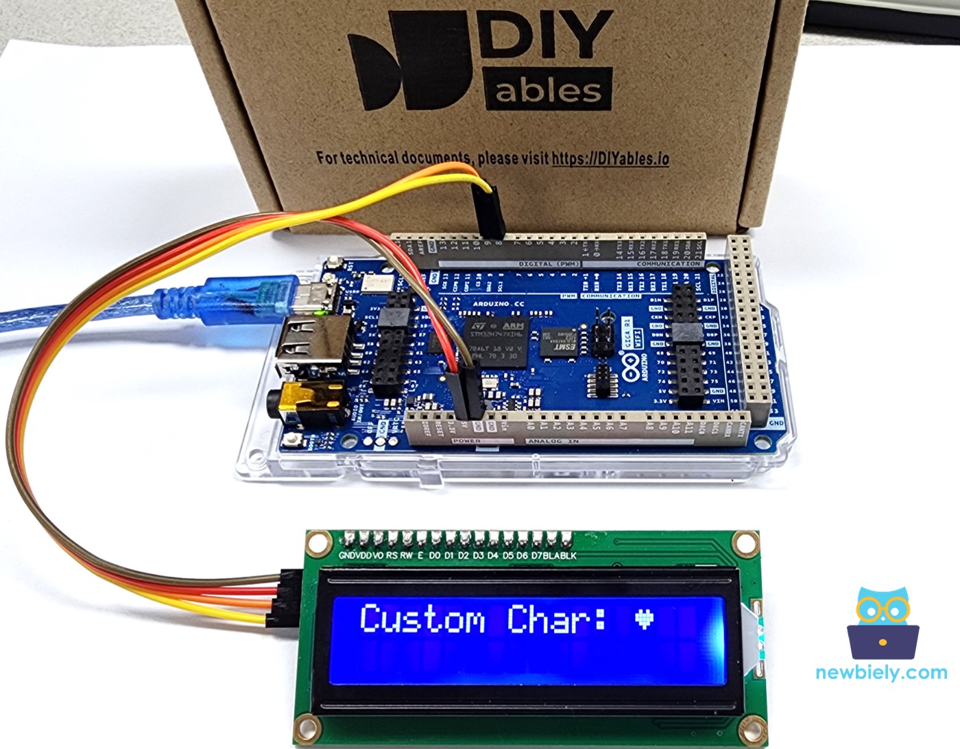
Displaying Custom Character on LCD
To display special characters or symbols (like a heart or an angry bird) on an LCD, you need to use a character generator because the lcd.print() function can only show standard ASCII characters.
The 16x2 LCD can display 32 characters, with 16 positions per line over 2 lines. Each character is made up of 40 pixels, arranged in 8 rows and 5 columns.
The character generator makes a character (40 pixels). You just need to follow these steps:
Result shown on the screen:
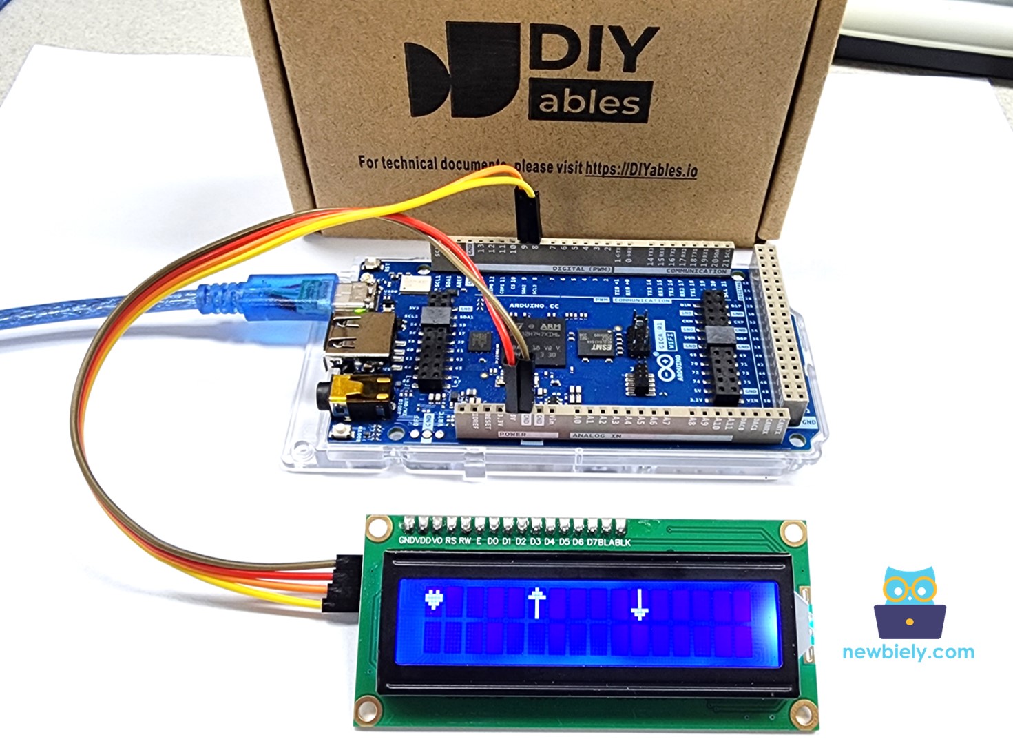
Displaying Multiple custom characters on LCD
We can create up to 8 special characters (from 0 to 7). Here is how to make and show three of these characters.
Result shown on LCD screen:
Summary: How to Use Custom Characters on an LCD
- Create binary code: Use the provided tool to generate the binary code for your custom character.
- Write down the code: Copy the binary code from the tool.
- Create a custom character and position it at a number from 0 to 7
- Show a custom symbol on the LCD display.
Troubleshooting on LCD I2C
If you're having trouble displaying text on your LCD I2C screen, try these steps:
- Adjust the brightness: Turn the potentiometer on the back of the LCD to change the brightness.
- Check the I2C address: The I2C address may differ between manufacturers. Common addresses are 0x27 and 0x3F. Try these addresses to see if they work. If not, run the I2C scanner code on the Arduino to find the correct I2C address.
The result shown in the Shell at the bottom of Thonny: