Raspberry Pi Pico - Actuator
This tutorial instructs you how to use Raspberry Pi Pico to control the linear actuator. In detail, we will discover:
- How a linear actuator works.
- How to make a linear actuator extend or retract.
- How to use an L298N driver and Raspberry Pi Pico to control a linear actuator.
- How to control the speed of a linear actuator.
This guide focuses on linear actuators that do not have feedback. If you need information about linear actuators with feedback, please go to this guide: Raspberry Pi Pico - Actuator with Feedback.
Hardware Preparation
Or you can buy the following kits:
| 1 | × | DIYables Sensor Kit (18 sensors/displays) |
Additionally, some of these links are for products from our own brand, DIYables .
Overview of Linear Actuator

Linear Actuator Pinout
A linear actuator has two wires.
- Positive wire: usually red
- Negative wire: usually black

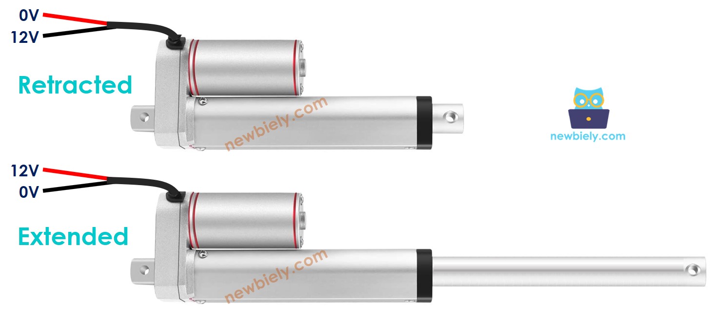
How It Works
When buying a linear actuator, it is important to know its operating voltage. For example, think about a linear actuator that uses 12 volts.
When you link the 12V linear actuator with a 12V power source:
- Attach 12V to the positive wire and GND to the negative wire: this makes the linear actuator extend quickly until it reaches its final point.
- Attach 12V to the negative wire and GND to the positive wire: this makes the linear actuator retract quickly until it reaches its final point.
When you disconnect the power from the actuator by linking the positive and negative wires to the ground, the actuator will stop moving.
※ NOTE THAT:
DC motors, servo motors, and stepper motors without gears cannot hold their position if there is no power and they have a load. But an actuator can hold its position without power, even with a load.
If we use less than 12V for linear actuators, they still function but at a slower speed. This indicates that altering the power supply voltage can vary the speed of the linear actuator. However, accurately adjusting the voltage is challenging, so this approach is not often used. Typically, the voltage remains steady and the speed of the linear actuator is managed with a PWM signal. When the PWM duty cycle increases, the linear actuator moves quicker.
How to control a linear actuator using Raspberry Pi Pico
To operate a linear actuator involves:
- Makes the linear actuator extend as quickly as possible.
- Makes the linear actuator retract as quickly as possible.
- (optional) Changes how fast it extends and retracts.
The Raspberry Pi Pico can create a control signal for a linear actuator. However, this signal has low voltage and current, so it cannot control the actuator directly. We must use a hardware driver between the Raspberry Pi Pico and the linear actuator. The driver has two roles:
- Boost the strength and voltage of the control signal from Raspberry Pi Pico.
- Use an additional signal from Raspberry Pi Pico to switch the polarity of the power supply, which determines the direction.
※ NOTE THAT:
- This guide is suitable for all linear actuators. Here, we show how it works using a 12V linear actuator as an example.
- If you are working with a 5V linear actuator and a Raspberry Pi Pico, remember to add a driver. Both the actuator and the Raspberry Pi Pico operate on 5V, but the Raspberry Pi Pico does not provide sufficient current for the actuator.
This guide is based on the L298N driver. However, there are other options like the L293D chip that can also manage linear actuators.
※ NOTE THAT:
You can use relays as a driver too, but controlling one linear actuator (to extend and retract it) requires four relays.
Overview of L298N Driver
This guide will show you how to use the L298N Driver to control devices such as linear actuators, DC motors, and stepper motors. Here, we'll focus on controlling a linear actuator.
L298N Driver Pinout
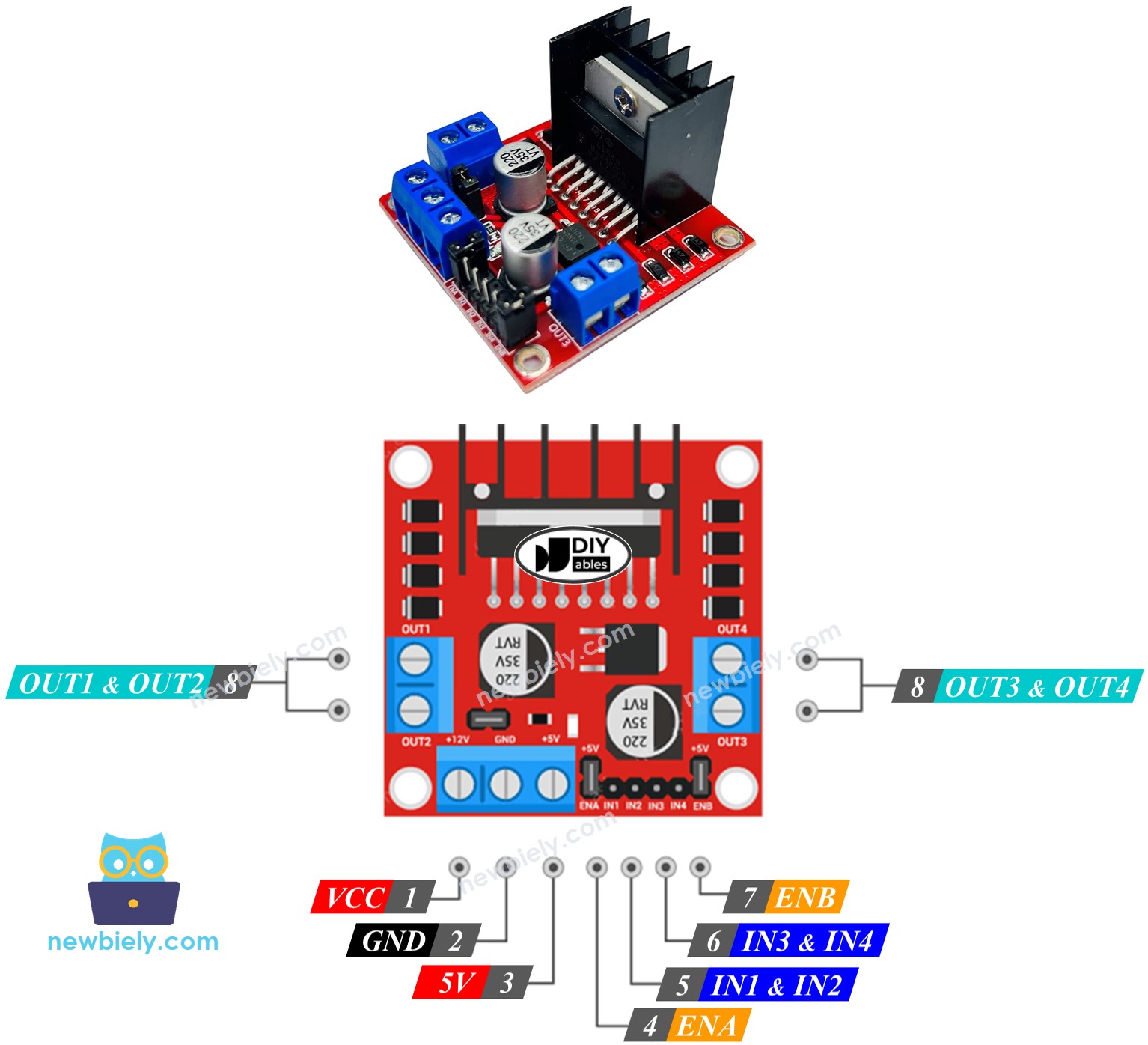
The L298N Driver has two distinct sections, called channel A and channel B. It can control two different linear actuators at the same time because of this design. If linear actuator A is connected to channel A, and linear actuator B is connected to channel B, then the L298N Driver has 13 pins in total.
The common pins for both channels:
- VCC pin: supplies power to the linear actuator. It can handle between 5 and 35 volts.
- GND pin: acts as a common ground and must be connected to GND (0 volts).
- 5V pin: provides power to the L298N module. You can connect it to 5 volts from a Raspberry Pi Pico.
Channel A pins:
- ENA pins: control the speed of linear actuator A. Remove the jumper and connect this pin to a PWM input to change how fast it moves.
- IN1 & IN2 pins: set the movement direction of the linear actuator. When one pin is HIGH and the other is LOW, the actuator will extend or retract. If both are HIGH or both are LOW, the actuator stops.
- OUT1 & OUT2 pins: connect to linear actuator A.
Channel B pins:
- ENB pins: Use these pins to control the speed of linear actuator B. Remove the jumper and apply a PWM signal to change how quickly actuator B moves.
- IN3 & IN4 pins: These pins control the movement direction of a linear actuator. Set one pin HIGH and the other LOW to make the actuator move out or in. If both pins are either HIGH or LOW, the actuator will not move.
- OUT3 & OUT4 pins: Connect these to a linear actuator.
The L298N driver can use two types of input power:
- For the linear actuator (VCC and GND pins): use between 5 and 35V.
- For the inner workings of the L298N module (5V and GND pins): use between 5 and 7V.
The L298N driver includes three jumpers for various uses. For simplicity, please remove all the jumpers from the L298N driver.
We can control two linear actuators at the same time using a Raspberry Pi Pico and an L298N Driver. To run each linear actuator, we only need three pins from the Raspberry Pi Pico.
※ NOTE THAT:
This section of the guide explains how to use channel A to operate a linear actuator. Operating another linear actuator is done similarly.
How To Control Linear Actuator
We will learn how to control a Linear Actuator using the L298N driver.
Wiring Diagram
Before you begin connecting wires, remove all three jumpers from the L298N module.
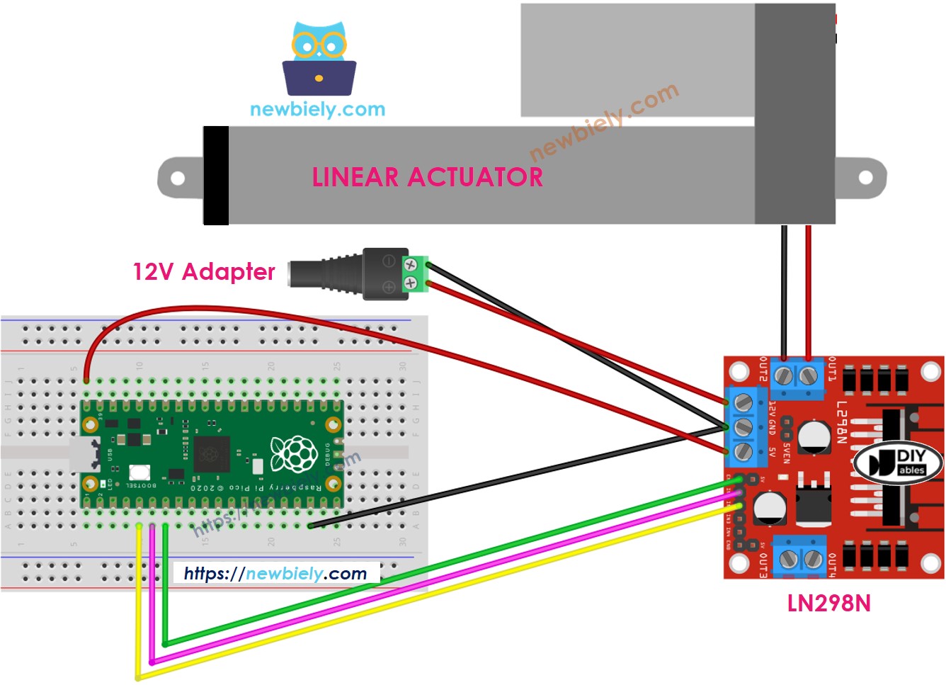
This image is created using Fritzing. Click to enlarge image
How To Make Linear Actuator Expand/Retract
You can change the direction of a Linear Actuator by adjusting the IN1 and IN2 pins to HIGH or LOW. Below is a table that explains how to do this for both channels.
| IN1 pin | IN2 pin | Direction |
|---|---|---|
| LOW | LOW | Linear Actuator A stops |
| HIGH | HIGH | Linear Actuator A stops |
| HIGH | LOW | Linear Actuator A extends |
| LOW | HIGH | Linear Actuator A retracts |
- Extends Linear Actuator A
- The linear actuator A pulls back.
※ NOTE THAT:
If the OUT1 and OUT2 pins are wrongly connected to the linear actuator, it will move in the opposite direction. To correct this, switch the places of the OUT1 and OUT2 pins or alter the control commands for the IN1 and IN2 pins in the software.
How To Stop Linear Actuator from Extending or Retracting
The linear actuator automatically stops moving forward or backward when it reaches its farthest or closest point. We can also set it to stop before it gets to these points.
There are 2 ways to stop a linear actuator.
- Sets IN1 and IN2 pins LOW.
- Sets IN1 and IN2 pins to HIGH.
Raspberry Pi Pico Example Code
This code does the following things:
- Quickly extend the actuator
- Stop the actuator
- Quickly retract the actuator
- Stop the actuator
Detailed Instructions
Please follow these instructions step by step:
- Ensure that Thonny IDE is installed on your computer.
- Ensure that MicroPython firmware is installed on your Raspberry Pi Pico.
- If this is your first time using a Raspberry Pico, refer to the Raspberry Pi Pico - Getting Started tutorial for detailed instructions.
- Remove all three jumpers from the L298N module
- Connect the Raspberry Pi Pico to the linear actuator via L298N module according to the provided diagram.
- Connect the Raspberry Pi Pico to your computer using a USB cable.
- Launch the Thonny IDE on your computer.
- On Thonny IDE, select MicroPython (Raspberry Pi Pico) Interpreter by navigating to Tools Options.
- In the Interpreter tab, select MicroPython (Raspberry Pi Pico) from the drop-down menu.
- Ensure the correct port is selected. Thonny IDE should automatically detect the port, but you may need to select it manually (e.g., COM3 on Windows or /dev/ttyACM0 on Linux).
- Copy the above code and paste it to the Thonny IDE's editor.
- Save the script to your Raspberry Pi Pico by:
- Click the Save button, or use Ctrl+S keys.
- In the save dialog, you will see two sections: This computer and Raspberry Pi Pico. Select Raspberry Pi Pico
- Save the file as main.py
- Click the green Run button (or press F5) to run the script. The script will execute.
- Check out the actuator state. It will:
- The linear actuator extends and stops when it reaches its maximum point.
- The linear actuator maintains its position for some time.
- The linear actuator retracts and stops when it reaches its end point.
- The linear actuator maintains its position for a certain duration.
- This pattern keeps happening again and again.
How To Control the Speed of Linear Actuator via L298N Driver
To change the speed of the linear actuator easily, control it using a PWM signal on the ENA pin instead of just setting it to HIGH. The below MicroPython script shows how to do it: