Raspberry Pi Pico - DC Motor
In this guide, we will show you how to control the DC motor using the Raspberry Pi Pico. We will cover the following details:
- How a DC motor works
- How to control speed and direction of a DC motor using an L298N module
- How to program Raspberry Pi Pico to control speed and direction of a DC motor
Hardware Preparation
Or you can buy the following kits:
| 1 | × | DIYables Sensor Kit (18 sensors/displays) |
Additionally, some of these links are for products from our own brand, DIYables .
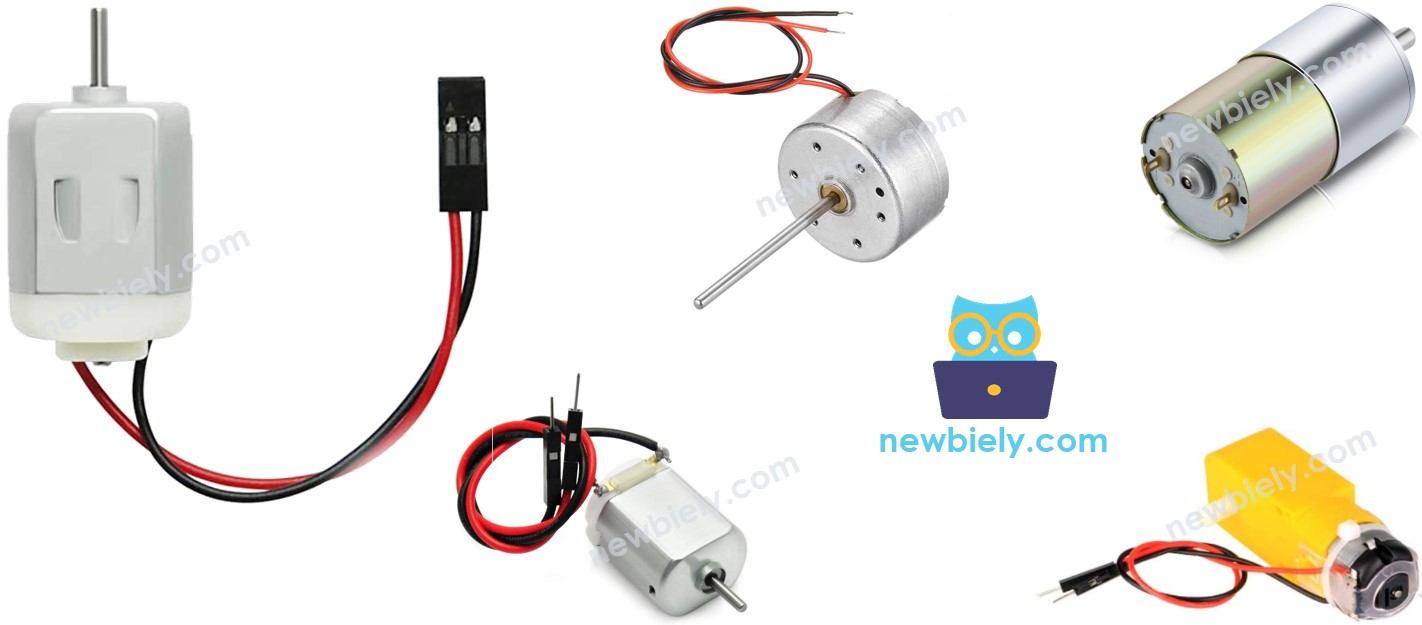
Overview of DC Motor
DC Motor Pinout
A DC motor comes with two wires.
- Positive wire: usually red
- Negative wire: usually black
How It Works
When you buy a DC motor, it is important to know the voltage it needs. For example, if you have a DC motor that requires 12 volts, you should connect it to a 12-volt power source.
- Connect 12V to the positive wire and GND to the negative wire to make the motor rotate clockwise at full speed.
- Connect 12V to the negative wire and GND to the positive wire to make the motor rotate counterclockwise at full speed.
When you swap the connections of two wires on the DC motor as explained before, the way it spins will change. This method controls the spinning direction of the DC motor. Instead of doing this manually, it is done by programming.
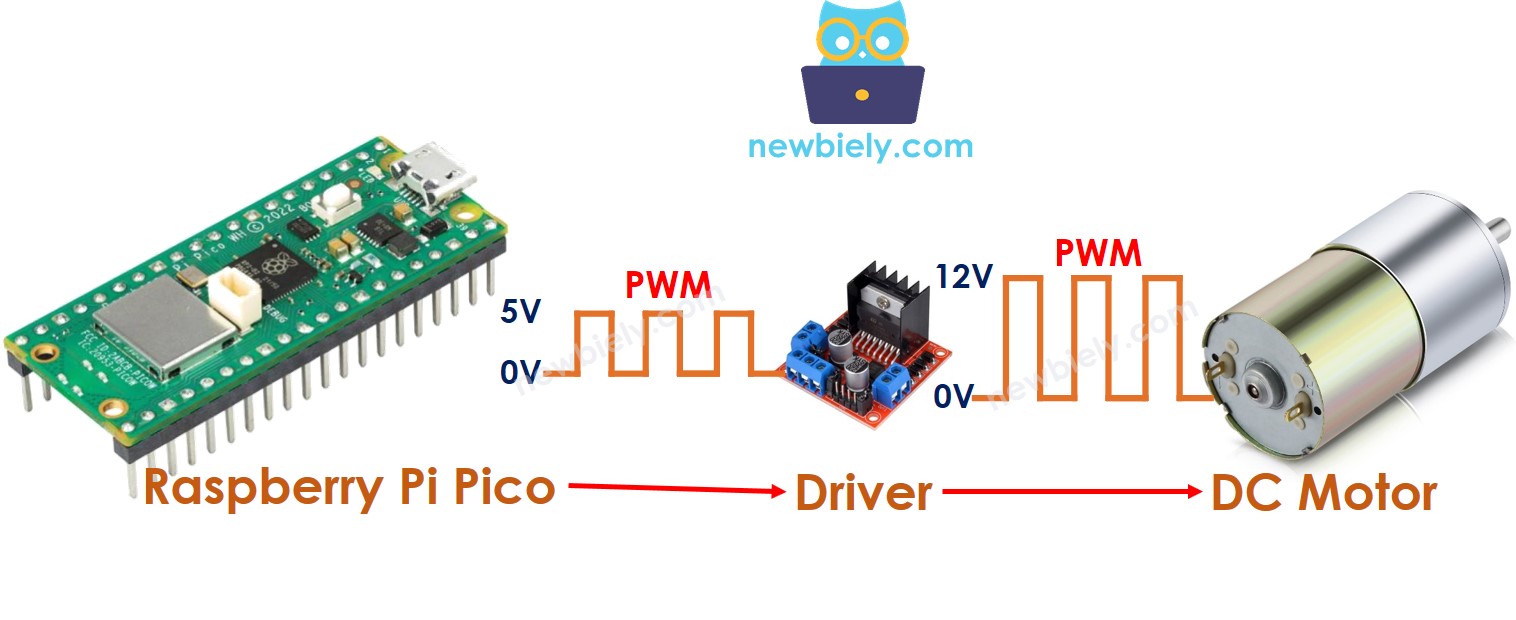
When we provide less than 12V to DC motors, they still operate but not at their maximum speed. This indicates that the motor's speed varies with different voltages. Directly adjusting the voltage can be difficult in practice. Therefore, a more straightforward way to control the speed of a DC motor is used. We maintain a constant voltage from the power supply and manipulate the speed using a PWM (Pulse Width Modulation) signal. The motor spins faster with a higher PWM duty cycle and slower with a lower one.
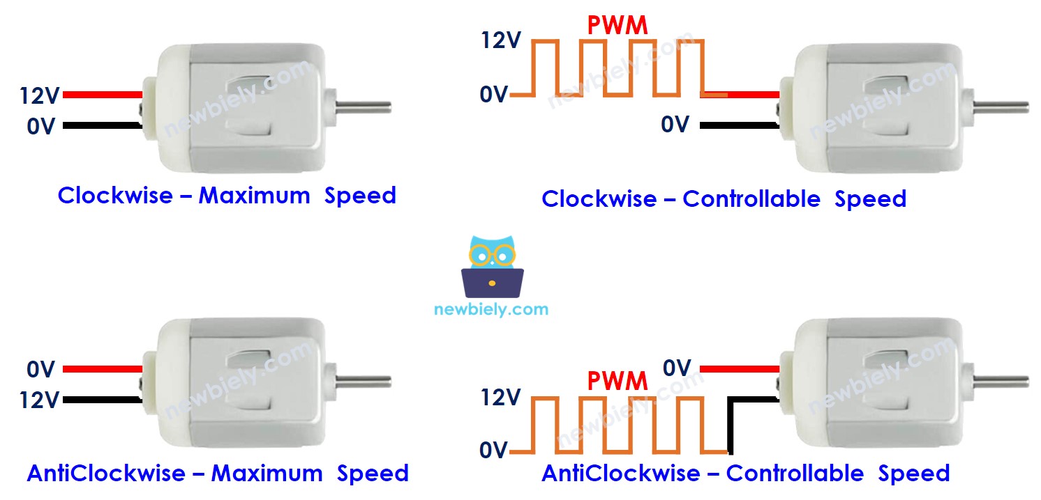
The following animation shows how a PWM signal is used to control the speed of a DC motor:
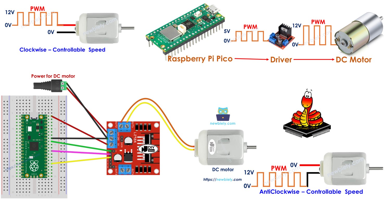
How to control DC motor using Raspberry Pi Pico
To manage a DC motor using a Raspberry Pi Pico, you must handle both its speed and its movement direction. The Raspberry Pi Pico generates a PWM signal which is not strong enough to operate the motor on its own. Consequently, you need a hardware driver that links the Raspberry Pi Pico to the DC motor. This driver has two important functions:
- Boost the power and voltage of the PWM signal from the Raspberry Pi Pico to control speed.
- Get the control signal from the Raspberry Pi Pico to switch the power supply's polarity to control direction.
※ NOTE THAT:
- This guide works for all DC motors. Here, we're using a 12V DC motor to show you how.
- If you use a 5V DC motor, you'll need a driver between the Raspberry Pi Pico and the motor, even though both use 5V. The Raspberry Pi Pico pin can't provide enough current to run the motor by itself.
This guide will show how to use the L298N driver to control DC motors.
Overview of L298N Driver
This guide will show you how to control a DC motor using the L298N Driver.
L298N Driver Pinout
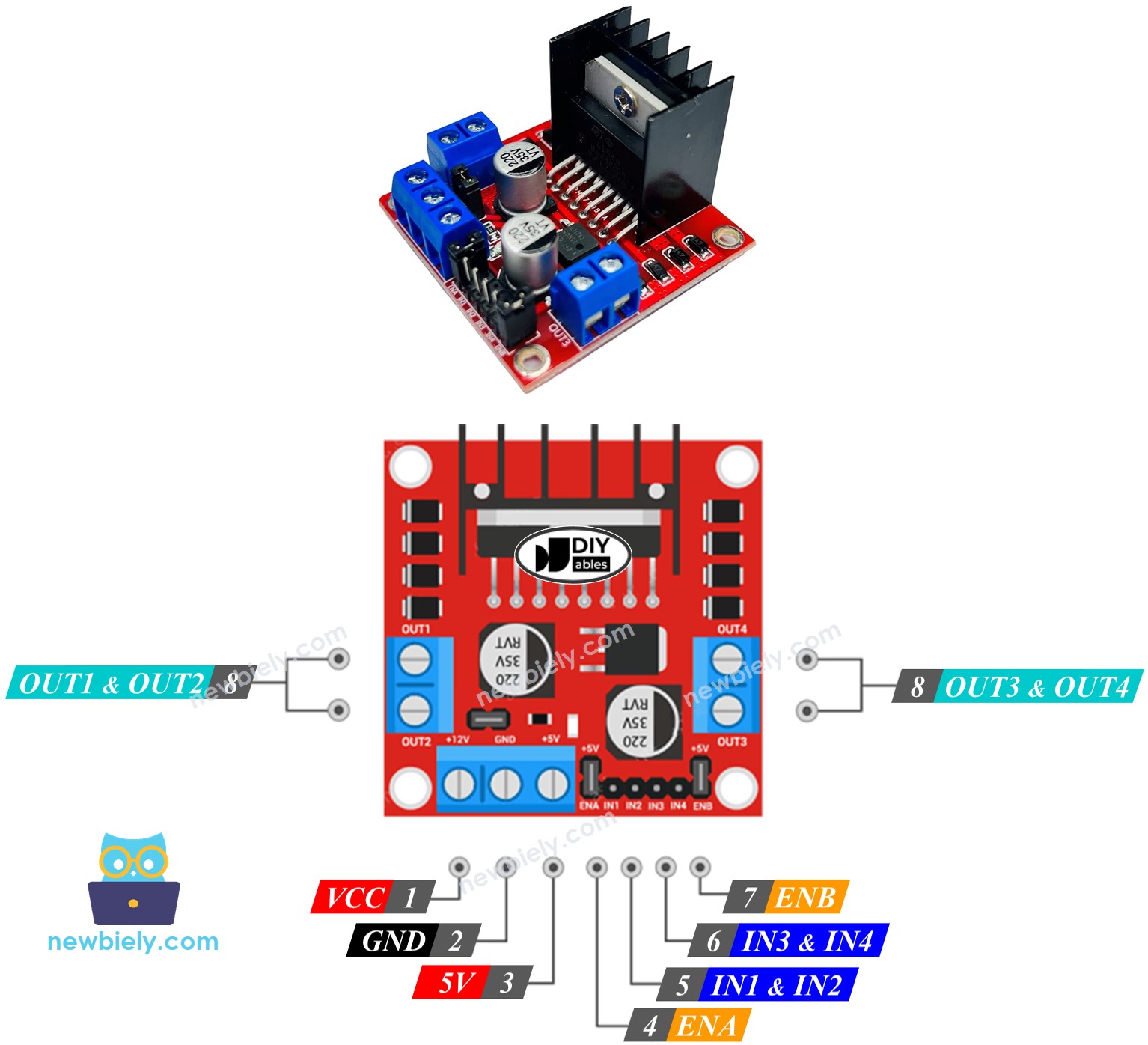
The L298N Driver can control two separate DC motors, called motor A and motor B, at the same time. It has 13 pins.
The common pins for both motors:
- VCC pin: gives power to the motor. The voltage can be from 5 to 35V.
- GND pin: this is a common ground pin and should connect to GND (0V).
- 5V pin: powers the L298N module using 5V from a Raspberry Pi Pico.
Motor A pins (Channel A):
- ENA pins: They manage how fast Motor A moves. To change the speed, take off the jumper and attach the pin to a PWM input.
- IN1 & IN2 pins: They decide which way Motor A rotates. If one pin is HIGH and the other is LOW, Motor A will rotate. If both pins are HIGH or LOW, Motor A will not move.
- OUT1 & OUT2 pins: These are linked to Motor A.
Motor B pins (Channel B):
- ENB pins: These adjust the speed of Motor B. Remove the jumper and connect these pins to a PWM input to control Motor B's speed.
- IN3 & IN4 pins: These determine the spinning direction of Motor B. Motor B spins when IN3 is HIGH and IN4 is LOW, or the other way around. If both are HIGH or both are LOW, Motor B will not spin.
- OUT3 & OUT4 pins: These pins connect to Motor B.
The L298N driver we talked about before uses two kinds of input power:
- One for the DC motor (VCC and GND pins): between 5 and 35V.
- One for the L298N module operation (5V and GGD pins): between 5 and 7V.
The L298N driver includes three jumpers for advanced functions. For simplicity, remove all jumpers from the L298N driver.
You can control two DC motors simultaneously with a Raspberry Pi Pico and an L298N Driver. To manage each motor, you need to connect three pins from the Raspberry Pi Pico.
※ NOTE THAT:
This guide will teach you how to control a DC motor using channel A. You can control another DC motor in a similar method.
Wiring Diagram
Remove all three jumpers from the L298N module before starting the wiring.
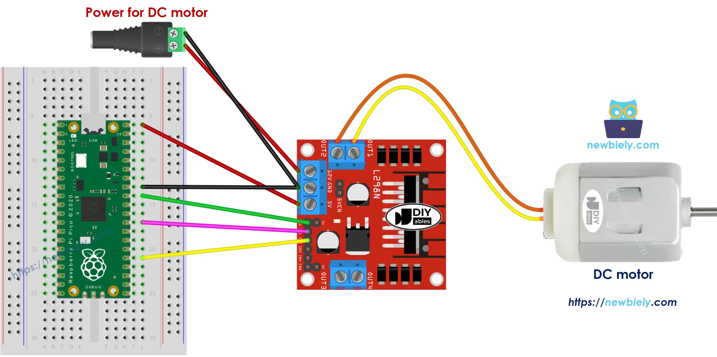
This image is created using Fritzing. Click to enlarge image
How To Control the Speed of DC Motor via L298N Driver
You can change the speed of the DC motor by sending a PWM signal to the ENA pin on the L298N. Here is how you do it:
- Connect a pin from the Raspberry Pi Pico to the ENA pin on the L298N module.
- Use the ena.duty_u16() function to send a PWM signal to the ENA pin. The L298N driver will then amplify this PWM signal to control the DC motor.
The speed can be set between 0 and 255. At 0, the motor will not move. At 255, the motor will move at its fastest speed.
How To Control the Direction of DC Motor via L298N Driver
You can change the rotation direction of a motor by adjusting IN1 and IN2 pins to HIGH or LOW. The table below explains how to control the direction for both channels.
| IN1 pin | IN2 pin | Direction |
|---|---|---|
| LOW | LOW | Motor A stops |
| HIGH | HIGH | Motor A stops |
| HIGH | LOW | Motor A spins Clockwise |
| LOW | HIGH | Motor A spins Anti-Clockwise |
- Motor A turns to the right.
- Motor A rotates in the opposite direction to clockwise.
※ NOTE THAT:
If you reverse the connections of the OUT1 and OUT2 pins with the DC motor pins, the motor will rotate the other way. To correct this, switch the OUT1 and OUT2 pins, or alter the control signals for the IN1 and IN2 pins in the program code.
How To Stop DC Motor Spinning
There are three ways to switch off a DC motor.
- Sets the speed to zero.
- Sets IN1 and IN2 pins to the LOW.
- Sets IN1 and IN2 pins to the HIGH.
How to control a DC motor using L298N driver.
Raspberry Pi Pico Code
The code below performs the following actions:
- Speed up the DC motor
- Change the direction
- Slow down the DC motor
- Stop the motor
Detailed Instructions
Please follow these instructions step by step:
- Ensure that Thonny IDE is installed on your computer.
- Ensure that MicroPython firmware is installed on your Raspberry Pi Pico.
- If this is your first time using a Raspberry Pico, refer to the Raspberry Pi Pico - Getting Started tutorial for detailed instructions.
- Take off all three jumpers from the L298N module.
- Connect the Raspberry Pi Pico to the DC motor via L298N module according to the provided diagram.
- Connect the Raspberry Pi Pico to your computer using a USB cable.
- Launch the Thonny IDE on your computer.
- On Thonny IDE, select MicroPython (Raspberry Pi Pico) Interpreter by navigating to Tools Options.
- In the Interpreter tab, select MicroPython (Raspberry Pi Pico) from the drop-down menu.
- Ensure the correct port is selected. Thonny IDE should automatically detect the port, but you may need to select it manually (e.g., COM3 on Windows or /dev/ttyACM0 on Linux).
- Copy the above code and paste it to the Thonny IDE's editor.
- Save the script to your Raspberry Pi Pico by:
- Click the Save button, or use Ctrl+S keys.
- In the save dialog, you will see two sections: This computer and Raspberry Pi Pico. Select Raspberry Pi Pico
- Save the file as main.py
- Click the green Run button (or press F5) to run the script. The script will execute.
- Observations:
- The DC motor speeds up, then rotates at maximum speed for 1 second.
- The direction of the DC motor changes.
- The DC motor rotates at maximum speed for 1 second in the reverse direction.
- The DC motor slows down.
- The DC motor pauses for 1 second.
- This cycle keeps repeating.
※ NOTE THAT:
In this guide, we will learn how to change the speed of a DC motor compared to its fastest speed. To manage the exact speed in rotations per second, we need to use a PID controller and an encoder. We will discuss how to control the exact speed of the DC motor in another guide.