Raspberry Pi Pico - Actuator with Feedback

In a previous tutorial, we learned about how to use Raspberry Pi Pico with a linear actuator without feedback. In this tutorial, we will learn how to use Raspberry Pi Pico with the linear actuator with feedback. The feedback signal from the actuator tells provides its position during movement, which helps us control where it goes. We will examine the following details:

Hardware Preparation

1×Raspberry Pi Pico W
1×Raspberry Pi Pico (Alternatively)
1×Micro USB Cable
1×12V Linear Actuator with Feedback
1×L298N Motor Driver Module
1×12V Power Adapter
1×DC Power Jack
1×Jumper Wires
1×(Optional) Screw Terminal Expansion Board for Raspberry Pi Pico

Or you can buy the following sensor kits:

1×DIYables Sensor Kit (30 sensors/displays)
1×DIYables Sensor Kit (18 sensors/displays)
Disclosure: Some of the links provided in this section are Amazon affiliate links. We may receive a commission for any purchases made through these links at no additional cost to you.
Additionally, some of these links are for products from our own brand, DIYables.

Overview of Feedback Linear Actuator

A feedback linear actuator is a device that moves in a straight line and includes a system to check and adjust its position. It uses a potentiometer that sends out a voltage signal relating to where the actuator is positioned.

Feedback Linear Actuator Pinout

A feedback linear actuator comes with five wires.

  • Positive Wire: This wire uses a high voltage (12V, 24V, 48V) to control the linear actuator.
  • Negative Wire: This wire uses a high voltage (12V, 24V, 48V) to control the linear actuator.
  • 5V Wire: Connect this wire to the feedback potentiometer at 5V or 3.3V.
  • GND Wire: Connect this wire to the feedback potentiometer at the ground (GND).
  • Potentiometer Wire: Also called the feedback or output wire, this wire changes its voltage value according to the stroke position.
Feedback Linear Actuator Pinout

How It Works

When we apply a high voltage to the positive and negative wires, the actuator will either stretch out or pull back. To explain this, if we connect:

  • Connect 12V (or 24V, 48V) to the positive wire and GND to the negative wire: the actuator will extend at its highest speed until it fully extends.
  • Connect 12V (or 24V, 48V) to the negative wire and GND to the positive wire: the actuator will retract at its highest speed until it fully retracts.
  • If the actuator's power is switched off (by connecting GND to both its wires) while it is extending or retracting, it will stop moving.

※ NOTE THAT:

  • The voltage required to operate the actuator depends on its specific features. Look at the datasheet or manual to determine the correct voltage.
  • The actuator can keep its position without electricity, even when supporting a weight.

The voltage in the potentiometer's wire changes when the actuator moves. By measuring this voltage, we can determine the position of the stroke.

Wiring Diagram

Remove all three jumpers from the L298N module before starting the wiring.

The wiring diagram between Raspberry Pi and Pico Linear Actuator L298N Driver

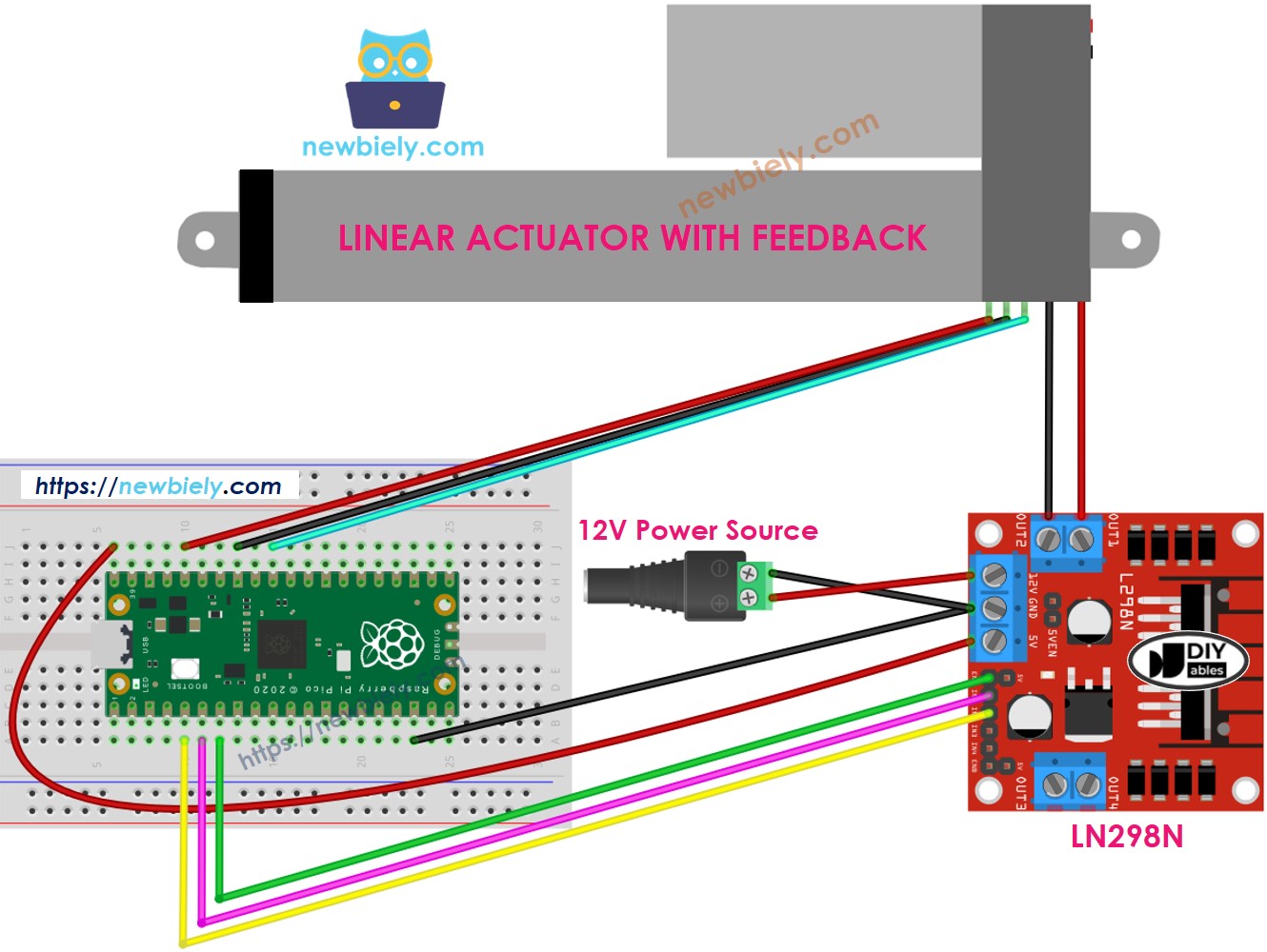
This image is created using Fritzing. Click to enlarge image

How to control extend/retract a linear actuator

Learn about the Raspberry Pi Pico Actuator by clicking here.

How to find the position of the linear actuator

Here's how to locate the stroke position on a linear actuator:

Calibration

  • Use a ruler to find out how long the actuator moves or look at the datasheet for details.
  • To see the values when the linear actuator is fully open or closed, run this code.
""" This Raspberry Pi Pico MicroPython code was developed by newbiely.com This Raspberry Pi Pico code is made available for public use without any restriction For comprehensive instructions and wiring diagrams, please visit: https://newbiely.com/tutorials/raspberry-pico/raspberry-pi-pico-actuator-with-feedback """ from machine import Pin, ADC import time # Define pins ENA_PIN = 5 # The Raspberry Pi Pico pin GP5 connected to the EN1 pin of L298N IN1_PIN = 4 # The Raspberry Pi Pico pin GP4 connected to the IN1 pin of L298N IN2_PIN = 3 # The Raspberry Pi Pico pin GP3 connected to the IN2 pin of L298N POTENTIOMETER_PIN = 26 # The Raspberry Pi Pico pin GP26 (ADC0) connected to the potentiometer of the actuator # Initialize digital pins as outputs ena = Pin(ENA_PIN, Pin.OUT) in1 = Pin(IN1_PIN, Pin.OUT) in2 = Pin(IN2_PIN, Pin.OUT) # Initialize the potentiometer as an ADC pin potentiometer = ADC(Pin(POTENTIOMETER_PIN)) # Set ENA_PIN to HIGH to enable the motor driver ena.value(1) # Main loop to extend and retract the actuator with feedback while True: # Extend the actuator in1.value(1) in2.value(0) time.sleep(20) # Wait for 20 seconds (20000 ms) # Read the potentiometer value after fully extending POTENTIOMETER_MAX = potentiometer.read_u16() print("POTENTIOMETER_MAX =", POTENTIOMETER_MAX) # Retract the actuator in1.value(0) in2.value(1) time.sleep(20) # Wait for 20 seconds (20000 ms) # Read the potentiometer value after fully retracting POTENTIOMETER_MIN = potentiometer.read_u16() print("POTENTIOMETER_MIN =", POTENTIOMETER_MIN)
  • You will see the record in the Shell at the bottom of Thonny like in the example below.
Shell x
>>> %Run -c $EDITOR_CONTENT
MPY: soft reboot POTENTIOMETER_MAX = 987 POTENTIOMETER_MIN = 13
MicroPython (Raspberry Pi Pico) • Board CDC @ COM29 ≡
  • Write these values.
  • If the minimum value is more than the maximum value, exchange IN1_PIN with INI2_PIN.
  • Change three values in the following code.

Raspberry Pi Pico code that calculate the position of the actuator

""" This Raspberry Pi Pico MicroPython code was developed by newbiely.com This Raspberry Pi Pico code is made available for public use without any restriction For comprehensive instructions and wiring diagrams, please visit: https://newbiely.com/tutorials/raspberry-pico/raspberry-pi-pico-actuator-with-feedback """ from machine import Pin, ADC import time # Define pins ENA_PIN = 5 # The Raspberry Pi Pico pin GP5 connected to the EN1 pin of L298N IN1_PIN = 4 # The Raspberry Pi Pico pin GP4 connected to the IN1 pin of L298N IN2_PIN = 3 # The Raspberry Pi Pico pin GP3 connected to the IN2 pin of L298N POTENTIOMETER_PIN = 26 # The Raspberry Pi Pico pin GP26 (ADC0) connected to the potentiometer of the actuator # Define constants STROKE_LENGTH = 102 # Stroke length in millimeters POTENTIOMETER_MAX = 987 # Max potentiometer value POTENTIOMETER_MIN = 13 # Min potentiometer value # Initialize digital pins as outputs ena = Pin(ENA_PIN, Pin.OUT) in1 = Pin(IN1_PIN, Pin.OUT) in2 = Pin(IN2_PIN, Pin.OUT) # Initialize the potentiometer as an ADC pin potentiometer = ADC(Pin(POTENTIOMETER_PIN)) # Set ENA_PIN to HIGH to enable the motor driver ena.value(1) def map_value(x, in_min, in_max, out_min, out_max): # Map a value from one range to another. return int((x - in_min) * (out_max - out_min) / (in_max - in_min) + out_min) # Main loop to extend the actuator and read the stroke position while True: # Extend the actuator in1.value(1) in2.value(0) # Read the potentiometer value potentiometer_value = potentiometer.read_u16() # Map the potentiometer value to stroke position in millimeters stroke_pos = map_value(potentiometer_value, POTENTIOMETER_MIN, POTENTIOMETER_MAX, 0, STROKE_LENGTH) # Print the stroke position print("The stroke's position =", stroke_pos, "mm") time.sleep(1) # Wait for 1 second before the next reading
  • Modify the three altered values in the code
  • Upload the code to the Raspberry Pi Pico
  • Check out the results in the Shell at the bottom of Thonny
Shell x
>>> %Run -c $EDITOR_CONTENT
MPY: soft reboot The stroke's position = 2 mm The stroke's position = 35 mm The stroke's position = 43 mm The stroke's position = 60 mm The stroke's position = 68 mm The stroke's position = 79 mm The stroke's position = 83 mm The stroke's position = 96 mm The stroke's position = 100 mm
MicroPython (Raspberry Pi Pico) • Board CDC @ COM29 ≡

How to control a linear actuator to a specific position

""" This Raspberry Pi Pico MicroPython code was developed by newbiely.com This Raspberry Pi Pico code is made available for public use without any restriction For comprehensive instructions and wiring diagrams, please visit: https://newbiely.com/tutorials/raspberry-pico/raspberry-pi-pico-actuator-with-feedback """ from machine import Pin, ADC import time # Define pins ENA_PIN = 5 # The Raspberry Pi Pico pin GP5 connected to the EN1 pin of L298N IN1_PIN = 4 # The Raspberry Pi Pico pin GP4 connected to the IN1 pin of L298N IN2_PIN = 3 # The Raspberry Pi Pico pin GP3 connected to the IN2 pin of L298N POTENTIOMETER_PIN = 26 # The Raspberry Pi Pico pin GP26 (ADC0) connected to the potentiometer of the actuator # Define constants STROKE_LENGTH = 102 # Stroke length in millimeters POTENTIOMETER_MAX = 987 # Max potentiometer value POTENTIOMETER_MIN = 13 # Min potentiometer value TOLERANCE = 5 # Tolerance in millimeters targetPosition_mm = 50 # Target position in millimeters # Initialize digital pins as outputs ena = Pin(ENA_PIN, Pin.OUT) in1 = Pin(IN1_PIN, Pin.OUT) in2 = Pin(IN2_PIN, Pin.OUT) # Initialize the potentiometer as an ADC pin potentiometer = ADC(Pin(POTENTIOMETER_PIN)) # Set ENA_PIN to HIGH to enable the motor driver ena.value(1) def map_value(x, in_min, in_max, out_min, out_max): # Map a value from one range to another. return int((x - in_min) * (out_max - out_min) / (in_max - in_min) + out_min) def ACTUATOR_extend(): in1.value(1) in2.value(0) def ACTUATOR_retract(): in1.value(0) in2.value(1) def ACTUATOR_stop(): in1.value(0) in2.value(0) # Main loop to control the actuator while True: # Read the potentiometer value potentiometer_value = potentiometer.read_u16() # Map the potentiometer value to stroke position in millimeters stroke_pos = map_value(potentiometer_value, POTENTIOMETER_MIN, POTENTIOMETER_MAX, 0, STROKE_LENGTH) # Print the stroke position print("The stroke's position =", stroke_pos, "mm") # Control the actuator based on the target position and tolerance if stroke_pos < (targetPosition_mm - TOLERANCE): ACTUATOR_extend() elif stroke_pos > (targetPosition_mm + TOLERANCE): ACTUATOR_retract() else: ACTUATOR_stop() time.sleep(0.1) # Small delay to avoid excessive CPU usage

Video Tutorial

※ OUR MESSAGES

  • As freelancers, We are AVAILABLE for HIRE. See how to outsource your project to us
  • Please feel free to share the link of this tutorial. However, Please do not use our content on any other websites. We invested a lot of effort and time to create the content, please respect our work!