ESP32 MicroPython Potentiometer
This tutorial shows you how to use a potentiometer with ESP32 and MicroPython. In detail, We will learn:
- How a potentiometer works.
- How to connnect a potentiometer to a ESP32.
- How to write MicroPython code for the ESP32 to read value from the potentiometer and convert them into practical values.
Hardware Preparation
Or you can buy the following kits:
| 1 | × | DIYables ESP32 Starter Kit (ESP32 included) | |
| 1 | × | DIYables Sensor Kit (18 sensors/displays) |
Additionally, some of these links are for products from our own brand, DIYables .
Overview of Potentiometer
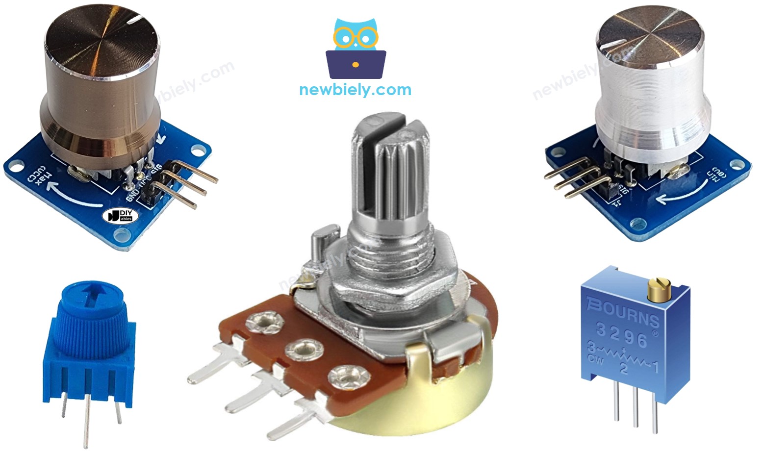
A rotary potentiometer, which is also called a rotary angle sensor, is used to adjust settings manually like stereo volume, lamp brightness, or how much you zoom in on an oscilloscope.
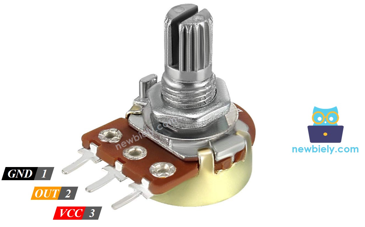
Pinout
A potentiometer usually has three pins.
- GND pin: connect to GND (0 volts)
- VCC pin: connect to VCC (5 volts or 3.3 volts)
- Output pin: sends voltage to ESP32's input pin.
※ NOTE THAT:
You can switch the positions of the GND pin and the VCC pin.
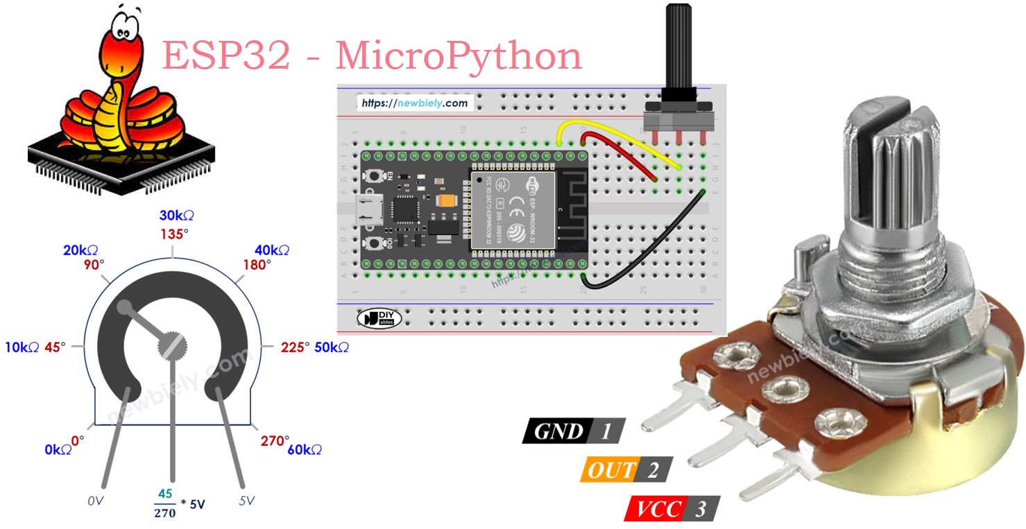
How It Works
The potentiometer's shaft turns from 0 degrees, near the GND, to a maximum position near the VCC pin, called ANGLE_MAX.
The voltage at the output pin ranges from the ground (GND) voltage to the supply voltage (VCC). As you rotate the shaft, the output voltage changes accordingly.
- If the angle is 0 degrees, there is no voltage (0 volts) at the output pin.
- If the angle is ANGLE_MAX, the output pin's voltage is the same as VCC’s voltage.
- For angles between 0 degrees and ANGLE_MAX, the output voltage is calculated as: angle × VCC / ANGLE_MAX.
※ NOTE THAT:
The value of ANGLE_MAX changes depending on the manufacturer. Normally, we do not focus on the value of ANGLE_MAX unless we need to calculate the rotation angle (see the use cases section).
ESP32 - Rotary Potentiometer
The ESP32's ADC pins can function as analog inputs, converting a voltage range from 0 volts to VCC into whole numbers between 0 and 4095. These numbers are referred to as ADC values or analog values.
You can connect the output pin of a potentiometer to one of the ESP32's analog input pins, enabling the ESP32 to read the ADC value and convert it into a usable number.
The number obtained by the ESP32 is not an angle or a direct voltage but rather a whole number between 0 and 4095. This value can then be mapped or converted to a different range as needed for specific applications.
Use Cases
- Changing the ADC value into an angle.
- Changing the ADC value into voltage.
- Changing the ADC value to a value you can control (like the loudness of a stereo, how bright something is, or the speed of a motor). This is often the most common use.
Rescale Range
| FROM | TO | |||
|---|---|---|---|---|
| Angle | rotated by user | 0° | → | ANGLE_MAX |
| Voltage | from potentiometer's pin | 0V | → | 3.3V |
| ADC value | read by ESP32 | 0 | → | 4095 |
| Other value | converted by ESP32 | VALUE_MIN | → | VALUE_MAX |
Wiring Diagram
- How to connect ESP32 and potentiometer using breadboard
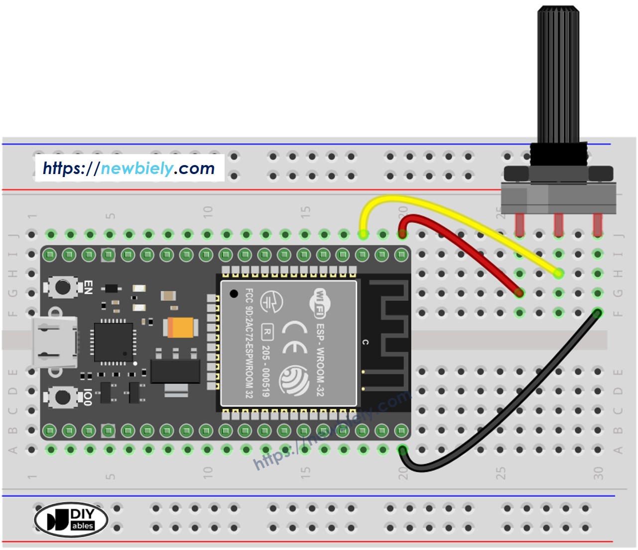
This image is created using Fritzing. Click to enlarge image
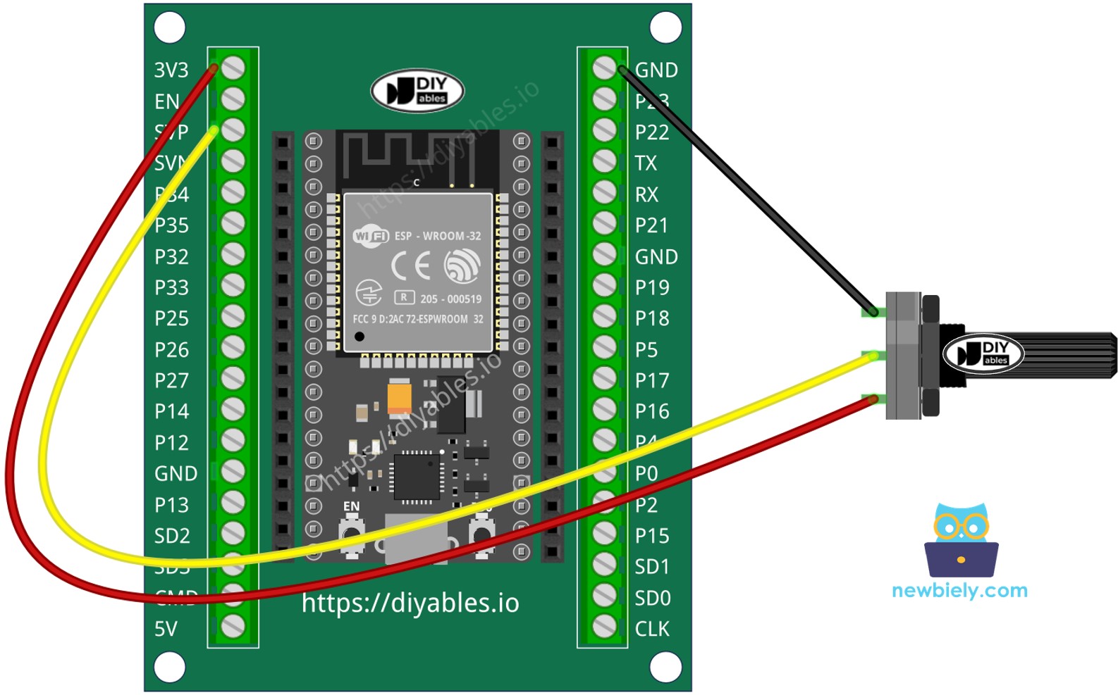
- How to connect ESP32 and potentiometer using screw terminal block breakout board
ESP32 MicroPython Code
Detailed Instructions
Here’s instructions on how to set up and run your MicroPython code on the ESP32 using Thonny IDE:
- Make sure Thonny IDE is installed on your computer.
- Confirm that MicroPython firmware is loaded on your ESP32 board.
- If this is your first time using an ESP32 with MicroPython, check out the ESP32 MicroPython Getting Started guide for step-by-step instructions.
- Connect the ESP32 board to the potentiometer according to the provided diagram.
- Connect the ESP32 board to your computer with a USB cable.
- Open Thonny IDE on your computer.
- In Thonny IDE, go to Tools Options.
- Under the Interpreter tab, choose MicroPython (ESP32) from the dropdown menu.
- Make sure the correct port is selected. Thonny IDE usually detects it automatically, but you might need to select it manually (like COM12 on Windows or /dev/ttyACM0 on Linux).
- Copy the provided MicroPython code and paste it into Thonny's editor.
- Save the code to your ESP32 by:
- Clicking the Save button or pressing Ctrl+S.
- In the save dialog, choose MicroPython device.
- Name the file main.py.
- Click the green Run button (or press F5) to execute the script.
- Adjust the potentiometer
- Check out the message in the Shell at the bottom of Thonny.
※ NOTE THAT:
This tutorial demonstrates how to use the adc.read() function to read values from an ADC (Analog-to-Digital Converter) connected to a potentiometer. The ESP32's ADC is suitable for projects that do not require high precision. However, if your project needs accurate measurements, keep the following in mind:
- The ESP32 ADC is not perfectly accurate and may require calibration for precise results. Each ESP32 board may vary slightly, so calibration is necessary for each individual board.
- Calibration can be challenging, especially for beginners, and might not always yield the exact results you desire.
For projects requiring high precision, consider using an external ADC (e.g., ADS1115) with the ESP32 or opt for an Arduino, which has a more reliable ADC. If you still wish to calibrate the ESP32 ADC, refer to the ESP32 ADC Calibration Driver.