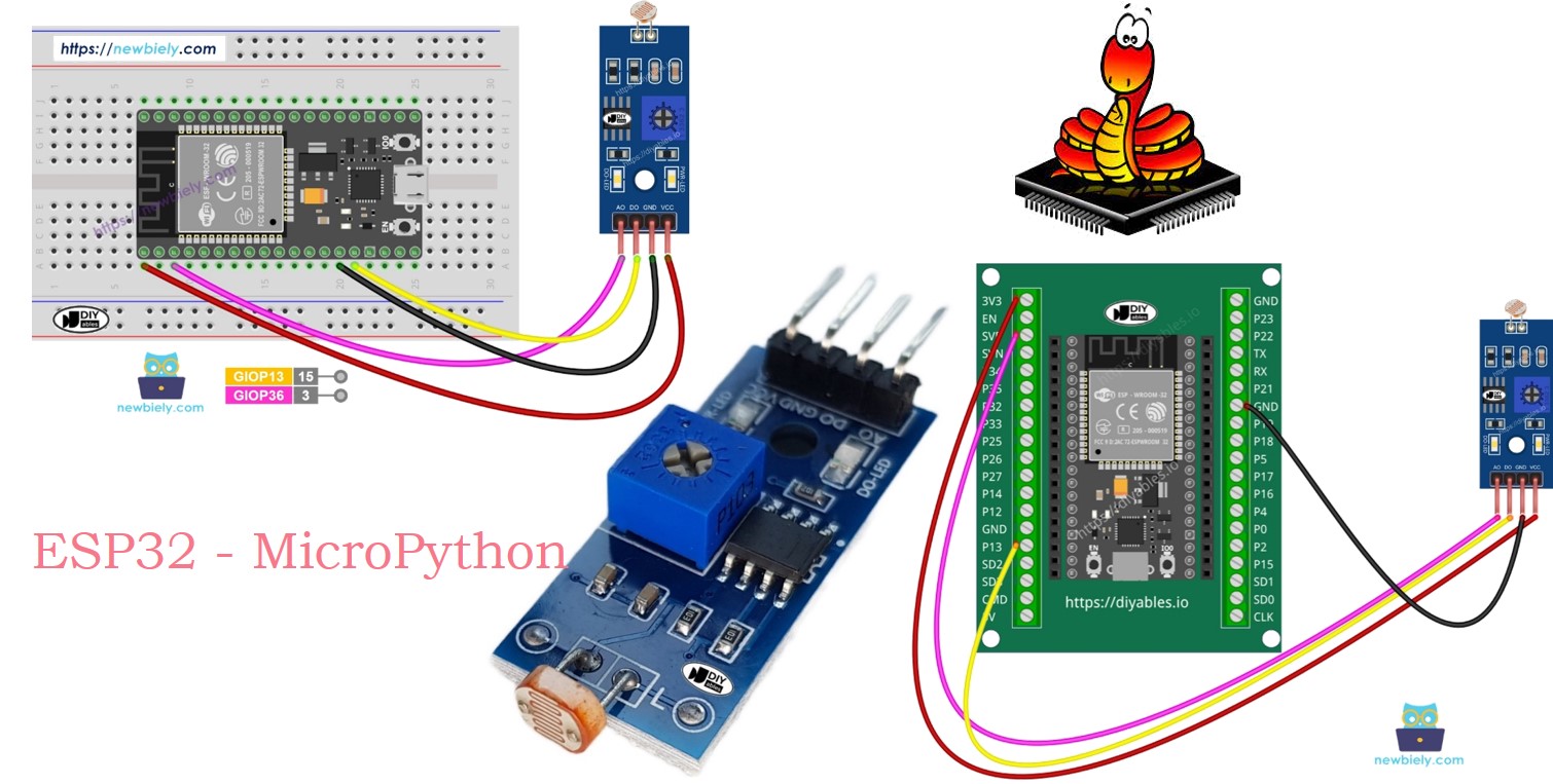
ESP32 MicroPython LDR Module
This tutorial instructs you you how to use a ESP32 and an LDR light sensor module to monitor and measure light levels. In detail, we will learn:
- How to connect the LDR light sensor module to a ESP32.
- How to write MicroPython code for the ESP32 to detect light with the LDR light sensor's digital signal.
- How to write MicroPython code for the ESP32 to measure light intensity using the LDR light sensor's analog signal.
Hardware Preparation
Or you can buy the following kits:
| 1 | × | DIYables ESP32 Starter Kit (ESP32 included) | |
| 1 | × | DIYables Sensor Kit (18 sensors/displays) |
Additionally, some of these links are for products from our own brand, DIYables .
Overview of LDR Light Sensor Module
The LDR light sensor module helps detect light or measure the amount of light around it. It provides two options: a digital output and an analog output.
Pinout
The LDR light sensor module comes with four pins:
- VCC pin: Attach this pin to VCC (3.3V to 5V).
- GND pin: Attach this pin to GND (0V).
- DO pin: This is a digital output pin. It shows HIGH in the dark and LOW in the light. Adjust the potentiometer to change the sensitivity to light and dark.
- AO pin: This is an analog output pin. The output value decreases in bright conditions and increases in dark conditions.
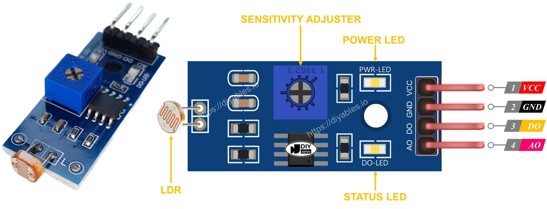
It also features two LED lights:
- A PWR-LED indicator lights up to show the power is on.
- A DO-LED indicator displays the light status on the DO pin: it lights up when there is light and turns off in the dark.
How It Works
DO Pin:
- The potentiometer adjusts the light threshold.
- DO pin is LOW (DO-LED off) when light is brighter than the threshold.
- DO pin is HIGH (DO-LED on) when light is dimmer than the threshold.
AO Pin:
- AO pin reading varies with light intensity.
- Lower reading means more light.
- Higher reading means darker conditions.
- Potentiometer does not affect AO pin value.
This method lets you adjust DO pin sensitivity with the potentiometer while getting accurate light measurements from the AO pin.
Wiring Diagram
The light sensor module offers two outputs, DO and AO, which can be used individually or together.
- How to connect ESP32 and ldr module using breadboard
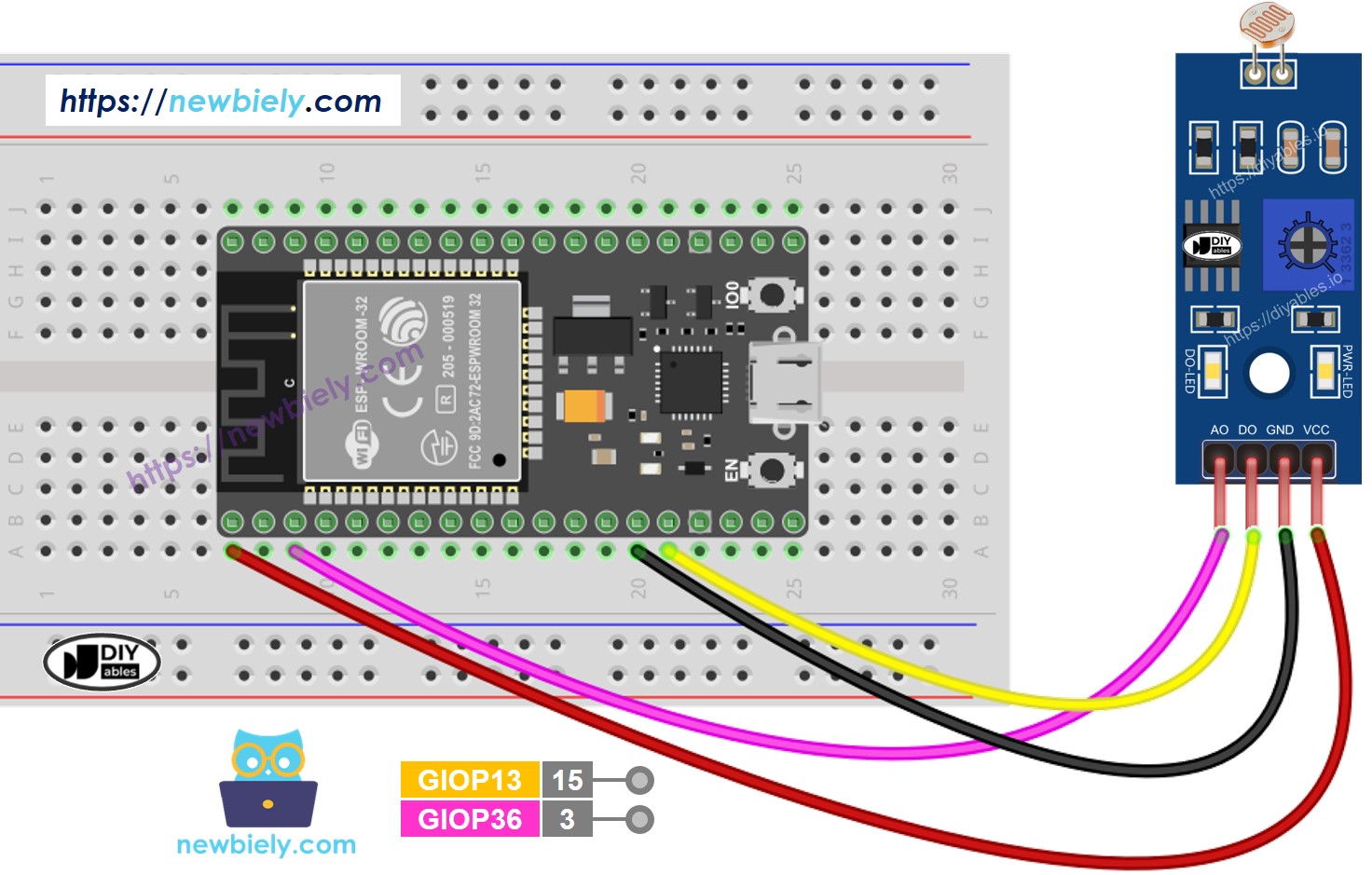
This image is created using Fritzing. Click to enlarge image
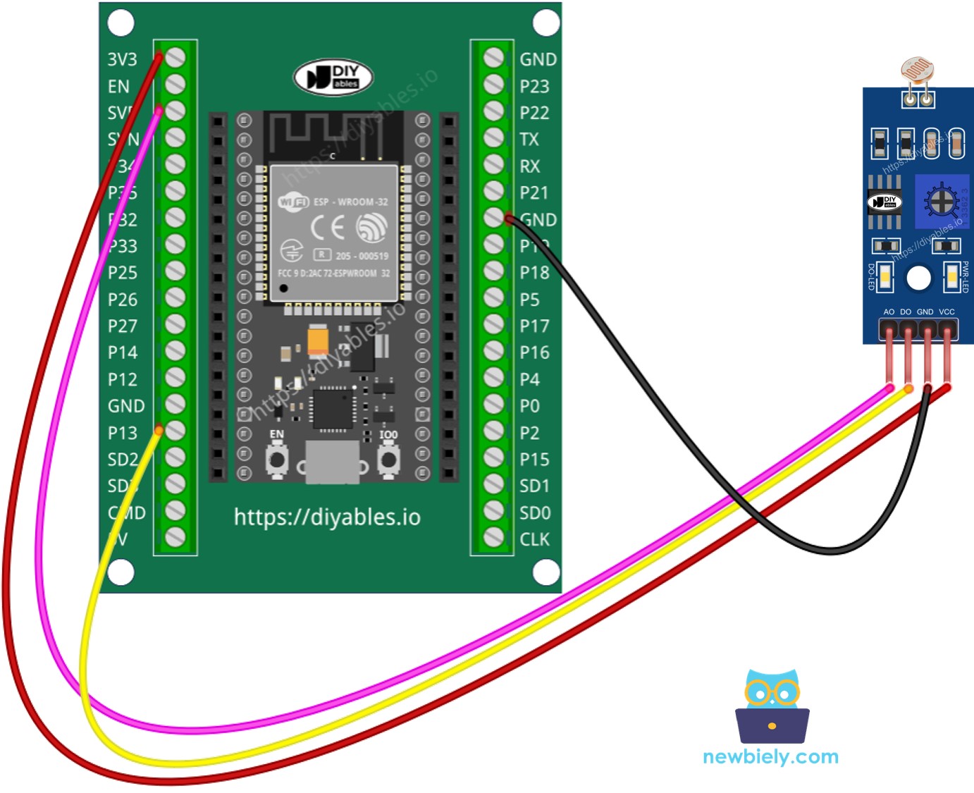
- How to connect ESP32 and ldr module using screw terminal block breakout board
ESP32 MicroPython Code - Read value from DO pin
Detailed Instructions
Here’s instructions on how to set up and run your MicroPython code on the ESP32 using Thonny IDE:
- Make sure Thonny IDE is installed on your computer.
- Confirm that MicroPython firmware is loaded on your ESP32 board.
- If this is your first time using an ESP32 with MicroPython, check out the ESP32 MicroPython Getting Started guide for step-by-step instructions.
- Connect the ESP32 the LDR module according to the provided diagram.
- Connect the ESP32 board to your computer with a USB cable.
- Open Thonny IDE on your computer.
- In Thonny IDE, go to Tools Options.
- Under the Interpreter tab, choose MicroPython (ESP32) from the dropdown menu.
- Make sure the correct port is selected. Thonny IDE usually detects it automatically, but you might need to select it manually (like COM12 on Windows or /dev/ttyACM0 on Linux).
- Copy the provided MicroPython code and paste it into Thonny\'s editor.
- Save the code to your ESP32 by:
- Clicking the Save button or pressing Ctrl+S.
- In the save dialog, choose MicroPython device.
- Name the file main.py.
- Click the green Run button (or press F5) to execute the script.
- Use your hand or an object to block and unblock the light on the LDR sensor module.
- Check out the message in the Shell at the bottom of Thonny.
If the LED is always on or off, adjust the light sensitivity using the potentiometer. You can now modify the code to control an LED, light switch, or servo motor based on light detection. For detailed instructions, refer to the tutorials at the end of this document.
※ NOTE THAT:
This tutorial demonstrates how to use the adc.read() function to read values from an ADC (Analog-to-Digital Converter) connected to a LDR module. The ESP32's ADC is suitable for projects that do not require high precision. However, if your project needs accurate measurements, keep the following in mind:
- The ESP32 ADC is not perfectly accurate and may require calibration for precise results. Each ESP32 board may vary slightly, so calibration is necessary for each individual board.
- Calibration can be challenging, especially for beginners, and might not always yield the exact results you desire.
For projects requiring high precision, consider using an external ADC (e.g., ADS1115) with the ESP32 or opt for an Arduino, which has a more reliable ADC. If you still wish to calibrate the ESP32 ADC, refer to the ESP32 ADC Calibration Driver.
ESP32 MicroPython Code - Read value from AO pin
Detailed Instructions
Please follow these instructions one by one:
- Copy the above code and open it in the Thonny IDE.
- Click the green Run button (or press F5) to run the script. The script will execute.
- Use your hand or an object to block and unblock the light on the LDR sensor module.
- Check out the message in the Shell at the bottom of Thonny.