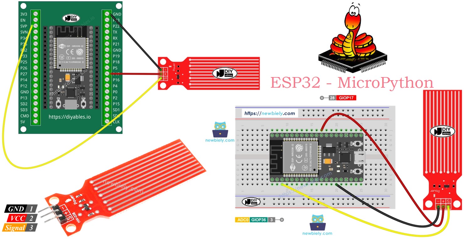
ESP32 MicroPython Water Sensor
This guide will show you how to use a water sensor with ESP32 and MicroPython to detect water leaks, measure rainfall, check if a tank is overflowed, or monitor water levels. In detail, we will learn.
- How to connect the water sensor to ESP32
- How to write MicroPython code for ESP32 to read values from the water sensor
- How to write MicroPython code for ESP32 to detect water leakage, rainfall, and tank overflow with ESP32
- How to write MicroPython code for ESP32 to measure water levels with ESP32
Hardware Preparation
Or you can buy the following kits:
| 1 | × | DIYables ESP32 Starter Kit (ESP32 included) | |
| 1 | × | DIYables Sensor Kit (18 sensors/displays) |
Additionally, some of these links are for products from our own brand, DIYables .
Overview of Water Level Sensor
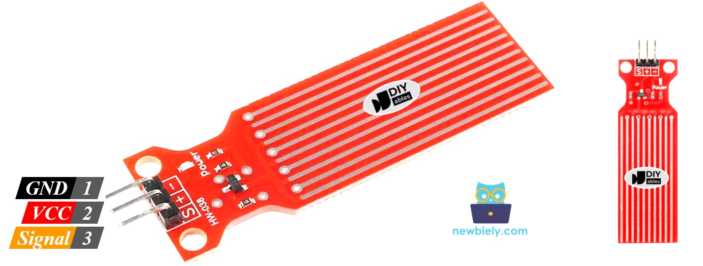
Water Level Sensor Pinout
The water level sensor has three pins:
- S (Signal) pin: Analog output. Connect to ESP32's analog input.
- + (VCC) pin: Provides power to the sensor. Use between 3.3V and 5V.
- - (GND) pin: Ground connection.
※ NOTE THAT:
The signal from the sensor changes when the voltage at its VCC pin is adjusted.
How Water Level Sensor Works
The sensor is made up of ten copper wires that you can see. Five of these wires are for power, and the other five are for sensing. They're arranged in a pattern, with one sensor wire between every two power wires. Normally, these wires don't touch, but when the sensor is in water, the water acts as a bridge between them.
Think of the wires like a special kind of knob that changes its resistance based on how much water is around it.
- The higher the water level, the lower the resistance.
- More water means better conductivity, which means lower resistance.
- Less water means poorer conductivity, which means higher resistance.
The sensor uses this resistance to create an output voltage. By measuring this voltage, we can figure out how high the water level is.
Wiring Diagram
Connect the sensor’s VCC pin to the 5V pin on the ESP32 and the GND pin to the GND pin on the ESP32 to power it. It’s not a good idea to keep the sensor powered on in a wet environment, as this can quickly damage it and shorten its lifespan. To avoid this, only power the sensor when you need to check its data. Connect the sensor’s VCC pin to a digital pin on the ESP32. To read the sensor, set the ESP32 pin to HIGH, and after reading, set it to LOW.
- How to connect ESP32 and water sensor using breadboard
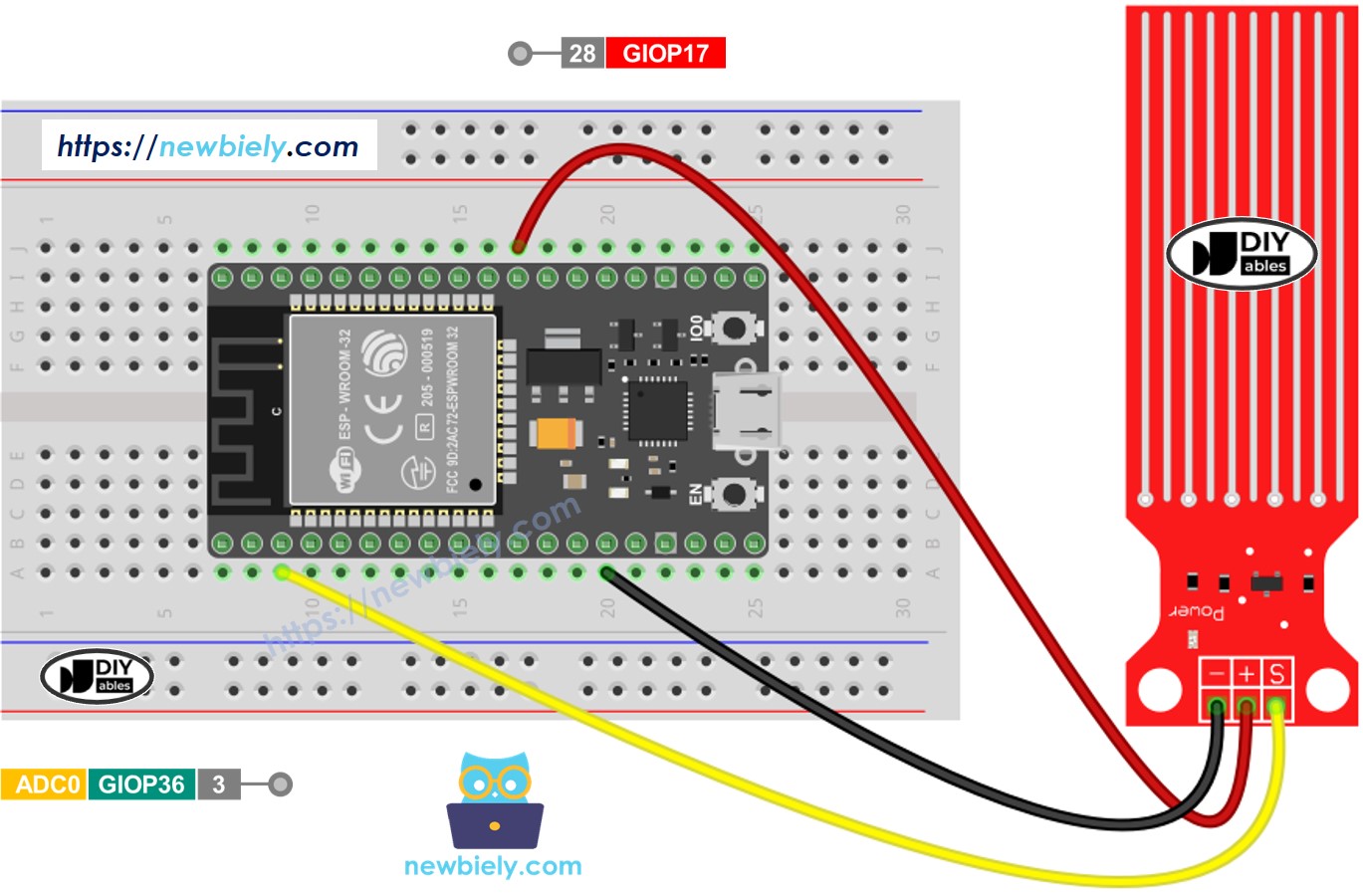
This image is created using Fritzing. Click to enlarge image
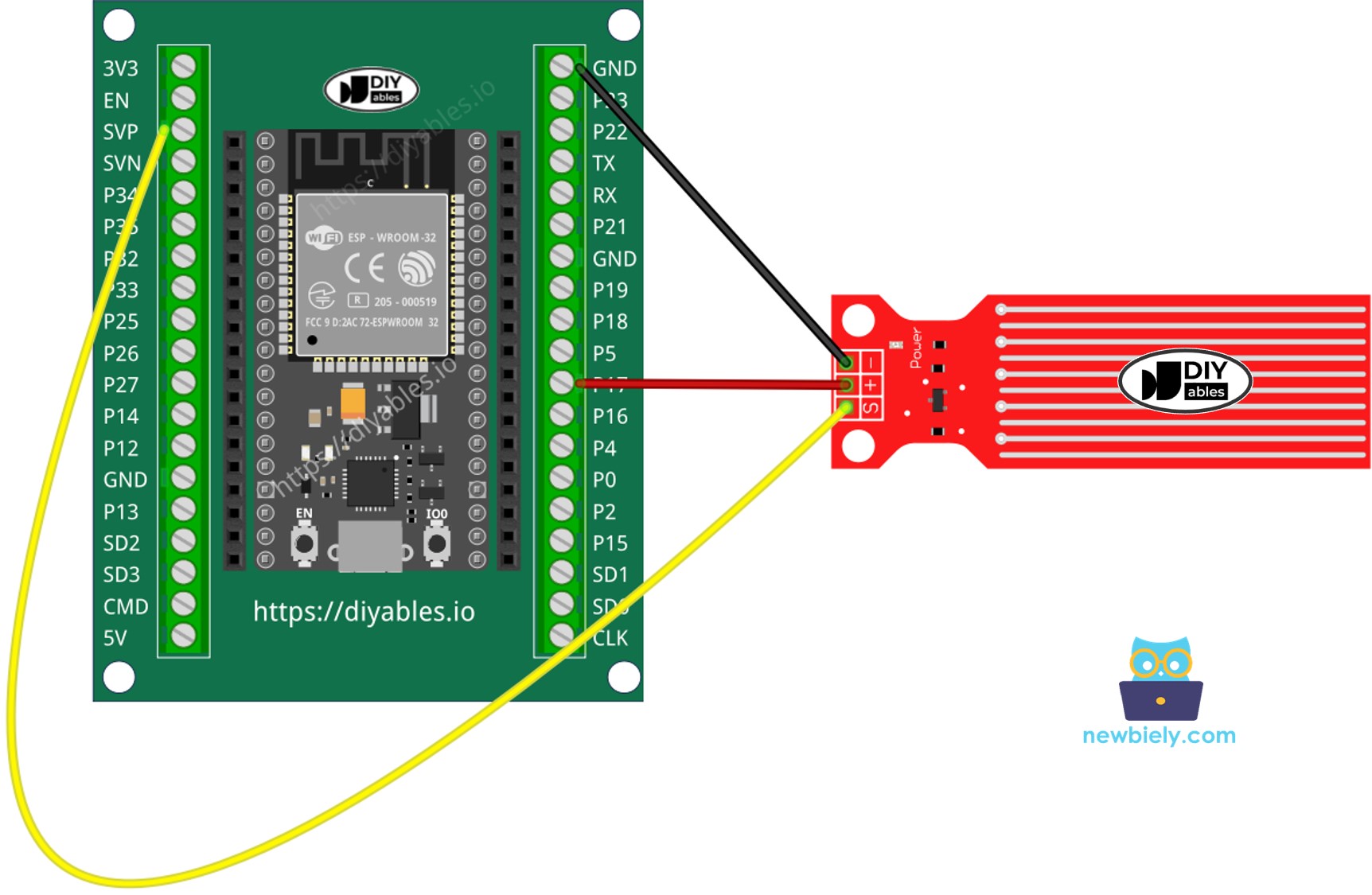
- How to connect ESP32 and water sensor using screw terminal block breakout board (powered via USB cable)
ESP32 MicroPython Code - Reading Value from Water Sensor
Detailed Instructions
Here’s instructions on how to set up and run your MicroPython code on the ESP32 using Thonny IDE:
- Make sure Thonny IDE is installed on your computer.
- Confirm that MicroPython firmware is loaded on your ESP32 board.
- If this is your first time using an ESP32 with MicroPython, check out the ESP32 MicroPython Getting Started guide for step-by-step instructions.
- Connect the ESP32 board to the water sensor according to the provided diagram.
- Connect the ESP32 board to your computer with a USB cable.
- Open Thonny IDE on your computer.
- In Thonny IDE, go to Tools Options.
- Under the Interpreter tab, choose MicroPython (ESP32) from the dropdown menu.
- Make sure the correct port is selected. Thonny IDE usually detects it automatically, but you might need to select it manually (like COM12 on Windows or /dev/ttyACM0 on Linux).
- Copy the provided MicroPython code and paste it into Thonny's editor.
- Save the code to your ESP32 by:
- Clicking the Save button or pressing Ctrl+S.
- In the save dialog, choose MicroPython device.
- Name the file main.py.
- Click the green Run button (or press F5) to execute the script.
- Slowly put the sensor into a glass of water.
- Check out the message in the Shell at the bottom of Thonny.
※ NOTE THAT:
Don't fully submerge the sensor; only let the visible parts of the electronic board touch the water. Be careful when installing it.
※ NOTE THAT:
This tutorial demonstrates how to use the adc.read() function to read values from an ADC (Analog-to-Digital Converter) connected to a water sensor. The ESP32's ADC is suitable for projects that do not require high precision. However, if your project needs accurate measurements, keep the following in mind:
- The ESP32 ADC is not perfectly accurate and may require calibration for precise results. Each ESP32 board may vary slightly, so calibration is necessary for each individual board.
- Calibration can be challenging, especially for beginners, and might not always yield the exact results you desire.
For projects requiring high precision, consider using an external ADC (e.g., ADS1115) with the ESP32 or opt for an Arduino, which has a more reliable ADC. If you still wish to calibrate the ESP32 ADC, refer to the ESP32 ADC Calibration Driver.
How To Detect Water Leakage
To check for water leaks, rain, or overflowing tanks, we compare the reading to a preset limit. This limit is set during the calibration part of this tutorial. The ESP32 MicroPython code below shows how to detect water leaks.
How To Measure The Water Level
To break down the highest water level into different stages and identify the current stage, follow the method in the code below. Keep in mind that the highest water level corresponds to the sensor being fully submerged in the water. This code splits the full height into 4 stages.
※ NOTE THAT:
- SENSOR_MIN and SENSOR_MAX are set during calibration.
- The mapping method explained may not be super precise, but it’s good enough for most uses. For better accuracy, measure the threshold values for each level as explained in the calibration section.
Water Level Sensor Calibration
The sensor’s output depends on both the water level and its conductivity. Pure water doesn’t conduct electricity, but water with minerals and impurities does. The more conductive the water, the more sensitive the sensor becomes. Additionally, the output can change based on the voltage supplied to the sensor's VCC pin.
For accurate readings from the water sensor, it’s best to calibrate it for the specific type of water you plan to monitor. Before setting a threshold to trigger an action, you should test the actual value the sensor reads.
How to perform the test:
- Use the sketch above to read the sensor's value.
- Dip the sensor into the water at the level where you want to set the threshold.
- Write down the value shown in the Shell at the bottom of Thonny.
- Use this value as the threshold to trigger an action.
- You might need to try this test a few times to get it right.
The test can also help you find:
- The SENSOR_MIN value, when the sensor isn’t in water.
- The SENSOR_MAX value, when the sensor is fully submerged.
- A threshold value to detect water leaks.
- Threshold values for different levels on your scale.