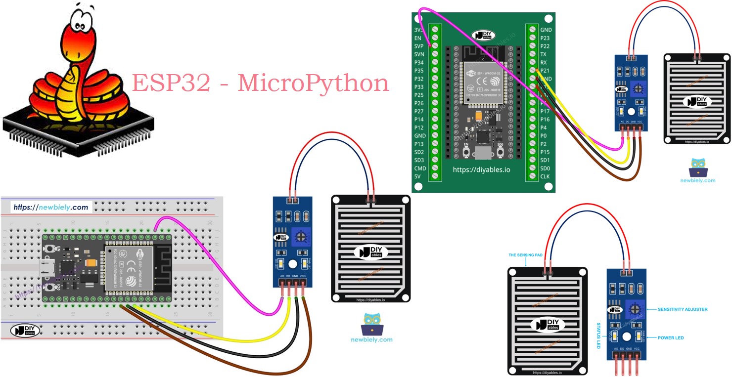
ESP32 MicroPython Rain Sensor
This tutorial instructs you how to use a rain sensor with a ESP32 and MicroPython to detect rain or snow. We will learn the followings:
- How to connect a rain sensor to a ESP32.
- How to write MicroPython code for ESP32 to detect rain using a digital signal from the rain sensor.
- How to write MicroPython code for ESP32 to measure how heavy the rain is using an analog signal from the rain sensor.
You can modify the code so that it activates a motor or an alarm when it detects rain or snow.
Hardware Preparation
Or you can buy the following kits:
| 1 | × | DIYables ESP32 Starter Kit (ESP32 included) | |
| 1 | × | DIYables Sensor Kit (18 sensors/displays) |
Additionally, some of these links are for products from our own brand, DIYables .
Overview of Rain Sensor
The rain sensor can detect and measure the amount of rain or snow that falls. It provides two types of output signals: a digital signal (LOW or HIGH) and an analog signal.
The rain sensor is composed of two parts:
- The sensor pad
- The electronic module
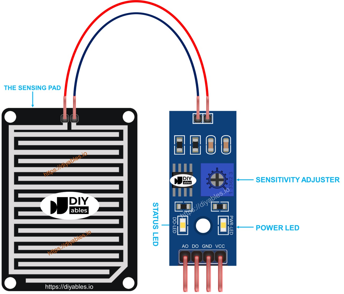
The Sensing Pad
The sensing pad is placed outside, where it can be exposed to rain or snow, such as on a roof. It consists of multiple copper lines, which are divided into two types: power lines and sensor lines. These lines remain separate and only connect when water or snow touches them. Both types of lines function identically, so you can designate any line as the power line and another as the sensor line.
The Electronic Module
The electronic module of the rain sensor converts the signal from the sensing pad into a form (analog or digital) that the ESP32 can interpret. It has four pins:
- VCC pin: Connects to VCC (between 3.3V and 5V).
- GND pin: Connects to GND (0V).
- DO pin: A digital output pin that goes HIGH when there is no rain and LOW when rain is detected. The potentiometer can be adjusted to change the rain detection sensitivity.
- AO pin: An analog output pin where the output value decreases as more water accumulates on the sensing pad and increases as the water lessens.
The module also includes two LED indicators:
- A power indicator (PWR-LED) that lights up when the module is powered on.
- A rain status indicator (DO-LED) connected to the DO pin, which lights up when rain is detected.
How It Works
For the DO pin:
- The module includes a potentiometer to adjust sensitivity.
- When the rain level is high, the sensor's output pin goes LOW, and the DO-LED light turns on.
- When the rain level is low, the sensor's output pin stays HIGH, and the DO-LED light remains off.
Regarding the AO pin:
- As the sensing pad detects more water, the AO pin value decreases.
- As the sensing pad detects less water, the AO pin value increases.
- The potentiometer does not affect the AO pin value.
Wiring Diagram
Connect the sensor's VCC pin to a 3.3V or 5V pin on the ESP32. However, a direct connection could reduce the sensor's lifespan due to electrochemical corrosion. Instead, connect the VCC pin to a programmable output pin on the ESP32, providing power to the sensor only when taking readings. This approach helps reduce electrochemical corrosion.
- How to connect ESP32 and rain sensor using breadboard
The rain sensor module offers two outputs. You can use either one or both as required.
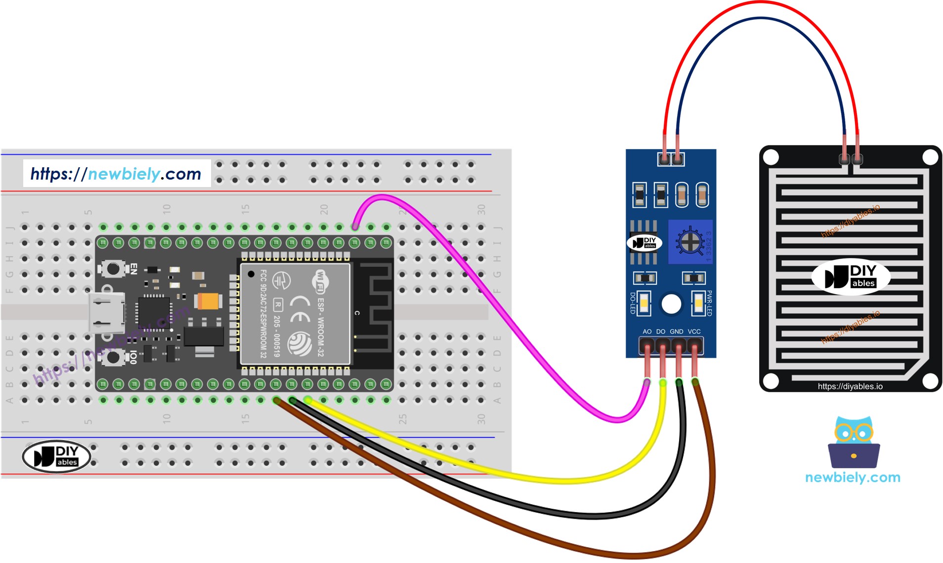
This image is created using Fritzing. Click to enlarge image
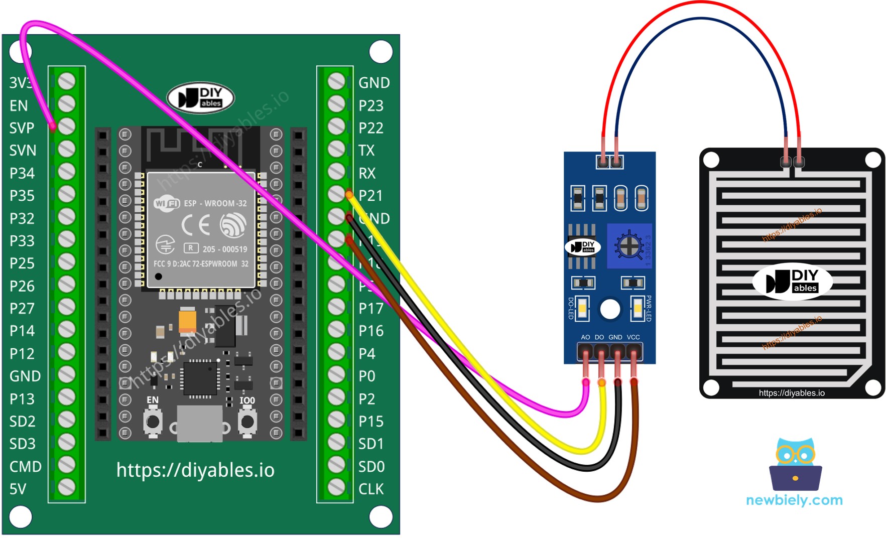
- How to connect ESP32 and rain sensor using screw terminal block breakout board
ESP32 MicroPython Code - Read value from DO pin
Detailed Instructions
Here’s instructions on how to set up and run your MicroPython code on the ESP32 using Thonny IDE:
- Make sure Thonny IDE is installed on your computer.
- Confirm that MicroPython firmware is loaded on your ESP32 board.
- If this is your first time using an ESP32 with MicroPython, check out the ESP32 MicroPython Getting Started guide for step-by-step instructions.
- Connect the ESP32 board to the rain sensor according to the provided diagram.
- Connect the ESP32 board to your computer with a USB cable.
- Open Thonny IDE on your computer.
- In Thonny IDE, go to Tools Options.
- Under the Interpreter tab, choose MicroPython (ESP32) from the dropdown menu.
- Make sure the correct port is selected. Thonny IDE usually detects it automatically, but you might need to select it manually (like COM12 on Windows or /dev/ttyACM0 on Linux).
- Copy the provided MicroPython code and paste it into Thonny's editor.
- Save the code to your ESP32 by:
- Clicking the Save button or pressing Ctrl+S.
- In the save dialog, choose MicroPython device.
- Name the file main.py.
- Click the green Run button (or press F5) to execute the script.
- Place some water drops on the rain sensor. Do not use pure water.
- Check out the message in the Shell at the bottom of Thonny.
Please note, if the LED light remains constantly on or stays off even during rain, adjust the sensor's sensitivity by changing the potentiometer.
ESP32 MicroPython Code - Read value from AO pin
Detailed Instructions
- Copy the code and open it in Thonny IDE.
- Click the green Run button (or press F5) to run the script. The script will execute.
- Put some water on the rain sensor.
- Check out the message in the Shell at the bottom of Thonny.
※ NOTE THAT:
This tutorial demonstrates how to use the adc.read() function to read values from an ADC (Analog-to-Digital Converter) connected to a rain sensor. The ESP32's ADC is suitable for projects that do not require high precision. However, if your project needs accurate measurements, keep the following in mind:
- The ESP32 ADC is not perfectly accurate and may require calibration for precise results. Each ESP32 board may vary slightly, so calibration is necessary for each individual board.
- Calibration can be challenging, especially for beginners, and might not always yield the exact results you desire.
For projects requiring high precision, consider using an external ADC (e.g., ADS1115) with the ESP32 or opt for an Arduino, which has a more reliable ADC. If you still wish to calibrate the ESP32 ADC, refer to the ESP32 ADC Calibration Driver.