ESP32 MicroPython Relay
This tutorial instructs you how to use a ESP32 and MicroPython to control a relay module. In detail, we will learn:
- How a relay works.
- How to connect a relay to a high-voltage device.
- How to connect the ESP32 to the relay.
- How to write MicroPython code for the ESP32 to control the relay for switching high-voltage devices on and off.
Hardware Preparation
Or you can buy the following kits:
| 1 | × | DIYables ESP32 Starter Kit (ESP32 included) | |
| 1 | × | DIYables Sensor Kit (18 sensors/displays) |
Additionally, some of these links are for products from our own brand, DIYables .
Overview of Relay
A relay is a programmable switch that can be controlled by devices like the ESP32 or other microcontrollers. It enables automated control of devices, particularly those requiring high voltage or high current, by switching them on or off. Essentially, the relay acts as an intermediary between the ESP32 and high-voltage devices.
WARNING
When working with electricity, safety is crucial. Be careful to avoid electric shocks. If you're unsure about anything, ask for help from someone who knows what they're doing.
We recommend using a DC device (up to 24V) for testing, even though some relays can work with both DC and AC devices.
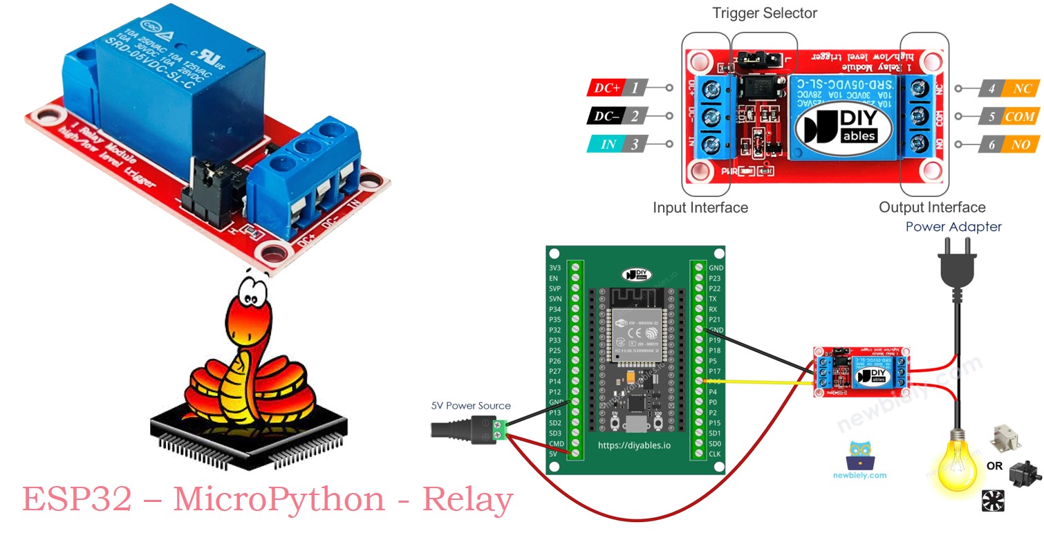
Relay Pinout
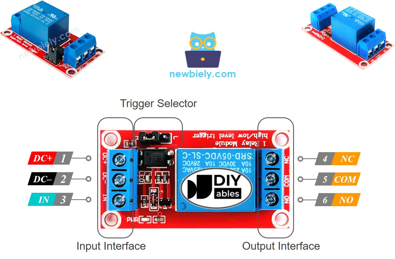
A relay has two groups of pins: the input pins that work with low voltage, and the output pins that work with high voltage.
- Connect the pins in the input group to the ESP32. There are three pins:
- DC- pin: connect to GND (0V).
- DC+ pin: connect to VCC (5V).
- IN pin: connect this pin to receive the control signal from the ESP32.
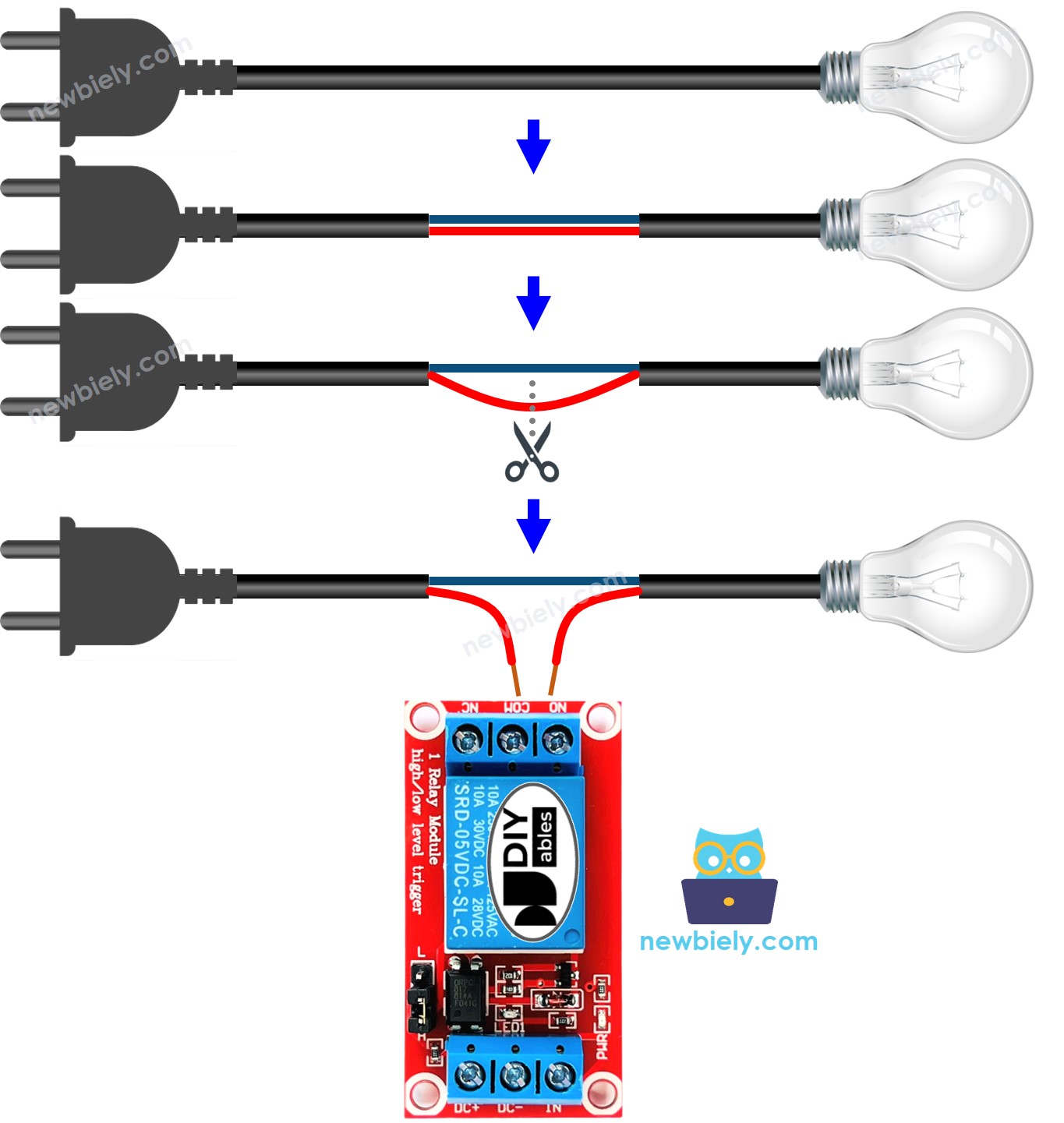
- Connect the pins in the output group to the high-voltage device. There are also three pins, typically found in a screw terminal:
- COM pin: this is the common connection used in both the normally open and normally closed modes.
- NO pin: this is the normally open pin. Use it in the normally open setting.
- NC pin: this is the normally closed pin. Use it in the normally closed mode.
- In normally open mode, connect just the COM pin and the NO pin.
- In normally closed mode, connect just the COM pin and the NC pin.
- LOW level trigger mode
- HIGH level trigger mode
- Open by default mode
- Closed by default mode.
- The "normally open" mode and "normally closed" mode function differently.
- Many relay modules can use both "normally open" and "normally closed" modes.
- The LOW level trigger mode and "HIGH level level trigger" mode function differently.
- Not all relay modules can use both LOW level trigger and HIGH level trigger modes.
- A relay module can only work in one mode at a time, either LOW level trigger or HIGH level trigger.
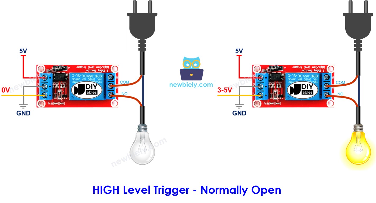
- If the IN pin is connected to LOW (0V), the switch stays open, and the device is turned OFF.
- If the IN pin is connected to HIGH (5V), the switch is closed, and the device is turned ON.
- When the IN pin is connected to LOW (0V), the switch is closed. This means the device is turned on.
- When the IN pin is connected to HIGH (5V), the switch is open. This means the device is turned off.
- Connect the pin on the ESP32 to the IN pin on the relay.
- Set the pin to LOW or HIGH to control the relay.
We typically use only two of the pins in the high voltage group, not all of them.
Additionally, if the relay supports both LOW and HIGH level triggers, there's usually a jumper to select either the LOW level trigger or the HIGH level trigger.
※ NOTE THAT:
Different manufacturers might arrange the pins on the relay module differently. Always carefully check the labels on your relay for the correct pin connections. Pay close attention to the pin placements!
How to Connect the High Voltage Device to Relay
How It Works
A relay can work differently based on the manufacturer and the installation method used by the user.
The input mode: There are two input modes that make the relay work in opposite ways:
The output mode: There are two output modes, and they make the relay function differently:
The word "normally" means when the "IN pin" is connected to "LOW (0V)". Here is some basic information:
The mix of input modes and output modes creates several use cases. For beginners, we recommend using HIGH level trigger mode and normally open mode.
The LOW level trigger and HIGH level trigger modes work differently. Next, we will explain the HIGH level trigger mode in detail. The LOW level trigger works in the opposite way.
HIGH Level Trigger - Normally Open Mode
To activate this mode, connect the high voltage device to both the COM pin and the NO pin.
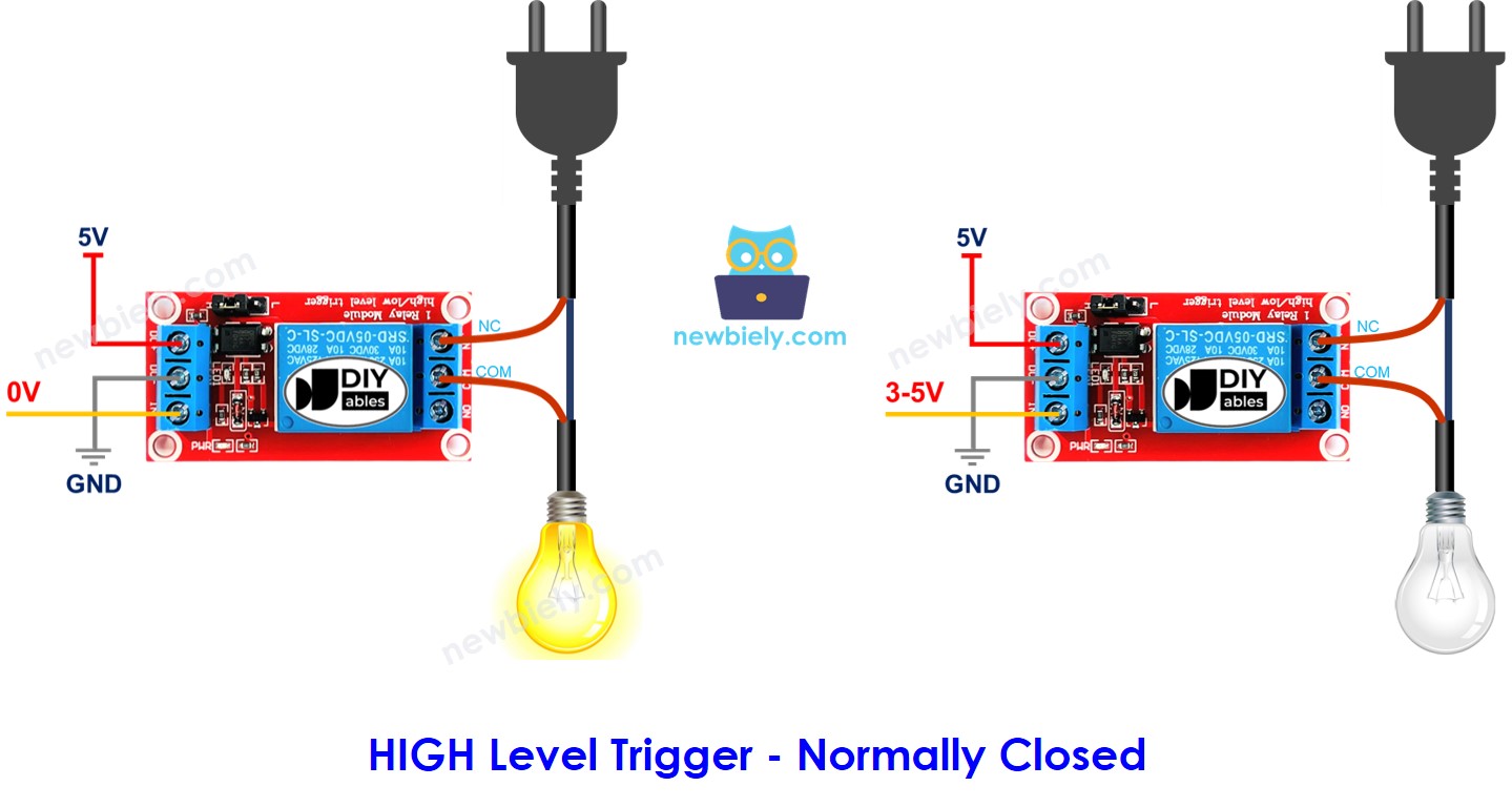
HIGH Level Trigger - Normally Closed Mode
To use this mode, connect the high voltage device to the COM pin and the NC pin.
Summary
| Input modes | Output modes | IN pin (programmable) | Output pins | Relay state | Device state |
|---|---|---|---|---|---|
| HIGH Trigger | Normally Open | LOW | COM and NO pin | ⇒ open | ⇒ OFF |
| HIGH Trigger | Normally Open | HIGH | COM and NO pin | ⇒ closed | ⇒ ON |
| HIGH Trigger | Normally Closed | LOW | COM and NC pin | ⇒ closed | ⇒ ON |
| HIGH Trigger | Normally Closed | HIGH | COM and NC pin | ⇒ open | ⇒ OFF |
| LOW Trigger | Normally Open | LOW | COM and NO pin | ⇒ closed | ⇒ ON |
| LOW Trigger | Normally Open | HIGH | COM and NO pin | ⇒ open | ⇒ OFF |
| LOW Trigger | Normally Closed | LOW | COM and NC pin | ⇒ open | ⇒ OFF |
| LOW Trigger | Normally Closed | HIGH | COM and NC pin | ⇒ closed | ⇒ ON |
There can be up to 8 use cases. This may look too much. But if you are starting out, just concentrate on the first two cases. These include the HIGH level trigger and the normally open settings. We will mostly discuss these two cases in this tutorial.
ESP32 - Relay
The ESP32 uses a relay to manage a device that works with high voltage.
Controlling a relay is simple. We only need:
Wiring Diagram
- How to connect ESP32 and relay using breadboard (powered via USB cable)
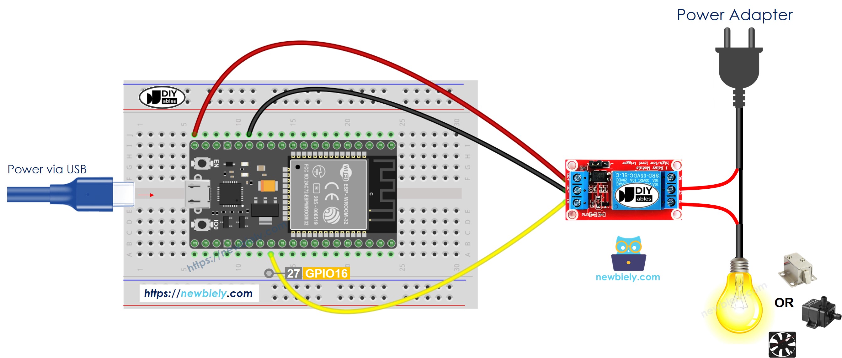
This image is created using Fritzing. Click to enlarge image
- How to connect ESP32 and relay using breadboard (powered via Vin pin)
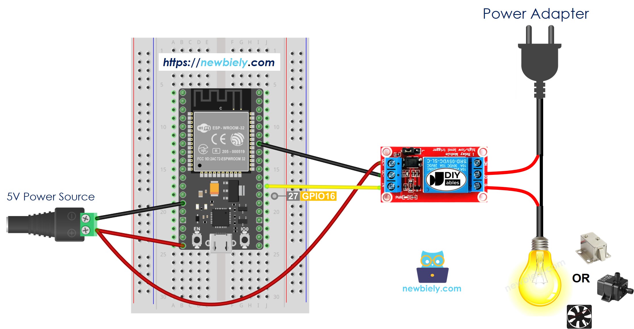
This image is created using Fritzing. Click to enlarge image
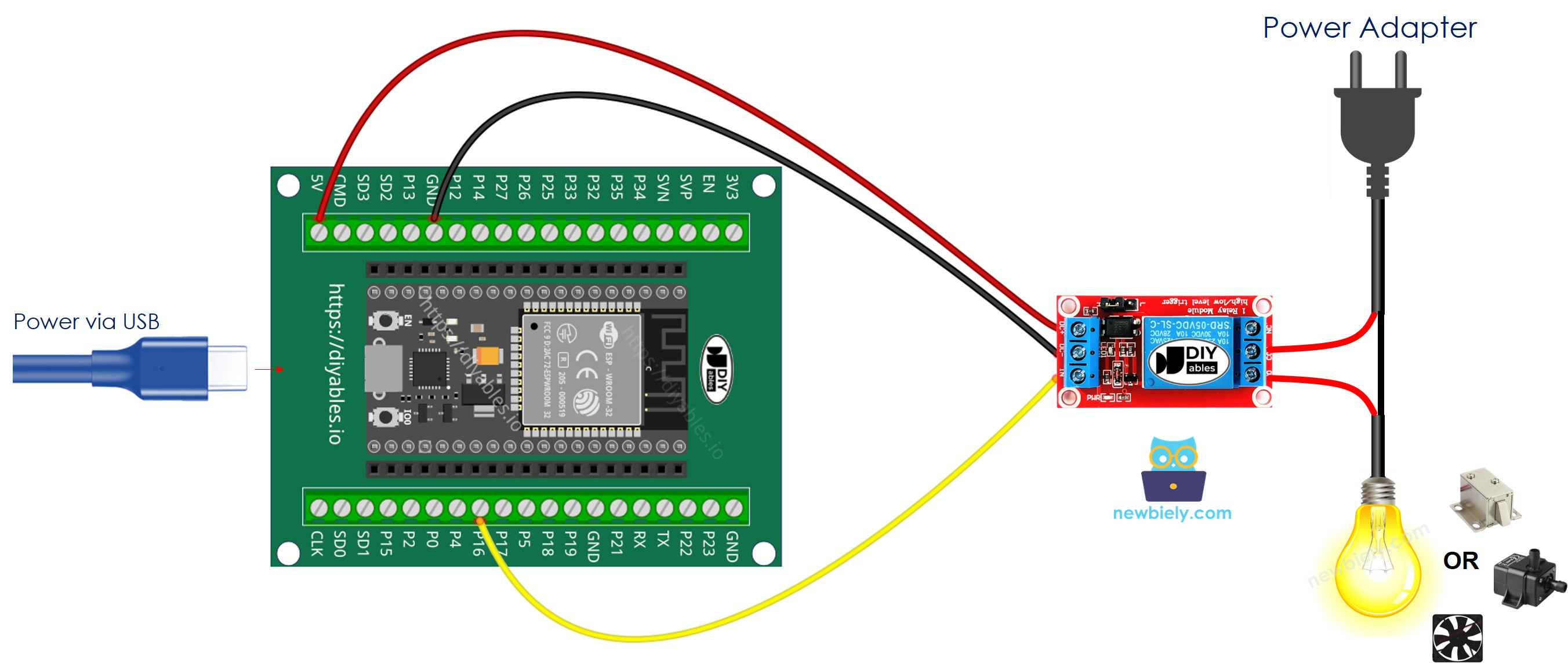
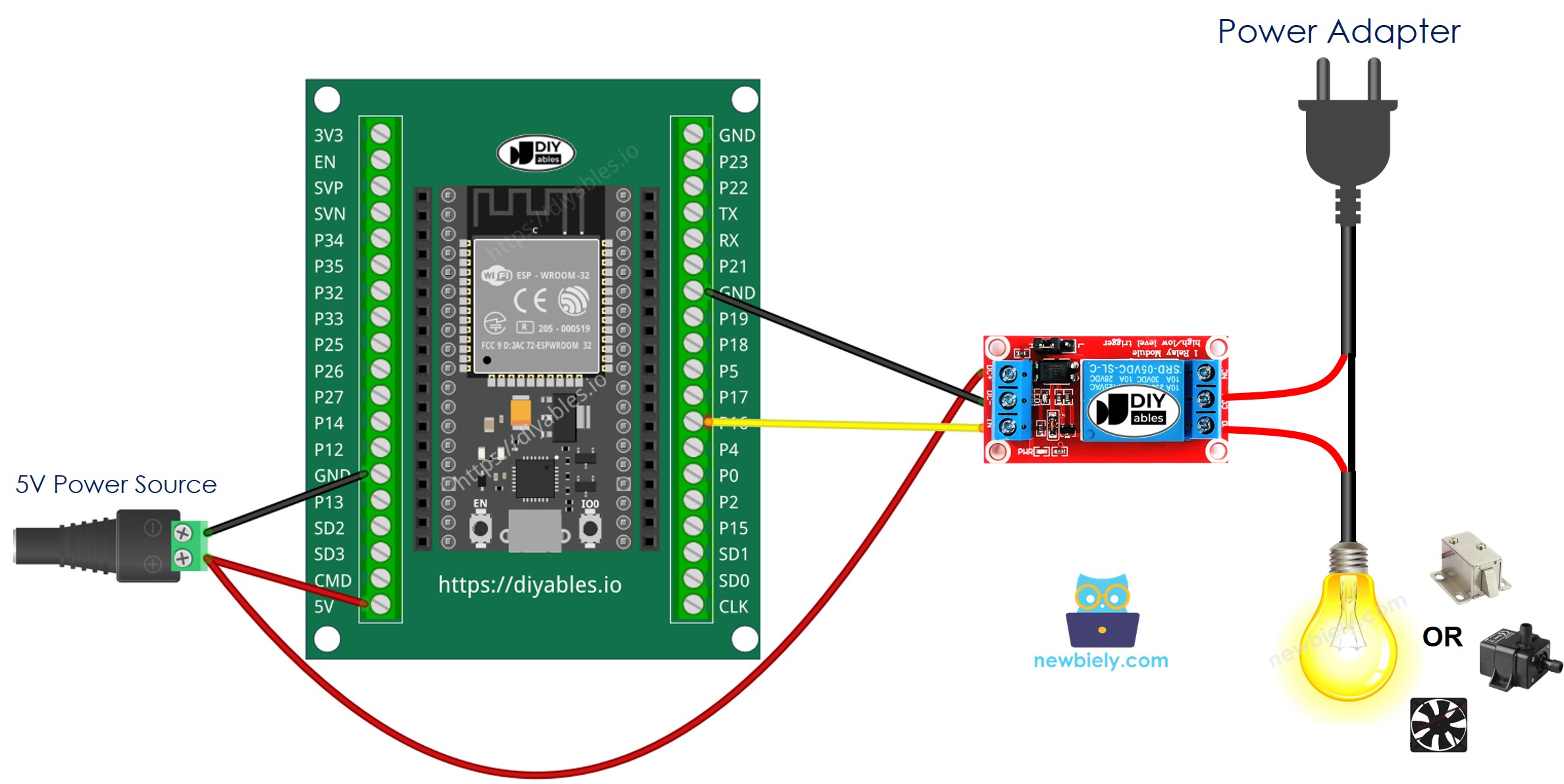
- How to connect ESP32 and relay using screw terminal block breakout board (powered via USB cable)
- How to connect ESP32 and relay using screw terminal block breakout board (powered via Vin pin)
How To Program For Relay
- To configure a ESP32 pin as a digital output. For example, to set up pin 3, use this function.
- Turn on relay.
- Turn off relay.
ESP32 MicroPython Code
Detailed Instructions
Here’s instructions on how to set up and run your MicroPython code on the ESP32 using Thonny IDE:
- Make sure Thonny IDE is installed on your computer.
- Confirm that MicroPython firmware is loaded on your ESP32 board.
- If this is your first time using an ESP32 with MicroPython, check out the ESP32 MicroPython Getting Started guide for step-by-step instructions.
- Connect the ESP32 board to the relay according to the provided diagram.
- Connect the ESP32 board to your computer with a USB cable.
- Open Thonny IDE on your computer.
- In Thonny IDE, go to Tools Options.
- Under the Interpreter tab, choose MicroPython (ESP32) from the dropdown menu.
- Make sure the correct port is selected. Thonny IDE usually detects it automatically, but you might need to select it manually (like COM12 on Windows or /dev/ttyACM0 on Linux).
- Copy the provided MicroPython code and paste it into Thonny\'s editor.
- Save the code to your ESP32 by:
- Clicking the Save button or pressing Ctrl+S.
- In the save dialog, choose MicroPython device.
- Name the file main.py.
- Click the green Run button (or press F5) to execute the script.
- Check out the relay state.