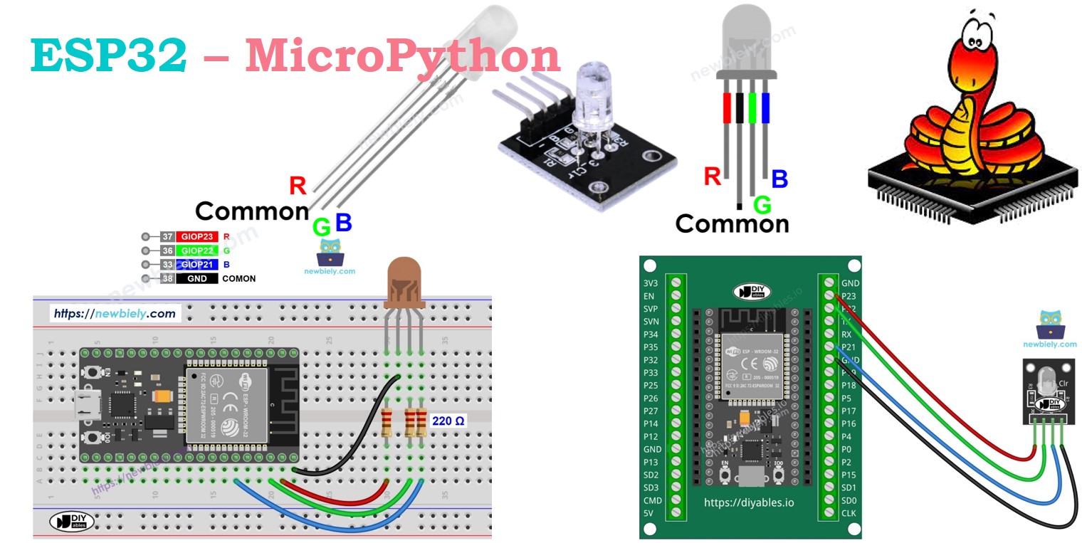
ESP32 MicroPython RGB LED
This guide shows you how to control an RGB LED using a ESP32 and MicroPython. We will cover:
- How to control RGB LED
- How to connect RGB LED to ESP32
- How to connect RGB LED module to ESP32
- How to write MicroPython code for ESP32 to control the color of RGB LED
Hardware Preparation
Or you can buy the following kits:
| 1 | × | DIYables ESP32 Starter Kit (ESP32 included) | |
| 1 | × | DIYables Sensor Kit (18 sensors/displays) |
Additionally, some of these links are for products from our own brand, DIYables .
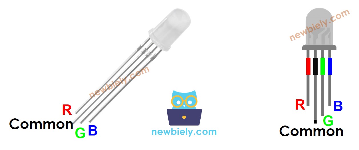
Overview of RGB LED
The RGB LED can make any color by combining red, green, and blue, the three basic colors. It has three different LEDs - one red, one green, and one blue - all in a single unit.
Pinout
An RGB LED comes with four pins.
- Attach the Common (Cathode-) pin to GND (0V).
- The R (red) pin manages the red color.
- The G (green) pin manages the green color.
- The B (blue) pin manages the blue color.
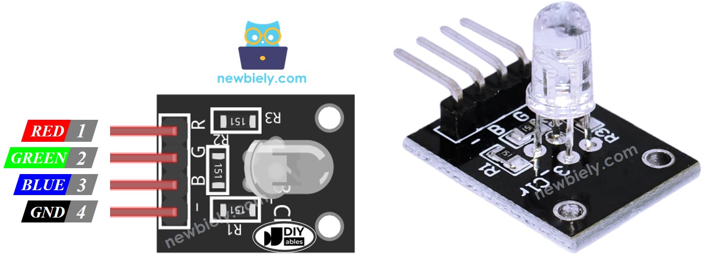
To connect an RGB LED to a ESP32, it's better to use resistors that control the current, making the process complex. But, you can use the RGB LED module which already includes these resistors.
The RGB LED module also has four pins.
- Connect the Common (Cathode-) pin to GND (0V).
- The R (red) pin controls the red color.
- The G (green) pin controls the green color.
- The B (blue) pin controls the blue color.
※ NOTE THAT:
This guide shows how to use an RGB LED that has a common cathode. This means the cathode is the common pin. Some RGB LEDs might have the anode as the common pin.
How it works
In physics, a color consists of three values: Red (R), Green (G), and Blue (B). These values range from 0 to 255.
There are 16,777,216 colors made by mixing three different values.
By sending PWM signals (with a duty bit range from 0 to 255) to the R, G, and B pins, we can cause the RGB LED to show any color. The PWM duty cycle directed to the R, G, and B pins corresponds to the respective color values for Red (R), Green (G), and Blue (B).
Wiring Diagram
- How to connect ESP32 and RGB LED using breadboard
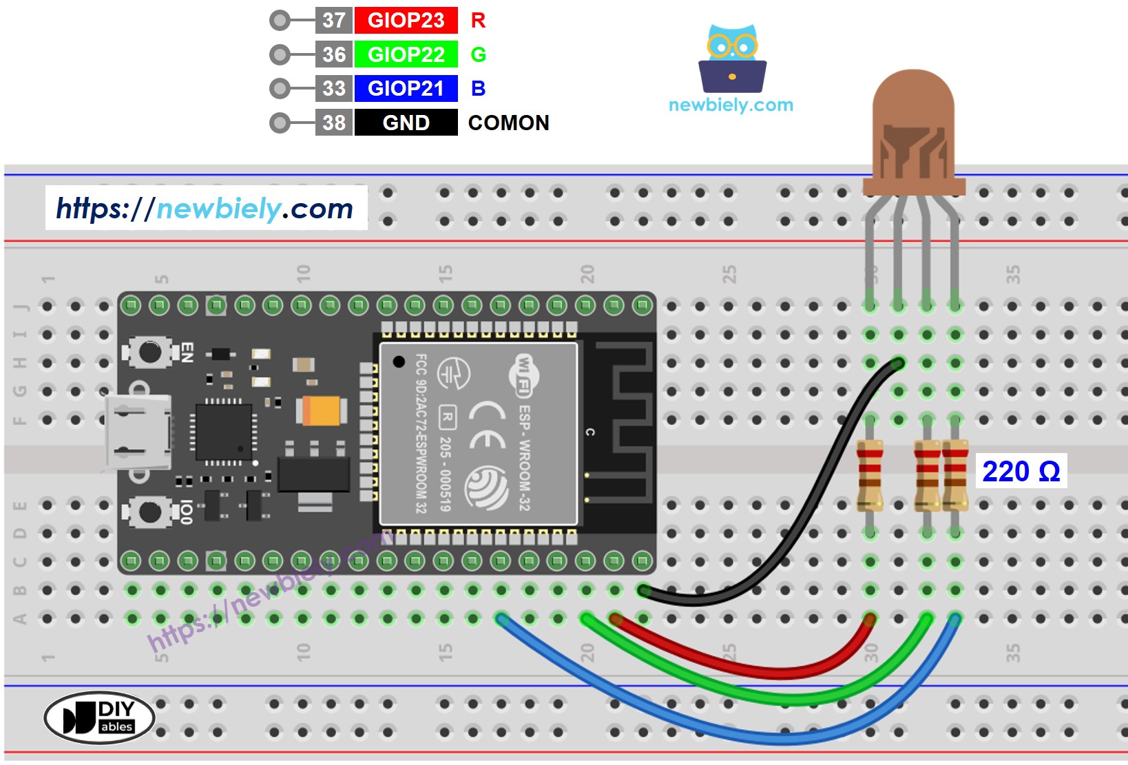
This image is created using Fritzing. Click to enlarge image
Do not connect just one resistor to the common pin of an RGB LED. You should connect three different resistors, one to each of the other pins as shown in the diagram. The LEDs in the RGB package have different characteristics, so they do not use the same amount of current. This difference can make the LEDs shine with uneven brightness and might even harm them if only one resistor is used on the common pin.
- How to connect a ESP32 to RGB LED module using screw terminal block breakout board:
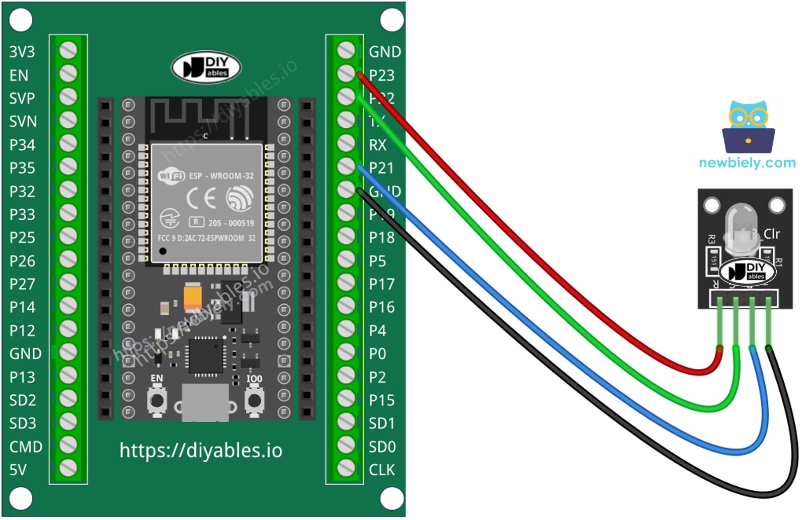
This image is created using Fritzing. Click to enlarge image
How To Control RGB LED
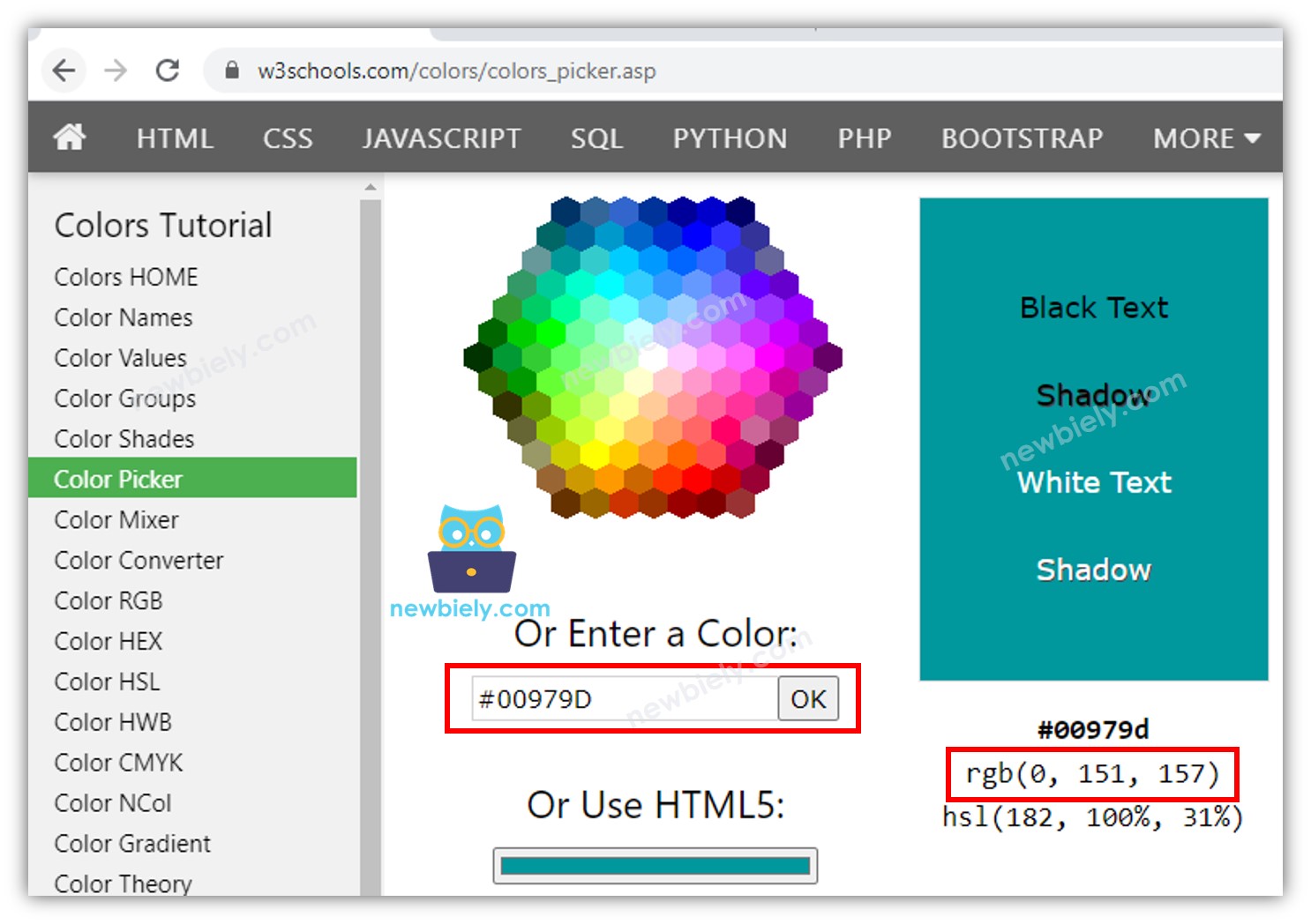
Let's learn how to change the RGB LED to a specific color, like #00979D, step by step.
- Pick your preferred color and get its color code.
- Use this color code selector: color picker.
- To extract a color code from a photograph, try this tool: Colors From Image.
- Change the color code to RGB format with this converter: RGB converter. Note these numbers: R = 0, G = 151, B = 157.
- Define the ESP32 pins that connect to the R (red), G (green), and B (blue) pins. For example:
- Set these ESP32 pins to output mode.
- Set the PWM frequency to 1000 Hz
- Set the PWM duty cycle
ESP32 - RGB LED Example Code
The code below alters the color of the LED in this sequence:
- #00C9CC (Red = 0, Green = 201, Blue = 204)
- #F7788A (Red = 247, Green = 120, Blue = 138)
- #34A853 (Red = 52, Green = 168, Blue = 83)