
Arduino MicroPython PC817 Optocoupler: Monitor 12V/24V DC Input Signal
An Arduino running MicroPython lives in a 3.3V world, so touching one of its pins with a 12V or 24V wire is the fastest way to end a project. A PC817 optocoupler removes that danger completely: the outside voltage never reaches the board, it only sends light across a sealed gap. The quickest way to get that gap is a ready-made PC817 optocoupler isolation module, which arrives with its resistor and its screw terminals already fitted - as long as you order the variant that matches your signal, because one module does not cover every voltage. Once the gap is there, the board can answer the question that usually brought you here in the first place - is the shutter motor, the lift, the pump or the panel lamp actually on right now? - by watching the device's own supply instead of guessing. In this guide you will learn:
- Which of the three PC817 optocoupler module variants - 3-5V, 12V and 24V - matches the signal you want to watch.
- How to wire that module to an Arduino running MicroPython, and how to find out whether yours reads active LOW or active HIGH.
- How to hang the module in parallel across a device so the Arduino can tell whether that device is on or off, without altering the device's own wiring.
- How to write MicroPython code for the Arduino to read the isolated digital input, with the polarity kept in a single constant.
- How to write MicroPython code for the Arduino to report the exact moment the external signal appears and disappears.
- How to build the same isolated input out of the bare 4-pin PC817 chip and a resistor, if you would rather.
Hardware Preparation
Or you can buy the following kits:
| 1 | × | DIYables Sensor Kit (18 sensors/displays) |
Additionally, some of these links are for products from our own brand, DIYables .
Overview of PC817 Optocoupler
The PC817 is a 4-pin DIP part that people also call a photocoupler, an opto-isolator or simply an optoisolator. Inside its black plastic body there is an infrared LED aimed at a phototransistor across an insulating gap. When current flows through the LED, its light switches the transistor on, so the signal crosses as light instead of electricity - and that is exactly why the two sides never share a wire. That gap is rated for 5000 Vrms for one minute.
Whether you buy the chip on its own or already soldered onto a module, the same silicon does the work, so the same numbers apply:
- The input LED drops about 1.2 V (1.4 V worst case) and wants 5 to 20 mA, with 10 mA being a comfortable target. 20 mA continuous is the ceiling. Something has to limit that current, which is the whole reason ready-made modules are sold in voltage variants.
- The output transistor handles up to 35 V between collector and emitter and up to 50 mA of collector current, dissipating at most 150 mW - far more headroom than the 3.3V logic of the Arduino Giga R1 WiFi will ever ask for.
- Current Transfer Ratio (CTR) runs from 50% to 600% depending on the rank of the part: rank A is 80-160%, rank B 130-260%, rank C 200-400%, rank D 300-600%.
- Rise time is around 4 us and fall time around 3 us, which is instant compared with any 12V or 24V machine signal.
- The part is rated from -30 C to +100 C.
Two jobs suit this part particularly well, and both come back later in this tutorial:
- Watching a 24V limit line on a roller shutter, a gate or a small goods lift, where the top and bottom limit switches already run on the machine's own 24V supply.
- Checking whether a 12V accessory circuit on a boat or an RV is live - a bilge pump, a nav light, an awning motor - without letting that noisy 12V system anywhere near the Arduino.
PC817 Optocoupler Isolation Module
The module is the version of this circuit most readers should buy. It is a small board built around the same PC817, sold in 1, 2, 4 and 8 channel versions, with the input series resistor already soldered on, usually a status LED per channel, screw terminals for the field wiring and a pin header for the Arduino side.
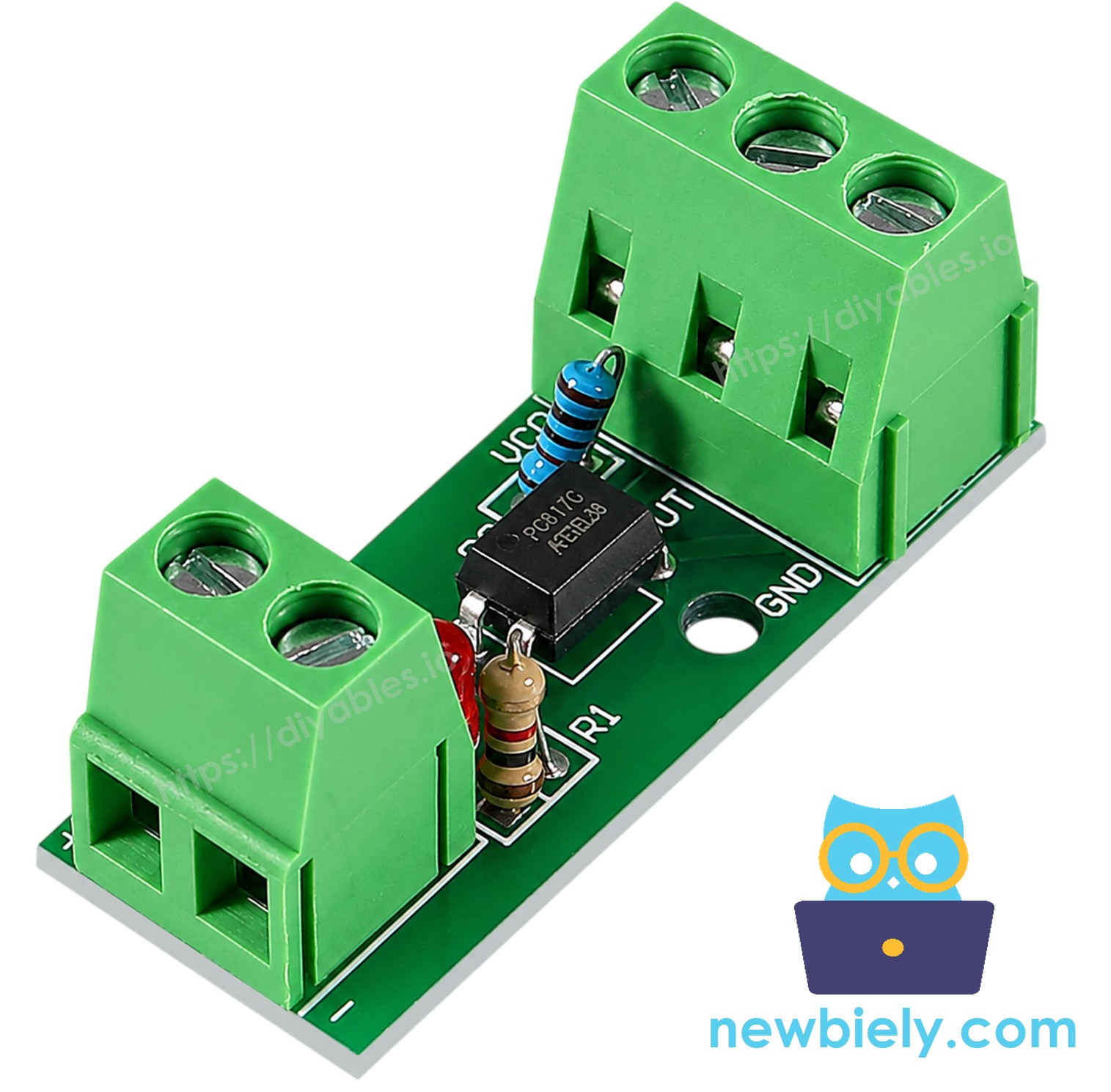
Its terminals are split the same way the chip is:
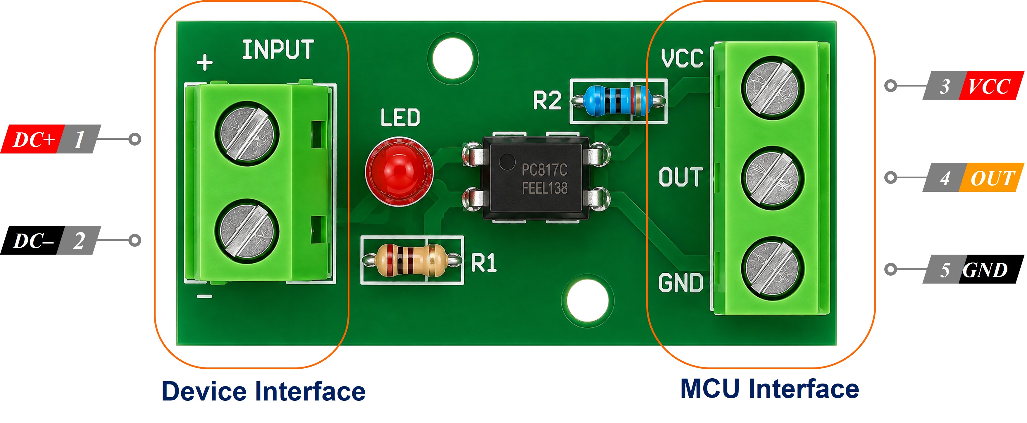
- Input side: a + (or IN+) screw terminal and a - (or IN-) screw terminal, for the external signal and the ground that signal belongs to.
- Output side: VCC, GND and OUT header pins (DO, or OUT1 to OUTn on multi-channel boards), which go to the Arduino.
Because the resistor is already fitted, you never calculate anything. But that resistor was sized for one input voltage before the board left the factory, and that is the decision you have to get right at the moment you order it.
Which PC817 Optocoupler Module Do I Need - 3-5V, 12V or 24V?
Start from the voltage that will appear across the input terminals, and let the table pick the board for you:
| Signal you want to watch | Module variant to order | Where that signal usually comes from |
|---|---|---|
| 24V DC | 24V optocoupler module | Lift and shutter limit lines, PLC transistor outputs, industrial panel lamps, barrier controllers |
| 12V DC | 12V optocoupler module | Boat and RV accessory circuits, alarm panels, automotive-style relays and solenoids |
| 5V DC | 3-5V optocoupler module | Another microcontroller, or a sensor board fed from its own 5V supply |
| 3.3V DC | 3-5V optocoupler module | A 3.3V board that does not share a ground with this one |
The bottom two rows surprise people, because nothing about 5 V or 3.3 V can hurt a pin. They are there because isolation is really about cutting the ground path, not about the size of the voltage: two boards fed from separate supplies, sitting at either end of a lift shaft, or sharing a cabinet with a motor drive, will never quite agree on where 0 V is. A 5V or 3.3V signal crossing that kind of gap is worth taking through a 3-5V module.
WARNING
Order the variant, do not improvise it. Put a 12V module on a 24V line and roughly double the intended current runs through its internal LED, which will damage it. Put a 24V module on a 12V line and the LED is underdriven, so the output switches late, switches unreliably, or never switches at all. Choosing the variant is the module owner's version of sizing the resistor, and it is the one purchase decision on this page that really matters.
If you already know you will meet more than one voltage on the same machine, buy one module of each variant rather than hoping a single board stretches across them. They cost very little, and a spare module in the drawer is cheaper than a burnt one on the panel.
If You Would Rather Build It from the Bare PC817 Chip
A module is only a PC817 with its resistor pre-soldered, so nothing stops you from doing that part yourself on a breadboard. Pin 1 carries a dot or a notch, and the rest count round:
- Pin 1 - Anode (A): LED anode, the positive side of the input, reached through the series resistor.
- Pin 2 - Cathode (K): LED cathode, wired to the ground of the external circuit and never to the Arduino GND.
- Pin 3 - Emitter (E): phototransistor emitter, wired to the Arduino GND.
- Pin 4 - Collector (C): phototransistor collector, wired to the Arduino digital input pin.
Size the resistor with R = (Vin - 1.2) / 0.01 for 10 mA through the LED, then round up: 220 ohm at 3.3V, 390 ohm at 5V, 1 kohm at 12V, 2.2 kohm at 24V (use 1/2 W there). Change the input voltage and the resistor must change too - a 1 kohm left on a 24V line passes about 22.8 mA, past the LED's 20 mA ceiling.
How It Works
The output transistor of the PC817 can only pull the Arduino pin down to GND; it cannot push it up. Something has to hold the pin HIGH the rest of the time, and the internal pull-up of the Arduino does that job for free. With the pull-up switched on:
- External 12V/24V signal PRESENT ⇒ LED on ⇒ transistor conducts ⇒ the pin reads LOW.
- External 12V/24V signal ABSENT ⇒ LED off ⇒ transistor off ⇒ the pin reads HIGH.
So on the bare chip the reading is inverted. A live line gives you a 0, not a 1. Forget this and your code will report the machine as running exactly when it is stopped. The same inversion appears wherever a pull-up is used, for instance in the Arduino MicroPython Button tutorial and the Arduino MicroPython Limit Switch tutorial.
WARNING
The ground of the 12V/24V circuit must NOT be joined to the Arduino GND. Those two grounds staying apart is the whole reason the PC817 is in the circuit. Tie them together and the chip keeps switching perfectly, so nothing looks wrong - but the isolation is gone, and a spike on the 24V side now has a direct path into the board.
If, instead of reading a high-voltage signal, you need to switch one, that is the opposite job and belongs to a relay.
Is Your Optocoupler Module Active High or Active Low?
The inversion above is settled physics for the bare chip. On a module it is not a promise, because some manufacturers add a stage on the board that turns the output back the right way up, so it follows the input instead. Both kinds are on sale, they look alike, and the listing rarely tells you which one is on its way to you. So do not assume - spend a minute in the Thonny Shell and find out:
- Wire the module as shown below and run the first script on this page in Thonny.
- Leave the input screw terminals dead. Whatever the Shell prints in those first seconds is your module's idle wording.
- Now energise the input terminals with the real signal, and keep watching the Shell.
- Whatever the Shell prints while the signal is present is your module's active level. If that wording matches the true state of the line, you are finished.
- Cross-check against the module's own input LED, which lights whenever the input side is energised. LED lit and Shell saying LIVE means the script agrees with the hardware; LED lit and Shell still saying idle means your module is active-HIGH.
Correcting an active-HIGH module is one word. Both scripts on this page carry the same constant near the top:
Set it to False, save the file again with Ctrl+S, press Run, and every reading in the rest of the script turns round with it. Nothing else in the code is touched, and the wiring stays exactly as it is.
Wiring Diagram
Wiring the PC817 Optocoupler Isolation Module
- External signal wire → the + (IN+) screw terminal.
- Ground of that same external circuit → the - (IN-) screw terminal.
- Module VCC → Arduino 3.3V.
- Module GND → Arduino GND.
- Module OUT → Arduino pin D2.
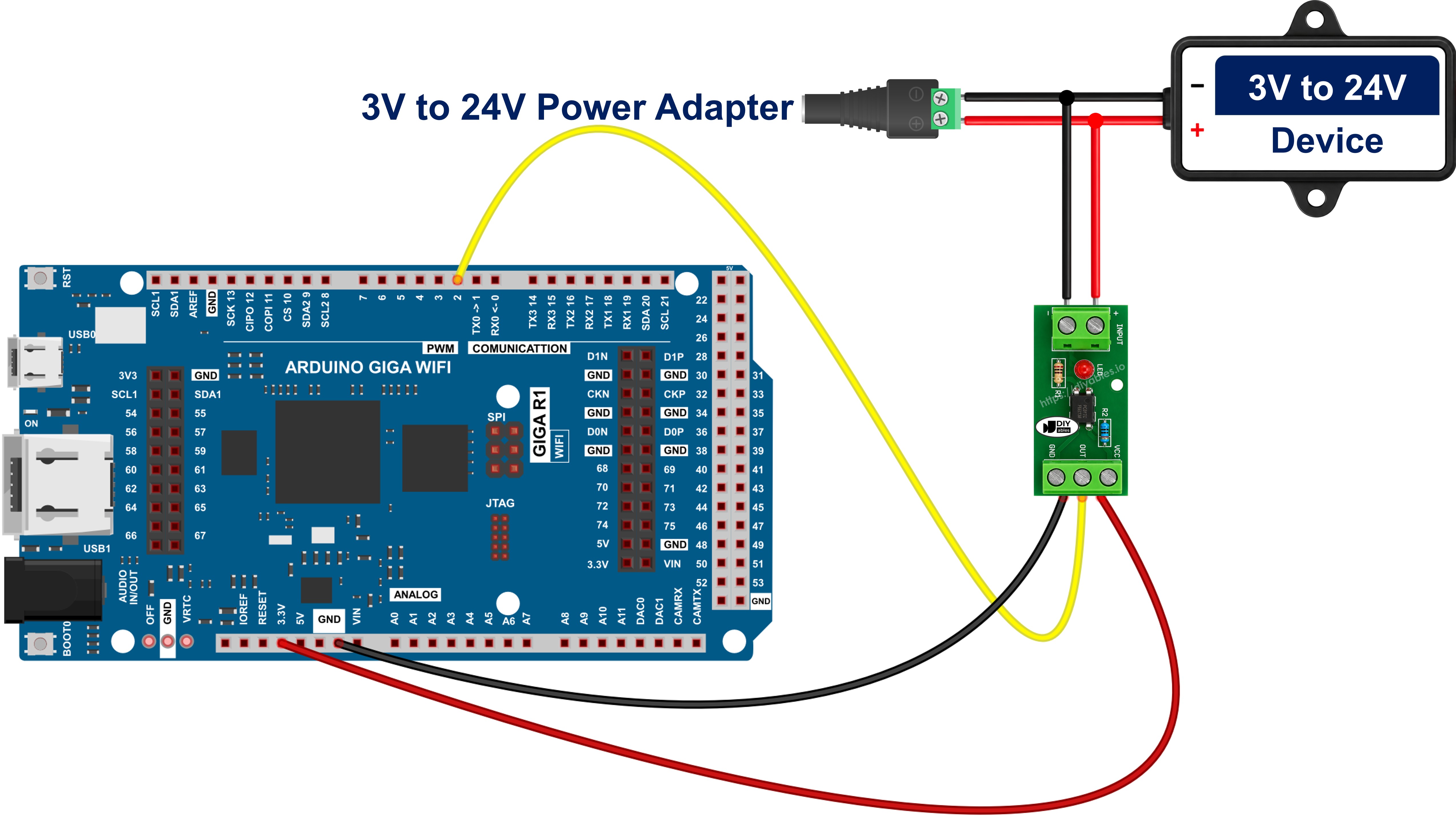
This image is created using Fritzing. Click to enlarge image
No resistor goes anywhere in this wiring. The one on the module is already the right size for the variant you ordered, and adding another in the input leg only starves the LED.
※ NOTE THAT:
The Arduino Giga R1 WiFi runs on 3.3V logic, so power the module from the 3.3V pin rather than the 5V pin. The pull-up on the Arduino side then holds the input pin at 3.3V, which is what the board expects.
Wiring the Bare PC817 Chip
If you took the breadboard route instead, the input side of the chip faces the equipment and the output side faces the Arduino, with no wire crossing between them:
- 12V/24V signal wire → series resistor (1 kohm for 12V, 2.2 kohm for 24V) → PC817 pin 1 (anode).
- PC817 pin 2 (cathode) → ground of the 12V/24V circuit only.
- PC817 pin 3 (emitter) → Arduino GND.
- PC817 pin 4 (collector) → Arduino pin D2.
Give the two halves of the breadboard some distance. Keeping the 12V/24V jumpers at one end and the Arduino jumpers at the other makes it obvious at a glance that no ground wire has sneaked across.
Reading a Device On or Off by Tapping the Module in Parallel
Both diagrams above assume a spare signal wire is waiting for you. Out on a real machine there rarely is one. What you have instead is a device already doing its job, and a question about it: has the goods lift reached its landing, has the shutter run down to its bottom limit, is the barrier boom actually parked? The 24V position lamp that the limit switch feeds on the controller panel answers all three - so that lamp is what the optocoupler listens to, by sitting across it, in parallel, the way you would hang a voltmeter on it.
Two new wires are all it takes, and both land on terminals that already exist:
- Switched positive terminal of the lamp → the + (IN+) screw terminal of a 24V module.
- Return (0 V) terminal of the same lamp → the - (IN-) screw terminal of the same module.
Nothing is cut, unlanded or diverted, and the lift's own circuit never knows you were there. On a bare-chip build the same tap goes to pin 1 through a 2.2 kohm resistor and to pin 2 directly; on the module that resistor is already aboard, so the tap really is just two wires.
WARNING
The tap goes across the device, never in line with it. Put the optocoupler input in series and the whole working current of the lamp - or worse, of a valve or a motor - is forced through an input LED rated for 20 mA, and the part dies the instant the limit switch closes.
The tap draws only the few milliamps the input stage was built for. A panel lamp of that kind already pulls somewhere near 120 mA, and a brake solenoid or a hoist contactor far more, so nothing downstream notices the extra load and the machine behaves precisely as it did before. It is a read-only measurement bolted onto a working circuit.
Three details decide whether it works the first time you power up:
- Get the polarity right. Behind the two input terminals there is an LED, and an LED passes current one way only. Land the tap the wrong way round and nothing breaks - the channel simply never comes on and the status LED never lights, which is a frustrating fault to chase. Identify the positive side of the pair before you strip either wire.
- Clamp anything inductive. If the point you are tapping is a coil rather than a lamp - the shutter's brake solenoid, a hoist relay, a hydraulic valve on a barrier - it fires a heavy reverse spike back down its own wires every time it releases, and the PC817 LED behind those terminals survives only 6 V in reverse. Put an ordinary diode in reverse-parallel straight across the input terminals, cathode on + and anode on -. While the tap is live it is reverse-biased and idle; when the spike arrives it conducts and holds the reverse voltage to well under a volt. A 1N4148 covers a light tap, a 1N4007 a heavier one.
- Drain a leaky output. Transistor and triac outputs on a PLC, and plenty of LED-lamp drivers, pass a trickle of current even while they are switched off. That trickle is often enough to half-light the input LED, and Thonny then insists the lift is at its limit while it is sitting mid-shaft. The tell-tale is a reading that never falls back to idle. Fit a bleeder resistor of 4.7 kohm to 10 kohm across the input terminals and the leakage takes that path instead of the LED.
Because the tap follows the device's own supply rather than a command, the reading tracks reality. It catches the shutter being driven down by the key switch on the wall, or by an interlock upstream, and it just as clearly shows a limit line that never came up when the platform should have arrived. That is the raw material for run-hour totals on the hoist, an idle-time log for the shutter, and a "did it actually start?" alert when the barrier is told to move and the position line stays dead.
※ NOTE THAT:
Be honest about what the tap proves: the device is energised, not that it is doing anything useful. A seized hoist motor or a burnt-out heater still takes current and will still read as ON. Use the optocoupler to confirm power, and something else - a limit switch, a current sensor, a timer - to confirm work.
※ NOTE THAT:
This is a DC-only trick. The PC817 input is a single LED and answers to one polarity, so it is the wrong part for sensing an AC line; that job wants an optocoupler whose input stage carries two LEDs back to back.
How To Program For PC817 Optocoupler
- Set up the Arduino pin as an input and switch the internal pull-up on. The pull-up is what holds the pin HIGH while the optocoupler is idle.
- Keep the polarity of your module in one constant, so that a module wired the other way round costs you a single edit.
- Read the raw pin value. On an active-LOW module a live input gives 0 and an idle one gives 1.
- Turn that raw value into a plain yes-or-no once, right where you take it, so the rest of the program stays readable.
Arduino MicroPython Code - Reading the Isolated Input
Detailed Instructions
Here's instructions on how to run the above MicroPython code on Arduino with Thonny IDE:
- Pick the module variant that matches the line you are about to watch - the 24V module for a 24V limit line - and wire it as shown in the diagram above.
- Double-check that the ground of the 12V/24V circuit goes nowhere near the Arduino GND before you power anything up.
- Make sure Thonny IDE is installed on your computer.
- Make sure MicroPython firmware is installed on your Arduino board.
- If you are new to Arduino with MicroPython, see the Getting Started with Arduino and MicroPython.
- Connect the Arduino board to your computer with a USB cable.
- Open Thonny IDE and go to Tools Options.
- Under the Interpreter tab, select MicroPython (generic) from the dropdown menu.
- Select the COM port corresponding to your Arduino board (e.g., COM33 on Windows or /dev/ttyACM0 on Linux).
- Copy the provided Arduino MicroPython code and paste it into Thonny's editor.
- Save the MicroPython code to your Arduino by:
- Clicking the Save button or pressing Ctrl+S.
- In the save dialog, choose MicroPython device and name the file main.py.
- Click the green Run button (or press F5) to execute the code.
- Energise the 24V line, leave it on for a few seconds, then switch it off again while watching the Shell at the bottom of Thonny.
This first run doubles as the polarity check described earlier. If the Shell says LIVE while the module's status LED is dark, or idle while it is lit, your module is active-HIGH: set MODULE_ACTIVE_LOW to False and run it again.
Nothing in the code changes if you move the same script to a 12V line - only the module does. Swap the 24V variant for the 12V one and the script keeps working exactly as it is.
Code Explanation
You can see the explanation in the comments part of the Arduino MicroPython code that was given before.
Arduino MicroPython Code - Detecting the Moment the Signal Appears
Printing the same line twice a second is handy for a first test, but for a shutter limit or a marine accessory circuit you usually only want to hear about a change. This second script remembers the last reading and speaks up only when the isolated input flips. It carries the same MODULE_ACTIVE_LOW constant, so both scripts read your module the same way round.
Detailed Instructions
- Copy the code above and paste it into Thonny IDE's editor.
- Save the script to your Arduino as main.py.
- Click the green Run button (or press F5) to run the script.
- Switch the external 24V line on and off a couple of times.
- Check out the message in the Shell at the bottom of Thonny.
※ NOTE THAT:
The PC817 itself does not bounce, but the mechanical switch or contactor feeding it very often does, so a single flick of a machine's limit switch can print several transitions in a row. If that happens, ignore any change that arrives less than about 50 ms after the previous one - the same debouncing idea used in the Arduino MicroPython Button Debounce tutorial.