Arduino Giga R1 WiFi DC Motor Shield

The Arduino Giga R1 WiFi packs a dual-core STM32H747 processor, built-in Wi-Fi and Bluetooth, and plenty of RAM - yet it still sports Uno-compatible headers. That makes it a perfect match for the Motor Shield Rev3 when your motor project also needs wireless connectivity or heavy computation.

By the end of this tutorial you will know how to:

Arduino Giga R1 WiFi DC Motor Shield

Hardware Preparation

1×Arduino Giga R1 WiFi
1×USB Cable Type-A to Type-C (for USB-A PC)
1×USB Cable Type-C to Type-C (for USB-C PC)
1×Motor Shield for Arduino
1×DC Motor (e.g, 5V)
1×Power source (e.g., 5V power Adapter)
1×DC Power Jack
1×Recommended: Screw Terminal Block Shield for Arduino Uno/Mega/Giga
1×Recommended: Sensors/Servo Expansion Shield for Arduino Uno/Mega/Giga
1×Recommended: Breadboard Shield for Arduino Mega/Giga
1×Recommended: Enclosure for Arduino Giga
1×Recommended: Power Splitter for Arduino Giga

Or you can buy the following kits:

1×DIYables Sensor Kit (18 sensors/displays)
Disclosure: Some of the links provided in this section are Amazon affiliate links. We may receive a commission for any purchases made through these links at no additional cost to you.
Additionally, some of these links are for products from our own brand, DIYables .

The Motor Shield Rev3 Explained

Beneath the shield's screw terminals lives an L298P dual full-bridge driver IC. It handles the heavy lifting of switching motor polarity and modulating power - your Arduino sketch just toggles a handful of digital and analog pins.

Each of the two independent motor channels offers:

  • A direction digital output - write HIGH or LOW to choose the rotation sense.
  • A PWM output - vary the duty cycle between 0 (halted) and 255 (maximum torque).
  • A brake digital output - pull HIGH to lock the motor instantly, or set LOW to let it coast.
  • A current-sensing analog input - reads a voltage that scales with the current flowing through the motor.

The Giga R1 WiFi's Uno-compatible headers place these signals on the standard pins:

Function Channel A Channel B
Direction D12 D13
PWM (Speed) D3 D11
Brake D9 D8
Current Sensing A0 A1

About External Power

The L298P can deliver up to 2 A per channel - far beyond what USB provides. Attach a 6-12 V battery pack (or bench supply) to the power screw terminals on the shield. The Giga R1 WiFi itself draws power from USB Type-C independently.
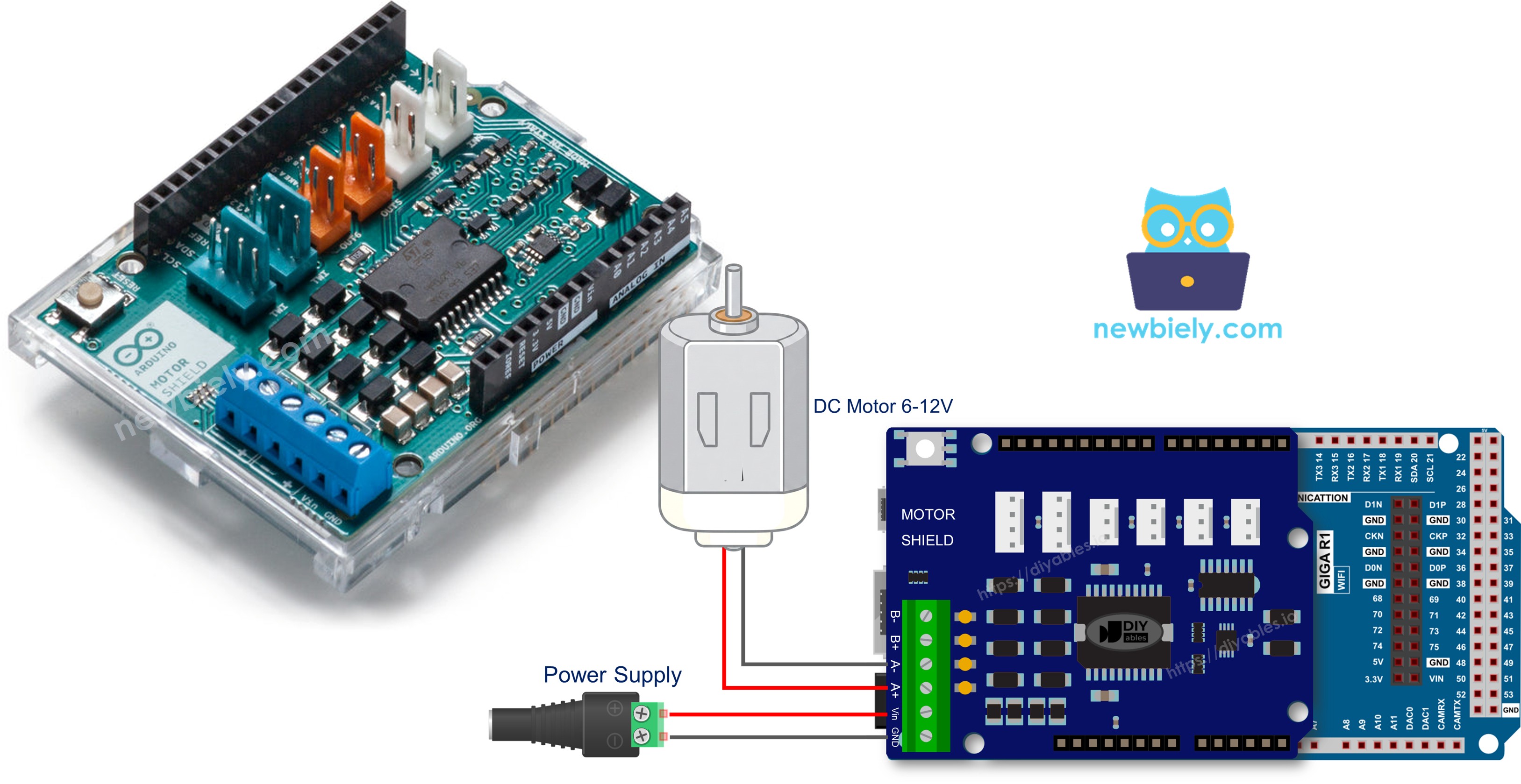
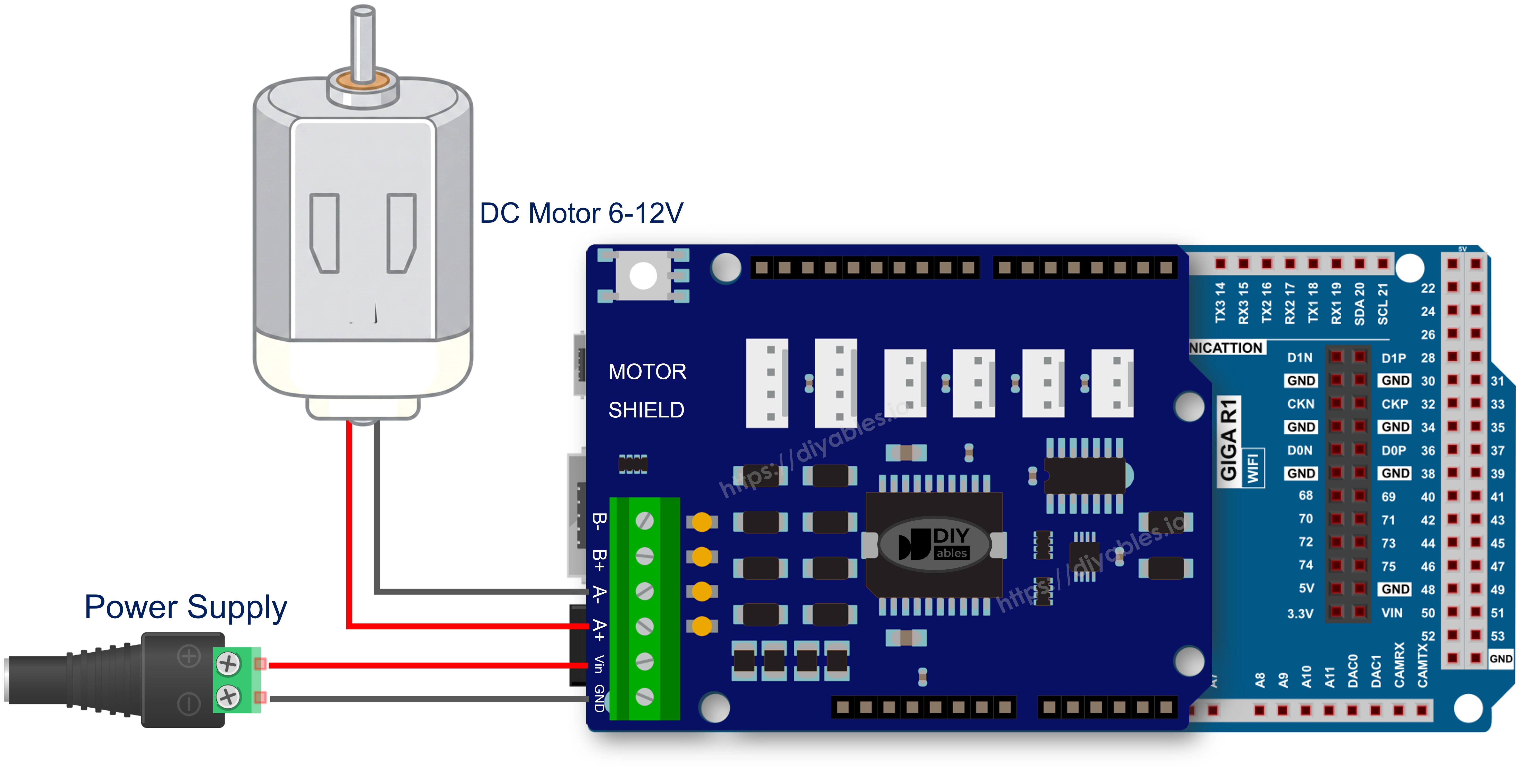
Wiring Diagram

Carefully line up the Motor Shield Rev3 with the Giga R1 WiFi headers and press it into place. No soldering, no breadboard.

Run the motor leads to the Channel A screw terminals. Connect your external battery to the power terminals, observing polarity.

The wiring diagram between Arduino Giga R1 WiFi DC Motor Shield

This image is created using Fritzing. Click to enlarge image

Setting Up the Library

  1. Connect the Giga R1 WiFi to your computer through the USB Type-C port.
  2. Launch the Arduino IDE, then select Arduino Giga R1 WiFi from the board menu and pick the appropriate port.
  3. Open the Libraries panel.
  4. Enter "DIYables_DC_Motor" in the search field. The library from DIYables should appear.
  5. Click Install.
Arduino DC Motor Shield library

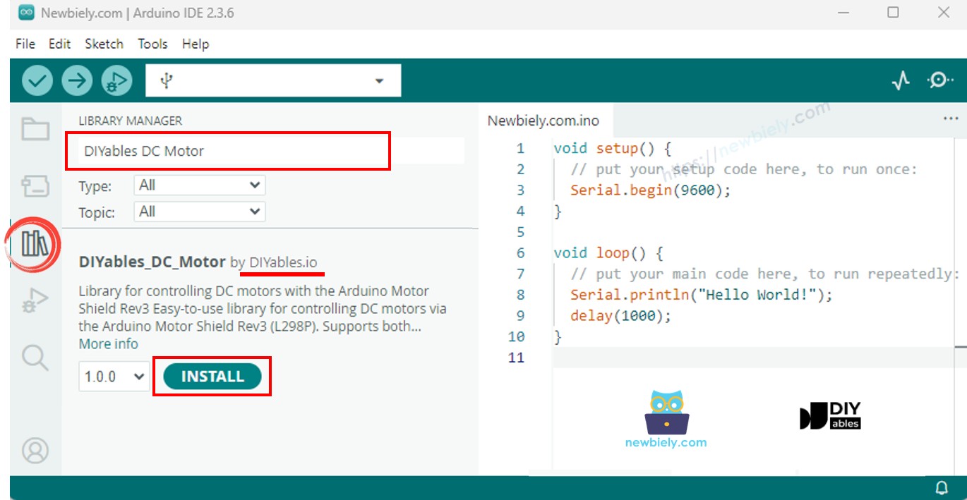
Everything is included in the library package - there are no extra dependencies to install.

Program Template

Here is the simplest program that drives a motor:

#include <DIYables_DC_Motor.h> DIYables_DC_Motor motor(MOTOR_CH_A); void setup() { motor.begin(); } void loop() { motor.run(MOTOR_FORWARD, 100); delay(2000); motor.brake(); delay(1000); }

Three calls are all you need: begin() prepares the hardware, run() starts the motor, and brake() stops it. The motor continues spinning at the last requested speed until you issue a new command.

Driving a Motor on Channel A

Toggle a single motor between forward and reverse rotation, stopping in between.

/* * This Arduino Giga R1 WiFi code was developed by newbiely.com * * This Arduino Giga R1 WiFi code is made available for public use without any restriction * * For comprehensive instructions and wiring diagrams, please visit: * https://newbiely.com/tutorials/arduino-giga/arduino-giga-r1-wifi-dc-motor-shield */ /* * DIYables_DC_Motor - ChannelA Example * * This example demonstrates how to control a DC motor connected to * Channel A of the Arduino Motor Shield Rev3. The motor alternates * direction every 2 seconds with braking in between. * * Channel A pins: D12 (Direction), D3 (PWM), D9 (Brake), A0 (Current) * * Tutorial: https://diyables.io/motor-shield * * TESTED HARDWARE: * - Arduino Uno R3 * - Arduino Uno R4 WiFi * - Arduino Uno R4 Minima * - Arduino Mega * - Arduino Due * - Arduino Giga * - DIYables STEM V3: https://diyables.io/stem-v3 * - DIYables STEM V4 IoT: https://diyables.io/stem-v4-iot * - DIYables STEM V4B IoT: https://diyables.io/stem-v4b-iot * - DIYables STEM V4B Edu: https://diyables.io/stem-v4-edu * - DIYables MEGA2560 R3: https://diyables.io/atmega2560-board * - It is expected to work with other boards */ #include <DIYables_DC_Motor.h> DIYables_DC_Motor motor(MOTOR_CH_A); bool directionState = false; void setup() { Serial.begin(9600); motor.begin(); Serial.println("Motor Shield - Channel A"); } void loop() { // Toggle direction each cycle directionState = !directionState; int direction = directionState ? MOTOR_FORWARD : MOTOR_BACKWARD; // Run motor with speed 30 (out of 255) motor.run(direction, 30); Serial.print("Running "); Serial.println(directionState ? "FORWARD" : "BACKWARD"); delay(2000); // Brake the motor motor.brake(); Serial.println("Braking"); delay(2000); }

Getting Started

  • Seat the shield onto the Giga R1 WiFi and connect the motor to Channel A.
  • Attach the battery pack.
  • Plug in the USB Type-C cable.
  • In Arduino IDE, confirm the board and port settings, paste the code, and tap Upload.
  • Open the Serial Monitor to track direction changes.

The motor spins at speed 30 for two seconds, brakes for two seconds, reverses, and loops.

Motor Control Methods

Method Description Example Call
run(dir, speed) Sets direction and speed; releases brake automatically motor.run(MOTOR_FORWARD, 100)
setSpeed(speed) Updates PWM output (0-255) motor.setSpeed(180)
setDirection(dir) Switches rotation sense motor.setDirection(MOTOR_BACKWARD)
brake() Locks shaft and zeroes PWM motor.brake()
release() Frees the brake without changing speed motor.release()
readCurrent() Returns raw ADC from the sensing pin motor.readCurrent()

Driving a Motor on Channel B

Same experiment, wired to the second channel.

/* * This Arduino Giga R1 WiFi code was developed by newbiely.com * * This Arduino Giga R1 WiFi code is made available for public use without any restriction * * For comprehensive instructions and wiring diagrams, please visit: * https://newbiely.com/tutorials/arduino-giga/arduino-giga-r1-wifi-dc-motor-shield */ /* * DIYables_DC_Motor - ChannelB Example * * This example demonstrates how to control a DC motor connected to * Channel B of the Arduino Motor Shield Rev3. The motor alternates * direction every 2 seconds with braking in between. * * Channel B pins: D13 (Direction), D11 (PWM), D8 (Brake), A1 (Current) * * Tutorial: https://diyables.io/motor-shield * * TESTED HARDWARE: * - Arduino Uno R3 * - Arduino Uno R4 WiFi * - Arduino Uno R4 Minima * - Arduino Mega * - Arduino Due * - Arduino Giga * - DIYables STEM V3: https://diyables.io/stem-v3 * - DIYables STEM V4 IoT: https://diyables.io/stem-v4-iot * - DIYables STEM V4B IoT: https://diyables.io/stem-v4b-iot * - DIYables STEM V4B Edu: https://diyables.io/stem-v4-edu * - DIYables MEGA2560 R3: https://diyables.io/atmega2560-board * - It is expected to work with other boards */ #include <DIYables_DC_Motor.h> DIYables_DC_Motor motor(MOTOR_CH_B); bool directionState = false; void setup() { Serial.begin(9600); motor.begin(); Serial.println("Motor Shield - Channel B"); } void loop() { // Toggle direction each cycle directionState = !directionState; int direction = directionState ? MOTOR_FORWARD : MOTOR_BACKWARD; // Run motor with speed 30 (out of 255) motor.run(direction, 30); Serial.print("Running "); Serial.println(directionState ? "FORWARD" : "BACKWARD"); delay(2000); // Brake the motor motor.brake(); Serial.println("Braking"); delay(2000); }

Getting Started

  • Reconnect the motor to the Channel B terminals.
  • Upload the sketch and open the Serial Monitor.

No code logic changes - the constructor constant handles the pin swap.

Dual-Motor Control

Orchestrate two motors through synchronized and opposing motion patterns.

/* * This Arduino Giga R1 WiFi code was developed by newbiely.com * * This Arduino Giga R1 WiFi code is made available for public use without any restriction * * For comprehensive instructions and wiring diagrams, please visit: * https://newbiely.com/tutorials/arduino-giga/arduino-giga-r1-wifi-dc-motor-shield */ /* * DIYables_DC_Motor - BothChannels Example * * This example demonstrates how to control two DC motors simultaneously, * one on Channel A and one on Channel B of the Arduino Motor Shield Rev3. * * Channel A pins: D12 (Direction), D3 (PWM), D9 (Brake), A0 (Current) * Channel B pins: D13 (Direction), D11 (PWM), D8 (Brake), A1 (Current) * * Tutorial: https://diyables.io/motor-shield * * TESTED HARDWARE: * - Arduino Uno R3 * - Arduino Uno R4 WiFi * - Arduino Uno R4 Minima * - Arduino Mega * - Arduino Due * - Arduino Giga * - DIYables STEM V3: https://diyables.io/stem-v3 * - DIYables STEM V4 IoT: https://diyables.io/stem-v4-iot * - DIYables STEM V4B IoT: https://diyables.io/stem-v4b-iot * - DIYables STEM V4B Edu: https://diyables.io/stem-v4-edu * - DIYables MEGA2560 R3: https://diyables.io/atmega2560-board * - It is expected to work with other boards */ #include <DIYables_DC_Motor.h> DIYables_DC_Motor motorA(MOTOR_CH_A); DIYables_DC_Motor motorB(MOTOR_CH_B); void setup() { Serial.begin(9600); motorA.begin(); motorB.begin(); Serial.println("Motor Shield - Both Channels"); } void loop() { // Both motors forward motorA.run(MOTOR_FORWARD, 100); motorB.run(MOTOR_FORWARD, 100); Serial.println("Both FORWARD"); delay(2000); // Brake both motors motorA.brake(); motorB.brake(); Serial.println("Both BRAKING"); delay(1000); // Both motors backward motorA.run(MOTOR_BACKWARD, 100); motorB.run(MOTOR_BACKWARD, 100); Serial.println("Both BACKWARD"); delay(2000); // Brake both motors motorA.brake(); motorB.brake(); Serial.println("Both BRAKING"); delay(1000); // Motors in opposite directions motorA.run(MOTOR_FORWARD, 150); motorB.run(MOTOR_BACKWARD, 150); Serial.println("A FORWARD, B BACKWARD"); delay(2000); // Brake both motors motorA.brake(); motorB.brake(); Serial.println("Both BRAKING"); delay(1000); }

Getting Started

  • Wire one motor to Channel A and another to Channel B.
  • Upload and monitor via Serial.

The sketch demonstrates three phases: both forward, both backward, and opposing directions, each separated by a braking interval.

Measuring Motor Current

Continuously read the current drawn by a running motor.

/* * This Arduino Giga R1 WiFi code was developed by newbiely.com * * This Arduino Giga R1 WiFi code is made available for public use without any restriction * * For comprehensive instructions and wiring diagrams, please visit: * https://newbiely.com/tutorials/arduino-giga/arduino-giga-r1-wifi-dc-motor-shield */ /* * DIYables_DC_Motor - CurrentSensing Example * * This example demonstrates how to read the current drawn by a DC motor * connected to Channel A of the Arduino Motor Shield Rev3. * * The Motor Shield Rev3 provides current sensing via analog pins: * Channel A: A0 * Channel B: A1 * * Tutorial: https://diyables.io/motor-shield * * TESTED HARDWARE: * - Arduino Uno R3 * - Arduino Uno R4 WiFi * - Arduino Uno R4 Minima * - Arduino Mega * - Arduino Due * - Arduino Giga * - DIYables STEM V3: https://diyables.io/stem-v3 * - DIYables STEM V4 IoT: https://diyables.io/stem-v4-iot * - DIYables STEM V4B IoT: https://diyables.io/stem-v4b-iot * - DIYables STEM V4B Edu: https://diyables.io/stem-v4-edu * - DIYables MEGA2560 R3: https://diyables.io/atmega2560-board * - It is expected to work with other boards */ #include <DIYables_DC_Motor.h> DIYables_DC_Motor motor(MOTOR_CH_A); void setup() { Serial.begin(9600); motor.begin(); Serial.println("Motor Shield - Current Sensing"); } void loop() { // Run motor forward motor.run(MOTOR_FORWARD, 100); // Read and print current sensing value int current = motor.readCurrent(); Serial.print("Current sensing (raw ADC): "); Serial.println(current); delay(500); }

Getting Started

  • Attach a motor to Channel A.
  • Upload and open the Serial Monitor.
  • Watch the raw ADC value update every 500 ms.

Interpreting the Reading

The Giga R1 WiFi's default ADC resolution produces values in the 0-1023 range. Apply the motor shield's documented voltage-to-current ratio to convert the reading into milliamps.

Using Custom Pins

When your hardware layout differs from the standard shield - perhaps you are using a breakout board or a custom PCB - specify every pin explicitly.

/* * This Arduino Giga R1 WiFi code was developed by newbiely.com * * This Arduino Giga R1 WiFi code is made available for public use without any restriction * * For comprehensive instructions and wiring diagrams, please visit: * https://newbiely.com/tutorials/arduino-giga/arduino-giga-r1-wifi-dc-motor-shield */ /* * DIYables_DC_Motor - CustomPins Example * * This example demonstrates how to create a motor object with * custom pin assignments instead of using the predefined channels. * * Tutorial: https://diyables.io/motor-shield * * TESTED HARDWARE: * - Arduino Uno R3 * - Arduino Uno R4 WiFi * - Arduino Uno R4 Minima * - Arduino Mega * - Arduino Due * - Arduino Giga * - DIYables STEM V3: https://diyables.io/stem-v3 * - DIYables STEM V4 IoT: https://diyables.io/stem-v4-iot * - DIYables STEM V4B IoT: https://diyables.io/stem-v4b-iot * - DIYables STEM V4B Edu: https://diyables.io/stem-v4-edu * - DIYables MEGA2560 R3: https://diyables.io/atmega2560-board * - It is expected to work with other boards */ #include <DIYables_DC_Motor.h> // Custom pin assignment: direction=12, pwm=3, brake=9, currentSensing=A0 DIYables_DC_Motor motor(12, 3, 9, A0); bool directionState = false; void setup() { Serial.begin(9600); motor.begin(); Serial.println("Motor Shield - Custom Pins"); } void loop() { // Toggle direction each cycle directionState = !directionState; int direction = directionState ? MOTOR_FORWARD : MOTOR_BACKWARD; // Run motor motor.run(direction, 30); Serial.print("Running "); Serial.println(directionState ? "FORWARD" : "BACKWARD"); delay(2000); // Brake the motor motor.brake(); Serial.println("Braking"); delay(2000); }

Getting Started

  • Substitute your actual pin numbers into the constructor.
  • Upload and verify that the motor responds correctly.

What to Check When Things Go Wrong

  • Complete silence from the motor - Verify external power polarity and voltage. Confirm that motor leads are tight in the screw terminals. Ensure the channel constant in code matches the physical connection.
  • Motor vibrates but does not turn - The speed value is probably too low. Bump it up to at least 50-80.
  • Unexpected direction - Either reverse the two motor wires at the terminal, or swap MOTOR_FORWARD and MOTOR_BACKWARD in your sketch.
  • readCurrent() returns -1 - You created the motor with the 3-pin constructor, which excludes current sensing. Switch to the channel constructor or the 4-pin variant.
  • Thermal shutdown - The motor may be stalled or overloaded. Keep each channel under 2 A continuous.

Platform Support

The library is built on Arduino's standard API surface - pinMode, digitalWrite, analogWrite, analogRead - and carries the architectures=* flag, so it compiles on every Arduino-supported platform.

Learn More

※ OUR MESSAGES

  • As freelancers, We are AVAILABLE for HIRE. See how to outsource your project to us
  • Please feel free to share the link of this tutorial. However, Please do not use our content on any other websites. We invested a lot of effort and time to create the content, please respect our work!