Arduino Giga R1 WiFi Door Sensor
This guide covers door sensor implementation with the Arduino Giga R1 WiFi for both state monitoring and event detection. The door sensor (also known as entry sensor, contact sensor, or window sensor) uses magnetic reed switch technology to detect open/closed states.
This tutorial covers reed switch operating principles, proper wiring with pull-up resistor configuration, and Arduino code for both state checking and event detection.
Hardware Preparation
Or you can buy the following kits:
| 1 | × | DIYables Sensor Kit (18 sensors/displays) |
Additionally, some of these links are for products from our own brand, DIYables .
Overview of Door Sensor
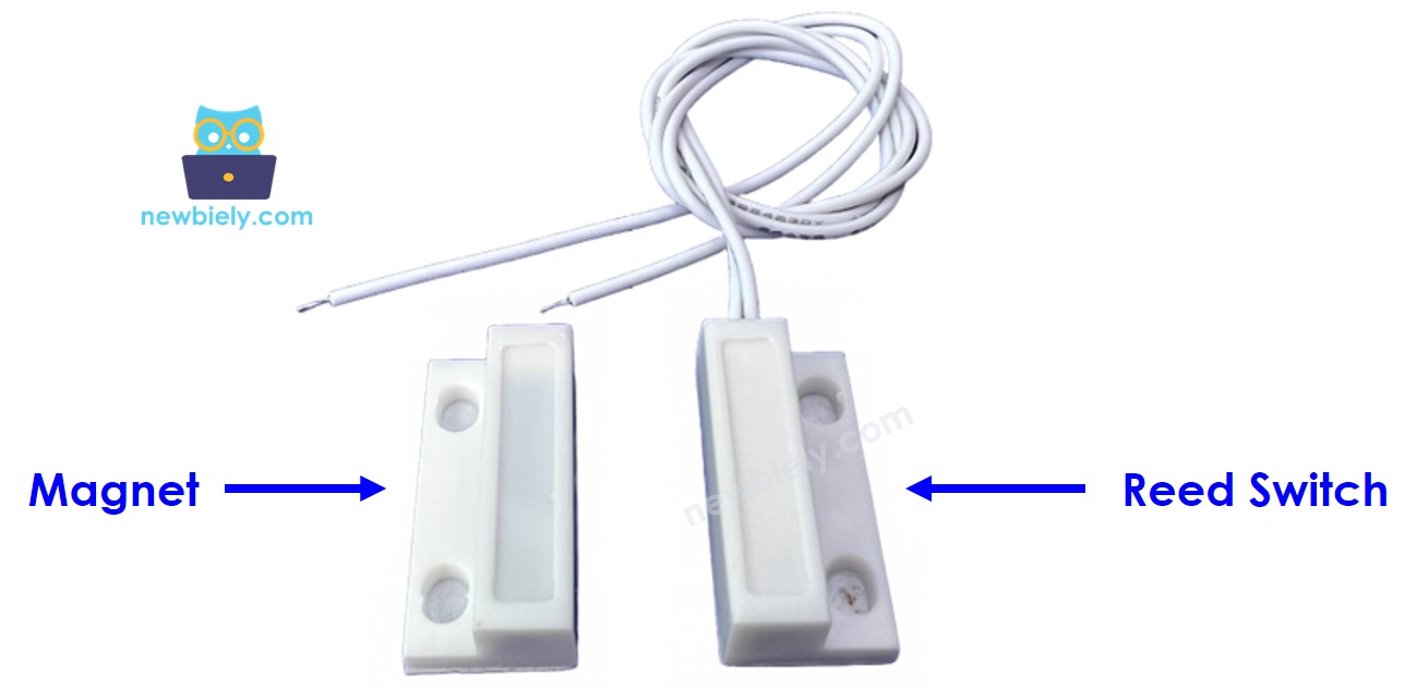
Door sensor is a magnetic proximity detection device with two components: a magnetically-actuated reed switch and a permanent magnet assembly. The reed switch operates at 5V logic levels with operating temperature from -40°C to +85°C and mechanical life exceeding 10^6 operations.
When the permanent magnet approaches within the sensor's effective range (typically 15-20mm), the magnetic field causes the normally-open reed contacts to close. When the magnet moves beyond this range, the contacts return to their open state. Sealed construction provides environmental protection, and magnetic actuation eliminates debouncing issues common with mechanical switches.
Pinout
The pinout configuration defines the electrical interface between the door sensor's reed switch and the Arduino Giga R1 WiFi. Correct wiring is essential — an incorrect connection may damage the component or produce unreliable readings due to floating inputs or excessive current draw.
Door sensor includes two components:
- One reed switch with two pins
- One magnet
Reed Switch Pins: Two terminals providing normally-open contact closure. Pin designation is non-polarized — either pin can serve as input or output connection. Contact resistance when closed: <100mΩ. Open circuit resistance: >10^12Ω. Maximum switching voltage: 200V DC. Maximum switching current: 200mA continuous.
Connection Specifications: One reed switch terminal connects to Arduino Giga R1 WiFi digital input pin configured with internal pull-up resistor enabled. The second terminal connects to ground (GND) to provide reference potential. When the magnetic field actuates the reed switch, it creates a direct path from the digital input to ground, pulling the pin to LOW logic state.
Magnet Component: Permanent magnet assembly with effective actuation distance of 15-20mm depending on orientation and mounting configuration. No electrical connections required — purely passive magnetic field source for reed switch activation.
How It Works
The door sensor operates through magnetic field proximity detection using a reed switch mechanism. The magnet is attached to the door/window (moving part), and the reed switch is attached to the door frame (fixed part). The two components are in contact when the door is closed.
- When the magnet is close to the reed switch, the reed switch circuit is closed
- When the magnet is far from the reed switch, the reed switch circuit is open
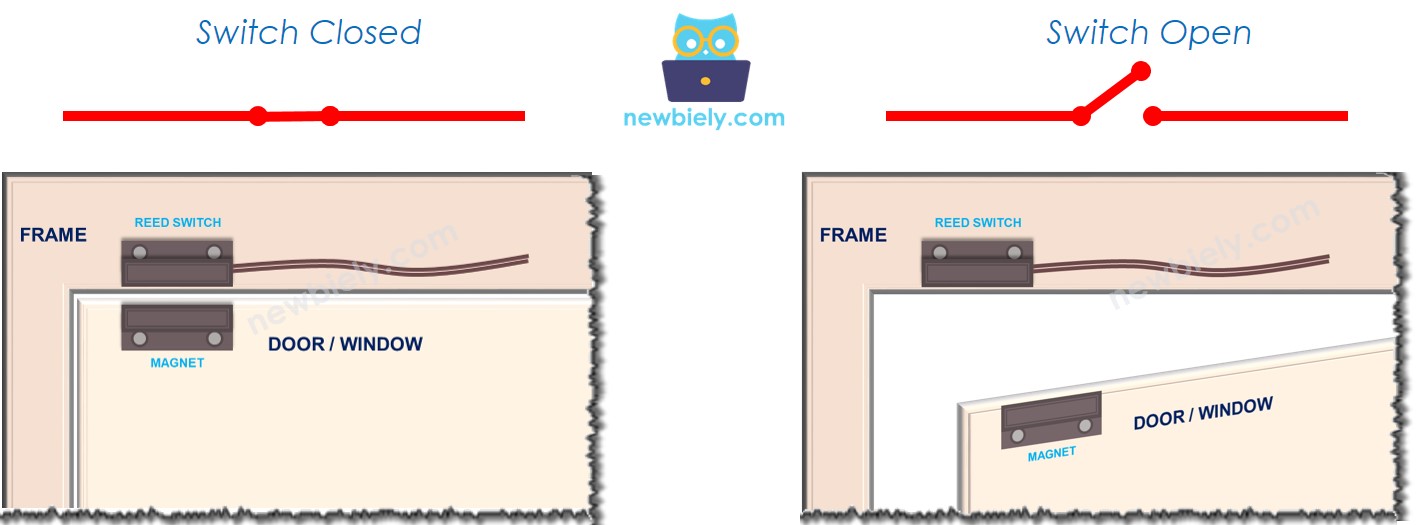
Critical Implementation Detail: The reed switch itself operates as a purely mechanical contact — it does NOT output digital logic levels (LOW or HIGH) on its pins. The switch exists only in closed or open states. The digital logic levels read by the Arduino Giga R1 WiFi depend entirely on the external circuit configuration, specifically the pull-up or pull-down resistor implementation.
※ NOTE THAT:
The reed switch itself does NOT output LOW or HIGH on its pins. It is just a closed or open state. Depending on how we connect its pins to Arduino, the value on the pin can be the LOW, HIGH, or floating value (unpredicted value). To avoid the floating value, we MUST use the pull-up or pull-down resistor on the Arduino pin
Recommended Configuration: Connect one reed switch terminal to GND, and the other terminal to an Arduino Giga R1 WiFi digital input pin configured with internal pull-up resistor (INPUT_PULLUP mode). This configuration ensures:
- When the magnet is close to the reed switch: contacts close, creating direct path to GND → Arduino input reads LOW (0V)
- When the magnet is far from the reed switch: contacts open, internal pull-up resistor pulls pin to VCC → Arduino input reads HIGH (3.3V)
State Detection Logic:
- To check the door state, monitor the Arduino digital input pin state:
- If the state is LOW, the door is closed (magnet near sensor)
- If the state is HIGH, the door is open (magnet far from sensor)
- To detect door-opening/door-closing events, implement edge detection on the Arduino input pin:
- State change from LOW to HIGH indicates door-opening event
- State change from HIGH to LOW indicates door-closing event
Timing Considerations: Reed switch actuation time is typically <1ms, well within the Arduino Giga R1 WiFi's polling capabilities. For critical timing applications, consider implementing interrupt-driven detection on the digital input pin to capture events with microsecond precision.
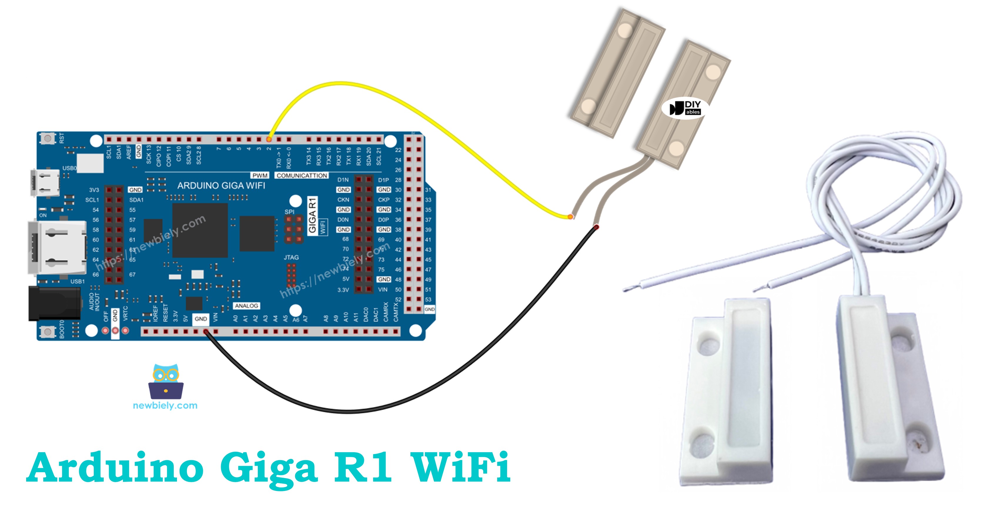
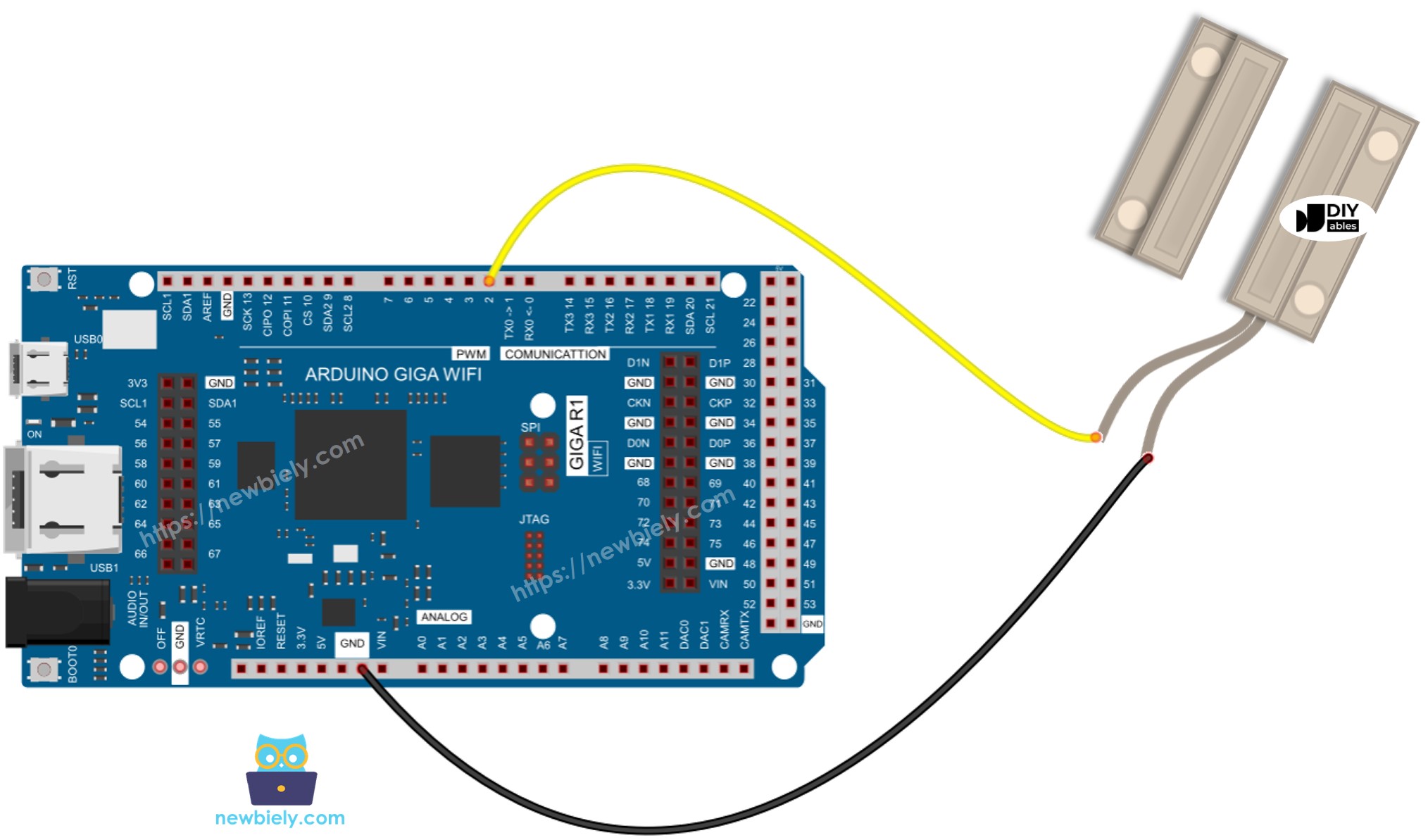
Wiring Diagram
This wiring configuration demonstrates the standard pull-up resistor implementation for reliable digital state detection. The Arduino Giga R1 WiFi's internal pull-up resistors eliminate the need for external components while providing stable logic levels.
Electrical Note: The diagram above shows the minimum viable connection for door sensor integration. For production or extended-use installations, consider adding a small capacitor (100nF) across the reed switch terminals to suppress electrical noise in high-EMI environments, and ensure proper mechanical mounting to maintain consistent magnetic gap distance.
This image is created using Fritzing. Click to enlarge image
| Reed Switch Pin 1 | Arduino Giga R1 WiFi Pin 2 (Digital Input) |
|---|---|
| Reed Switch Pin 2 | GND |
| Magnet | No electrical connection (mechanical mounting only) |
Power Supply Requirements: The door sensor draws no continuous current — power consumption occurs only during the brief moments when the Arduino samples the digital input state. Total system current draw is dominated by the Arduino's own consumption rather than the sensor itself.
How To Program For Door Sensor
The following implementation demonstrates digital input polling with pull-up resistor configuration. The code is structured to handle both continuous state monitoring and edge-triggered event detection. Key programming sections focus on proper pin initialization, reliable state reading, and debouncing considerations for mechanical switch applications.
The Arduino's digitalRead() function provides the primary interface for door sensor state acquisition. The INPUT_PULLUP mode automatically enables the internal pull-up resistor, eliminating external component requirements while ensuring stable logic levels. This configuration is particularly effective with the Arduino Giga R1 WiFi's robust GPIO architecture.
Pin Configuration Process:
- Initialize: Configure the Arduino pin to digital input mode with internal pull-up resistor enabled using pinMode() function. For example, pin 2:
- Read State: Poll the current door sensor state using digitalRead() function to obtain the logic level:
Implementation Strategy: The polling approach works effectively for most door sensor applications. For systems requiring immediate event response or minimal power consumption, consider implementing external interrupt capability using attachInterrupt() with the door sensor pin configured for CHANGE, RISING, or FALLING edge detection.
Arduino Code - Check Door Open and Close State
This implementation demonstrates continuous door state monitoring with clear serial output indication. The code polls the door sensor at regular intervals and reports the current door position based on the magnetic proximity detection.
Detailed Instructions
For initial Arduino Giga R1 WiFi setup, refer to the Arduino Giga R1 WiFi Getting Started guide before proceeding.
- Connect Hardware: Wire the reed switch according to the diagram above, ensuring one terminal connects to digital pin 2 and the other to GND. Verify secure connections and proper magnet positioning relative to the reed switch.
- Open Arduino IDE: Launch the Arduino IDE and ensure the Arduino Giga R1 WiFi board package is selected. Verify the correct COM port is configured for your board connection.
- Upload Code: Copy the door state monitoring code and paste into a new Arduino sketch. Click the Upload button to compile and transfer the program to the Arduino Giga R1 WiFi. Monitor the compilation output for any errors.
- Test Operation: Open the Serial Monitor at 9600 baud rate. Move the magnet close to the reed switch to simulate door closing, then move it away to simulate door opening. The serial output should immediately reflect state changes.
- Verify Readings: Confirm the output logic matches the physical door position — "The door is closed" when magnet is near the sensor, "The door is open" when magnet is distant. If readings are inverted, check wiring connections.
- Observe Timing: Note the response time between physical magnet movement and serial output update. The 500ms delay in the loop provides readable output while demonstrating real-time state detection capability.
Technical Note: The INPUT_PULLUP configuration automatically handles pull-up resistor requirements, eliminating external components. For battery-powered applications, consider increasing the loop delay to reduce power consumption, or implement interrupt-driven detection to minimize active polling.
Arduino Code - Detect Door-opening and Door-closing Events
This advanced implementation focuses on edge detection to capture specific door-opening and door-closing events rather than continuous state polling. The code compares current readings with previous states to identify precise transition moments, enabling event-driven applications such as security logging or automation triggers.
Detailed Instructions
- Load Event Detection Code: Copy the event detection code into a new Arduino IDE sketch. This implementation includes state change detection logic that triggers only on door state transitions.
- Upload and Initialize: Upload the code to the Arduino Giga R1 WiFi and open the Serial Monitor at 9600 baud. The system will initialize and begin monitoring for state changes rather than continuous polling.
- Test Event Detection: Position the magnet away from the reed switch initially (door open state). Move the magnet close to trigger a door-closing event, then move it away to trigger a door-opening event. Each transition should generate exactly one event message.
- Verify Event Accuracy: Confirm that events trigger only on actual state transitions, not during continuous states. Rapid magnet movement should generate corresponding rapid event detection without false triggers.
- Monitor Response Time: Observe the timing between physical door movement and event detection. The system should respond within the loop delay period (typically <100ms for responsive event detection).
- Test Edge Cases: Verify proper event detection with slow door movement, quick multiple transitions, and varying magnet-to-sensor distances within the operational range.
Technical Note: Event detection provides more efficient operation for battery-powered systems and enables precise timestamp logging for security applications. The state comparison method eliminates redundant processing while maintaining reliable transition detection. For critical applications, consider implementing interrupt-based detection for sub-millisecond event timing accuracy.
Application Ideas
Security System Integration: Implement a comprehensive home security monitoring system using multiple door sensors connected to different Arduino Giga R1 WiFi digital inputs. The dual-core architecture enables simultaneous sensor monitoring while the WiFi capability provides real-time alerts to mobile devices or security monitoring services. Log entry/exit events with timestamps for forensic analysis.
Industrial Safety Monitoring: Deploy door sensors on equipment enclosures, safety barriers, and access panels in manufacturing environments. The Arduino Giga R1 WiFi's industrial-grade operating temperature range and robust GPIO design ensure reliable operation in harsh conditions. Integrate with industrial communication protocols for facility-wide safety system integration.
Smart Building Automation: Create an intelligent building management system that monitors conference room occupancy, storage access, and environmental control based on door positions. The Arduino Giga R1 WiFi's ample memory enables complex decision algorithms while WiFi connectivity allows integration with existing building management systems and IoT platforms.
Energy Management System: Monitor HVAC zone access to optimize heating and cooling based on actual room usage patterns. Door sensors provide occupancy inference data that, combined with the Arduino Giga R1 WiFi's computational capability, enables predictive energy management algorithms reducing operational costs.
Inventory and Asset Tracking: Implement cabinet and storage monitoring for valuable equipment or controlled substances. Event logging with WiFi-based data transmission enables real-time inventory management and unauthorized access detection. The Arduino Giga R1 WiFi's dual-core design supports simultaneous sensor monitoring and data communication tasks.
Laboratory and Cleanroom Monitoring: Deploy sensors on critical facility doors to ensure environmental isolation and contamination control. Integration with data logging systems provides compliance documentation while real-time monitoring enables immediate response to protocol violations.
Video Tutorial
The accompanying video demonstrates the complete hardware assembly process and live code execution for both door state monitoring and event detection implementations. It covers proper reed switch wiring techniques, magnet positioning considerations, and shows the expected serial monitor output during various door operation scenarios including normal opening/closing cycles and rapid transition testing.
Challenge Yourself
Challenge: Implement a multi-sensor security zone monitoring system that tracks multiple doors simultaneously using different digital input pins. Add timestamp logging and create a status report function that displays the current state of all monitored doors with last-change timestamps.
Challenge: Design an intelligent door monitoring system with WiFi-based remote notifications. When a door-opening event is detected, send an HTTP POST request to a web server or trigger an email alert. Utilize the Arduino Giga R1 WiFi's networking capabilities to create a complete IoT security solution with remote monitoring dashboard access.
Challenge: Create an advanced event logging system that stores door access events to the Arduino's internal memory with circular buffer management. Implement different operational modes: continuous monitoring, scheduled monitoring windows, and low-power standby mode. Add a web interface for configuration and log download.
Challenge: Develop a predictive maintenance system that monitors door sensor performance over time. Track sensor response consistency, detect intermittent connection issues, and implement automatic calibration routines. Use the Arduino Giga R1 WiFi's dual-core architecture to run monitoring algorithms in parallel with sensor data collection.
Challenge: Build a complete access control system integrating door sensors with servo-controlled locks, RFID authentication, and audit trail logging. Design the system architecture to handle multiple authentication methods while maintaining security protocols and providing administrative override capabilities through secure WiFi communication.