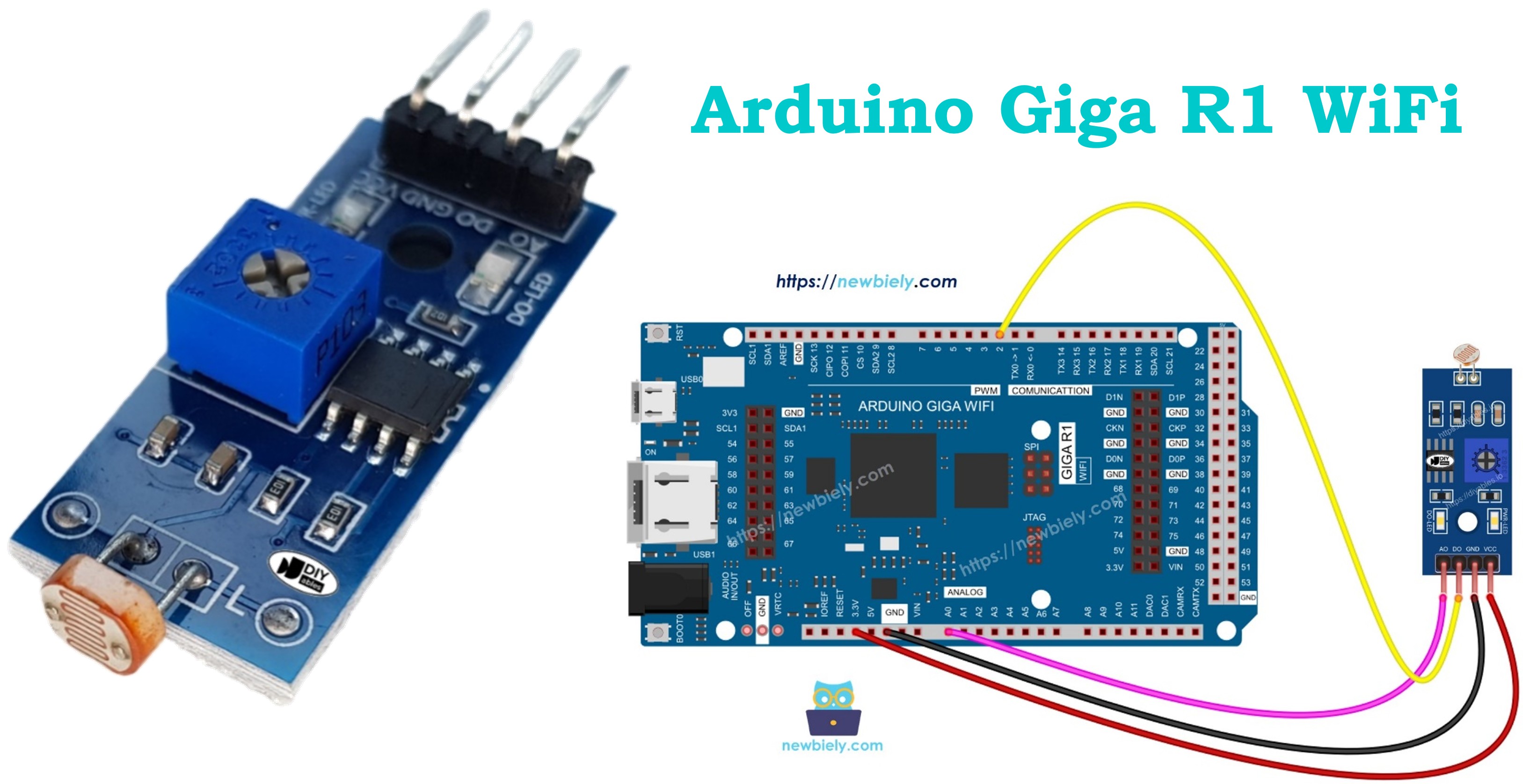
Arduino Giga R1 WiFi LDR Module
This guide covers LDR light sensor module implementation with the Arduino Giga R1 WiFi. The LDR (Light Dependent Resistor) module provides dual output modes: digital threshold detection and analog measurement for continuous light level monitoring.
This tutorial demonstrates configuration of both digital and analog output modes, threshold adjustment, and robust code for reliable light sensing.
Afterward, you can modify the code to activate an LED or a light bulb (via a relay) when it detects light.
If you prefer a light sensor in its raw form, I suggest exploring the tutorial on the Arduino - Light Sensor.
Hardware Preparation
Or you can buy the following kits:
| 1 | × | DIYables Sensor Kit (18 sensors/displays) |
Additionally, some of these links are for products from our own brand, DIYables .
Overview of LDR Light Sensor Module
The LDR light sensor module integrates a light-dependent resistor (photocell) with signal conditioning circuitry, providing both digital threshold detection and analog light level output. Operating on 3.3V to 5V supply, the module draws approximately 15mA.
The module uses a cadmium sulfide (CdS) photoresistor with resistance from ~10kΩ in bright light to >1MΩ in darkness. The integrated comparator circuit (typically LM393) converts the analog resistance change to a clean digital output. Response time is 20-30ms for light-to-dark transition and 200-400ms for dark-to-light recovery. The onboard potentiometer enables threshold adjustment from ~10 lux to 1000 lux.
Pinout
The pinout configuration defines each connection point's electrical function and integration requirements with the Arduino Giga R1 WiFi. Correct wiring is essential — an incorrect connection may damage the module or produce unreliable readings due to voltage mismatch or signal integrity issues.
The LDR light sensor module includes four pins with specific electrical characteristics:
VCC Pin: Power supply input, 3.3V to 5V DC. Connects to the Arduino Giga R1 WiFi's 5V or 3.3V output to provide regulated power. Current consumption is 10-15mA typical, well within the Arduino's power supply capacity. Requires stable voltage for consistent threshold operation.
GND Pin: Ground reference, 0V potential. Connects to any GND pin on the Arduino Giga R1 WiFi to establish common electrical reference. Essential for proper signal integrity and noise immunity.
DO Pin: Digital output, 3.3V/5V logic levels. TTL/CMOS compatible push-pull output that transitions between HIGH (≥2.4V) and LOW (≤0.8V) states based on light threshold comparison. Connects to any digital input pin on the Arduino Giga R1 WiFi. Output current capacity is 20mA maximum.
AO Pin: Analog output, 0V to VCC range. Provides continuous voltage proportional to light intensity with 12-bit effective resolution. Output impedance is approximately 10kΩ, suitable for direct connection to the Arduino Giga R1 WiFi's high-impedance ADC inputs (pins A0-A7). No pull-up resistors required.
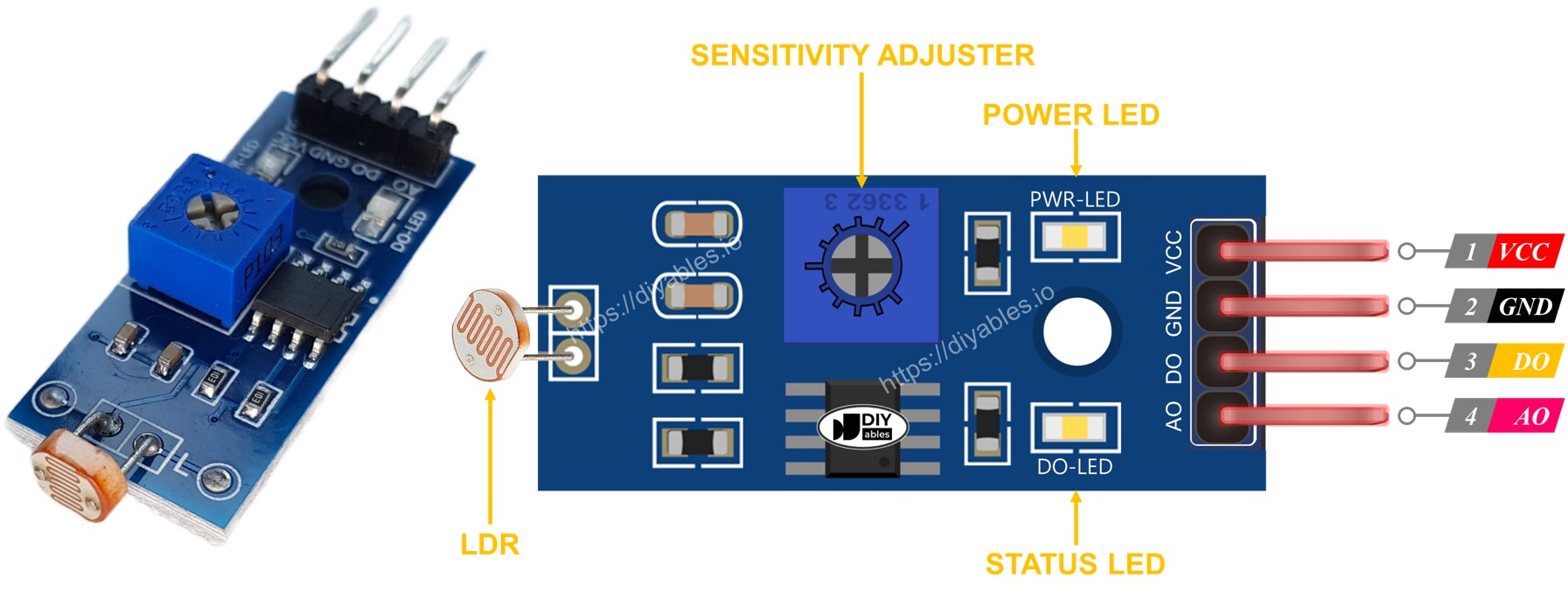
The module features two onboard LED indicators for operational feedback: a red PWR-LED for power status verification and a green DO-LED that mirrors the digital output state. The DO-LED illuminates when light is present (DO pin LOW) and extinguishes in darkness (DO pin HIGH), providing immediate visual confirmation of threshold detection without requiring serial monitor access.
Wiring Diagram
The wiring implementation depends on whether you need digital detection, analog measurement, or both outputs. The Arduino Giga R1 WiFi's flexible GPIO configuration supports multiple connection strategies for different application requirements.
Electrical Note: The diagrams below show the minimum viable connections for development and prototyping. For production or extended use, consider adding 100nF ceramic decoupling capacitors near the VCC pin and implementing proper cable shielding for analog signals in electrically noisy environments.
Power supply connections require attention to current capacity and voltage stability. The module's 10-15mA current draw is easily supported by the Arduino Giga R1 WiFi's onboard regulators. For battery-powered applications, connect to 3.3V output to minimize power consumption. For maximum sensitivity and dynamic range, use the 5V supply connection.
Since the light sensor module has two outputs, you can choose to use one or both of them, depending on what you need.
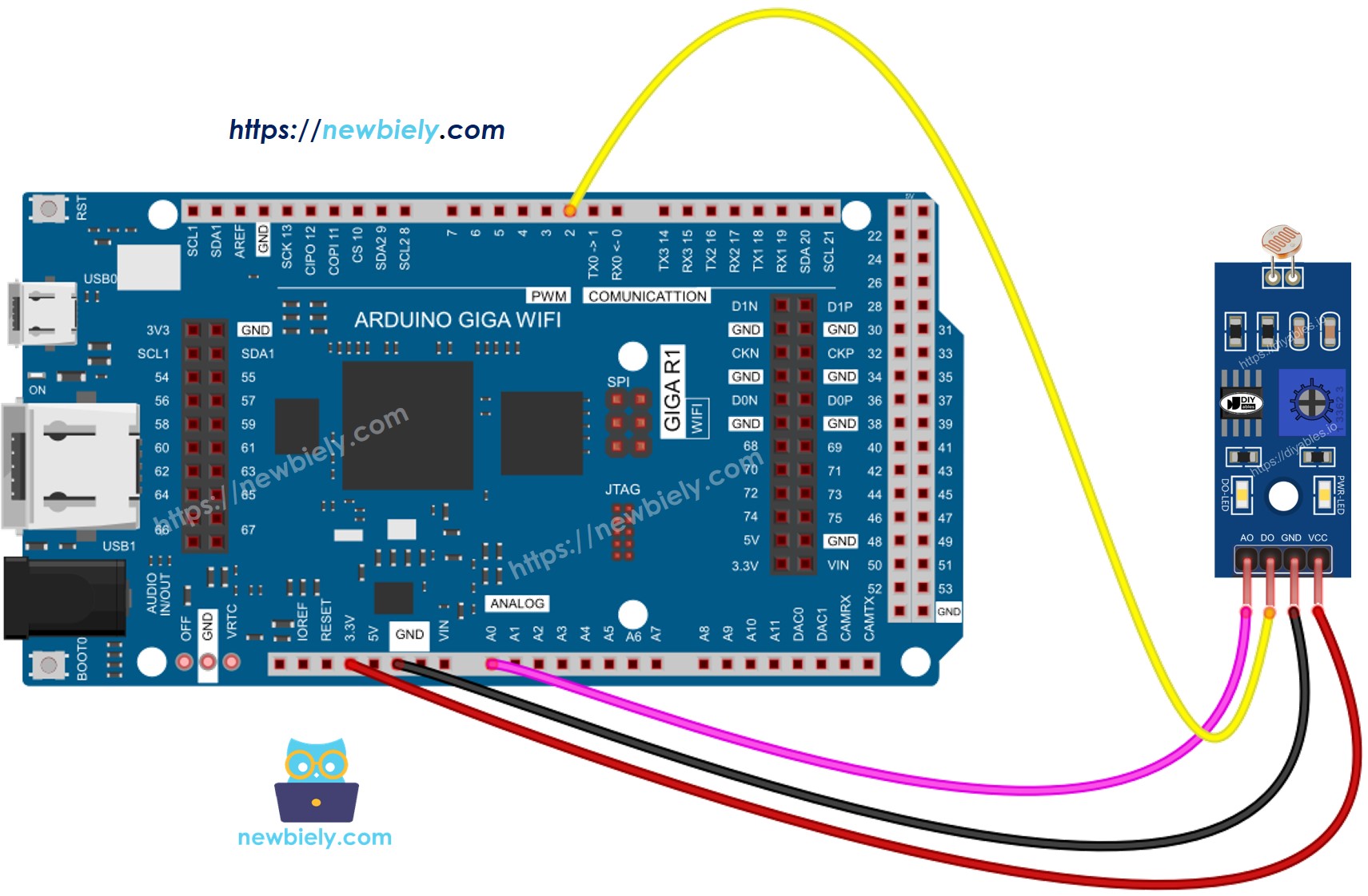
This image is created using Fritzing. Click to enlarge image
| LDR Module Pin | Arduino Giga R1 WiFi Pin |
|---|---|
| VCC | 5V |
| GND | GND |
| DO | Pin 2 (Digital Input) |
| AO | A0 (Analog Input) |
Arduino Code Implementation
The following implementation demonstrates both digital threshold detection and analog light level measurement. The code is structured to handle sensor initialization, data acquisition, and serial communication for monitoring and debugging. Key sections include pin configuration, ADC reading with appropriate timing, and threshold-based decision logic for reliable operation.
The Arduino's built-in functions provide direct hardware access without requiring external libraries. Digital readings use the standard digitalRead() function with hardware debouncing through appropriate delay intervals. Analog readings utilize the 10-bit ADC (12-bit effective on the Arduino Giga R1 WiFi) with analogRead(), providing values from 0-1023 corresponding to 0V-5V input range. Serial communication operates at 9600 baud for reliable data transmission to development environments.
Arduino Code - Read value from DO pin
Detailed Instructions
For initial Arduino Giga R1 WiFi setup, refer to the Arduino Giga R1 WiFi Getting Started guide before proceeding.
- Open Arduino IDE: Launch the Arduino IDE and verify the Arduino Giga R1 WiFi board is selected in Tools > Board menu. Ensure the correct COM port is selected for USB communication.
- Copy and Upload Code: Copy the above code into a new sketch and upload to the Arduino Giga R1 WiFi. The upload process should complete without errors, indicating successful compilation and transfer.
- Open Serial Monitor: Launch the Serial Monitor (Tools > Serial Monitor) and set baud rate to 9600. You should see continuous output indicating the initial sensor state.
- Test Light Detection: Cover and uncover the LDR light sensor module with your hand or opaque object. The digital output should toggle between "The light is present" and "The light is NOT present" messages.
- Adjust Sensitivity: If the LED indicator remains constantly on or off regardless of lighting conditions, rotate the onboard potentiometer clockwise to decrease sensitivity (require brighter light to trigger) or counterclockwise to increase sensitivity (trigger in dimmer light).
- Verify Operation: Confirm the DO-LED on the module illuminates when light is present (DO pin reads LOW) and extinguishes in darkness (DO pin reads HIGH). This provides immediate visual feedback of threshold detection.
Technical Note: The digital output uses a comparator with hysteresis to prevent oscillation near the threshold. Response time is approximately 50ms for light-to-dark transitions and 100ms for dark-to-light transitions due to the photoresistor's inherent recovery characteristics.
Please keep in mind that if you notice the LED status remaining on constantly or off even when there is light, you can adjust the potentiometer to fine-tune the light sensitivity of the sensor.
Now we can customize the code to activate an LED or a light when the light is detected, or even make a servo motor rotate. You can find more information and step-by-step instructions in the tutorials provided at the end of this tutorial.
Arduino Code - Read value from AO pin
Detailed Instructions
Ensure the Arduino IDE is configured for the Arduino Giga R1 WiFi before following these steps. See the Getting Started guide if needed.
- Load Analog Code: Copy the analog reading code into Arduino IDE and upload to the Arduino Giga R1 WiFi. Verify successful compilation and upload completion.
- Configure Serial Monitor: Open Serial Monitor and set baud rate to 9600. You should observe continuous numeric values representing light intensity levels.
- Test Light Response: Cover and uncover the LDR sensor module while monitoring the serial output. Values should decrease in bright light (typically 50-200) and increase in darkness (typically 800-1000).
- Calibrate Range: Note the minimum values in bright light and maximum values in complete darkness. This establishes the operational range for your specific lighting environment and enables threshold programming.
- Verify ADC Operation: Confirm smooth value transitions without erratic jumps. The Arduino Giga R1 WiFi's enhanced ADC should provide stable readings with minimal noise compared to standard Arduino boards.
- Document Thresholds: Record typical light and dark values for your application. These will be used for implementing custom light-activated control systems in future projects.
Technical Note: The analog output provides 10-bit resolution (0-1023) with the Arduino Giga R1 WiFi's standard ADC configuration. For applications requiring higher precision, consider implementing oversampling techniques or utilizing the board's advanced ADC features for increased effective resolution.
Application Ideas
Automatic Lighting Control System: Implement smart lighting that activates LED strips or relay-controlled lamps based on ambient light levels. The Arduino Giga R1 WiFi's WiFi capability enables remote monitoring and control through web interfaces or mobile applications for intelligent building automation.
Solar Panel Tracking Enhancement: Use the LDR module as a feedback sensor in solar tracking systems to optimize panel orientation. The analog output provides precise light intensity data for maximum power point tracking algorithms, while the Arduino Giga R1 WiFi can log performance data and communicate with energy management systems.
Greenhouse Environmental Monitoring: Deploy multiple LDR modules throughout greenhouse installations to monitor light distribution and automate shade cloth deployment. The dual-core architecture of the Arduino Giga R1 WiFi enables simultaneous sensor polling and WiFi data transmission for real-time agricultural monitoring systems.
Security System Light Detection: Create perimeter security sensors that detect changes in ambient light patterns caused by moving shadows or artificial illumination. Integration with the Arduino Giga R1 WiFi's connectivity features allows instant alerts and remote monitoring capability for comprehensive security solutions.
Photography Equipment Automation: Build automatic camera trigger systems for time-lapse photography or wildlife monitoring that respond to specific lighting conditions. The precise analog readings enable sophisticated exposure control algorithms, while onboard data logging capabilities capture environmental conditions.
Industrial Process Control: Implement quality control systems in manufacturing that detect proper illumination for optical inspection processes. The reliable digital output can trigger production line controls, while analog data provides feedback for maintaining optimal lighting conditions in industrial automation systems.
Challenge Yourself
Challenge: Implement dual-threshold detection with hysteresis to eliminate flickering at boundary conditions. Add HIGH and LOW threshold values with a 50-unit deadband to create stable switching behavior.
Challenge: Create a data logging system that records light intensity values to the Arduino Giga R1 WiFi's onboard storage every 10 seconds. Include timestamp functionality and implement CSV file format for easy data analysis in spreadsheet applications.
Challenge: Develop a WiFi-enabled light monitoring station that publishes sensor readings to an MQTT broker every 30 seconds. Utilize the Arduino Giga R1 WiFi's wireless capabilities to create IoT dashboards for remote light level monitoring.
Challenge: Build a solar-powered weather station incorporating the LDR module alongside temperature and humidity sensors. Implement sleep modes and optimize power consumption for extended battery operation while maintaining WiFi connectivity for periodic data uploads.
Challenge: Design an adaptive lighting control system using both analog and digital outputs. Create algorithms that gradually adjust LED brightness based on analog readings while using digital output for instant on/off control, providing smooth transitions and energy efficiency optimization.