Arduino Giga R1 WiFi Rain Sensor
This comprehensive tutorial covers rain sensor implementation with the Arduino Giga R1 WiFi — from hardware setup to complete working code for both digital detection and analog measurement. The rain sensor provides dual-output capabilities for detecting precipitation presence and measuring water accumulation levels, making it an essential component for weather monitoring, irrigation control, and automated systems.
The Arduino Giga R1 WiFi's dual-core architecture and expanded memory capacity make it exceptionally well-suited for rain sensing applications that require simultaneous data processing and wireless connectivity. This board can handle complex algorithms for rainfall pattern analysis while maintaining real-time responsiveness. The integrated WiFi capability enables remote monitoring and data logging to cloud services, essential for agricultural and environmental monitoring systems.
Rain sensors find extensive use across multiple industries: agricultural automation systems for irrigation control, automotive applications for windshield wiper activation, building management for automated canopy deployment, and meteorological stations for precipitation measurement. The sensor's dual analog/digital output architecture provides flexibility for both threshold-based alerts and continuous monitoring applications.
This tutorial walks through complete implementation of both digital rain detection and analog rainfall measurement, including proper wiring techniques to maximize sensor lifespan, code examples for both output modes, and practical considerations for real-world deployment. You'll learn to minimize electrochemical corrosion through smart power management and implement robust sensing algorithms suitable for production environments.
Hardware Preparation
Or you can buy the following kits:
| 1 | × | DIYables Sensor Kit (18 sensors/displays) |
Additionally, some of these links are for products from our own brand, DIYables .
Overview of Rain Sensor
The rain sensor is a resistive-type precipitation detection device designed for measuring water accumulation and presence detection in outdoor environments. Operating on the principle of conductivity variation, it provides reliable rainfall detection with adjustable sensitivity thresholds and dual-output capability for diverse applications.
The sensor operates within a 3.3V to 5V supply range with typical current consumption of 15mA during active sensing. Response time is approximately 1 second for water detection, with analog output resolution dependent on the accumulation area of the sensing pad. The digital output provides hysteresis to prevent false triggering during marginal conditions, with threshold adjustment via an onboard potentiometer spanning the full analog range.
Operating temperature range extends from -10°C to +70°C, suitable for most outdoor installations. The sensing mechanism relies on water bridging exposed copper traces, creating a conductive path that varies with water film thickness and coverage area. This approach provides both digital presence detection and analog quantity measurement from a single sensing element.
Integration with the Arduino Giga R1 WiFi leverages the board's high-resolution ADC for precise analog measurements and multiple GPIO pins for power management techniques that extend sensor lifespan. The board's dual-core capability enables simultaneous sensor monitoring and data transmission, essential for real-time weather monitoring applications.
The rain sensor includes two primary components: the sensing pad for outdoor exposure and the electronic module for signal conditioning and Arduino interface. This modular design allows flexible installation while maintaining electrical isolation between the sensing element and control electronics.
The sensing pad
The sensing pad serves as the primary detection element, featuring parallel copper traces arranged in an interdigitated pattern to maximize sensitivity per unit area. The traces are divided into power and sense groups, electrically isolated until bridged by conductive water films. The copper traces are gold-plated for corrosion resistance, though prolonged exposure to electrolytic conditions will gradually degrade performance.
Sensing area typically measures 40mm x 60mm, providing adequate detection surface for most applications. The trace spacing of approximately 1.2mm ensures sensitivity to light water films while maintaining structural integrity. The PCB substrate uses FR4 material with conformal coating on non-sensing areas to prevent false conductivity paths.
Installation considerations include mounting angle (typically 15-30 degrees from horizontal) for proper drainage and positioning away from sources of electromagnetic interference. The pad connects to the electronic module via a standard 3-wire interface, allowing remote mounting up to several meters away with appropriate cable selection.
The electronic module
The electronic module conditions the raw conductivity signal from the sensing pad into standardized digital and analog outputs compatible with Arduino input specifications. Operating from 3.3V to 5V supply, it incorporates signal amplification, noise filtering, and threshold comparison circuits for reliable operation.
Key specifications include:
- VCC pin: Supply voltage input, 3.3V to 5V DC, maximum 20mA consumption
- GND pin: Ground reference, connects to system ground (0V)
- DO pin: Digital output, CMOS logic levels (0V/VCC), active-low rain detection
- AO pin: Analog output, 0V to VCC range, inversely proportional to water accumulation
The module incorporates two LED indicators: PWR-LED for supply status (continuously on when powered) and DO-LED for rain state indication (illuminated during rain detection). The onboard potentiometer adjusts digital threshold from approximately 10% to 90% of full-scale analog range, allowing field calibration for varying environmental conditions.
Internal circuitry includes input protection against overcurrent and reverse polarity, though direct lightning strikes or high-voltage transients may cause permanent damage. Signal conditioning provides approximately 1kΩ output impedance on both analog and digital outputs, compatible with Arduino's high-impedance inputs without additional buffering.
How It Works
The rain detection mechanism operates on resistive sensing principles. Dry copper traces exhibit infinite resistance between power and sense connections. Water accumulation creates conductive bridges, reducing inter-trace resistance proportionally to water film coverage and thickness.
For the digital output (DO pin):
- The built-in comparator references the analog signal against the potentiometer-set threshold
- When conductivity exceeds the threshold (indicating sufficient water presence), DO outputs LOW (0V) and DO-LED illuminates
- When conductivity falls below threshold (dry condition), DO outputs HIGH (VCC) and DO-LED extinguishes
- Hysteresis prevents oscillation during marginal conditions, providing stable output transitions
For the analog output (AO pin):
- Output voltage varies continuously from near-VCC (dry) to near-0V (fully wetted)
- Typical dry reading: 95-98% of VCC (Arduino analogRead ~1000-1023 at 5V)
- Typical saturated reading: 5-10% of VCC (Arduino analogRead ~50-100 at 5V)
- Response follows logarithmic curve due to percolation effects in trace geometry
- Output remains stable for constant water levels, enabling quantitative measurements
The potentiometer adjustment affects only digital threshold determination and has no influence on analog output characteristics, allowing independent optimization of both output modes.
Pinout
The pinout configuration defines the electrical interface between the rain sensor module and Arduino Giga R1 WiFi. Correct wiring is essential for reliable operation — incorrect connections may damage the sensor electronics or produce erratic readings due to improper signal levels.
VCC (Power Supply): DC supply input, 3.3V to 5V range. Connects to Arduino power pin to provide operating voltage for the conditioning circuitry. Maximum current draw 20mA during active sensing operations.
GND (Ground): Ground reference connection, 0V. Must connect to Arduino GND to establish common voltage reference. Poor ground connections will introduce measurement errors and unstable digital outputs.
DO (Digital Output): CMOS digital signal output, active-low configuration. Outputs 0V during rain detection, VCC during dry conditions. Connect to any Arduino digital input pin (D2-D53). Internal output impedance approximately 1kΩ with 5mA drive capability.
AO (Analog Output): Analog voltage output, 0V to VCC range. Voltage inversely proportional to water accumulation on sensing pad. Connect to Arduino analog input pins (A0-A15). Output impedance ~1kΩ, suitable for direct connection to Arduino's high-impedance ADC inputs.
Signal integrity considerations include keeping wire lengths under 1 meter for analog connections to minimize noise pickup and maintaining separation from high-current switching circuits. The Arduino Giga R1 WiFi's 12-bit ADC resolution provides excellent measurement precision for analog rainfall quantification applications.
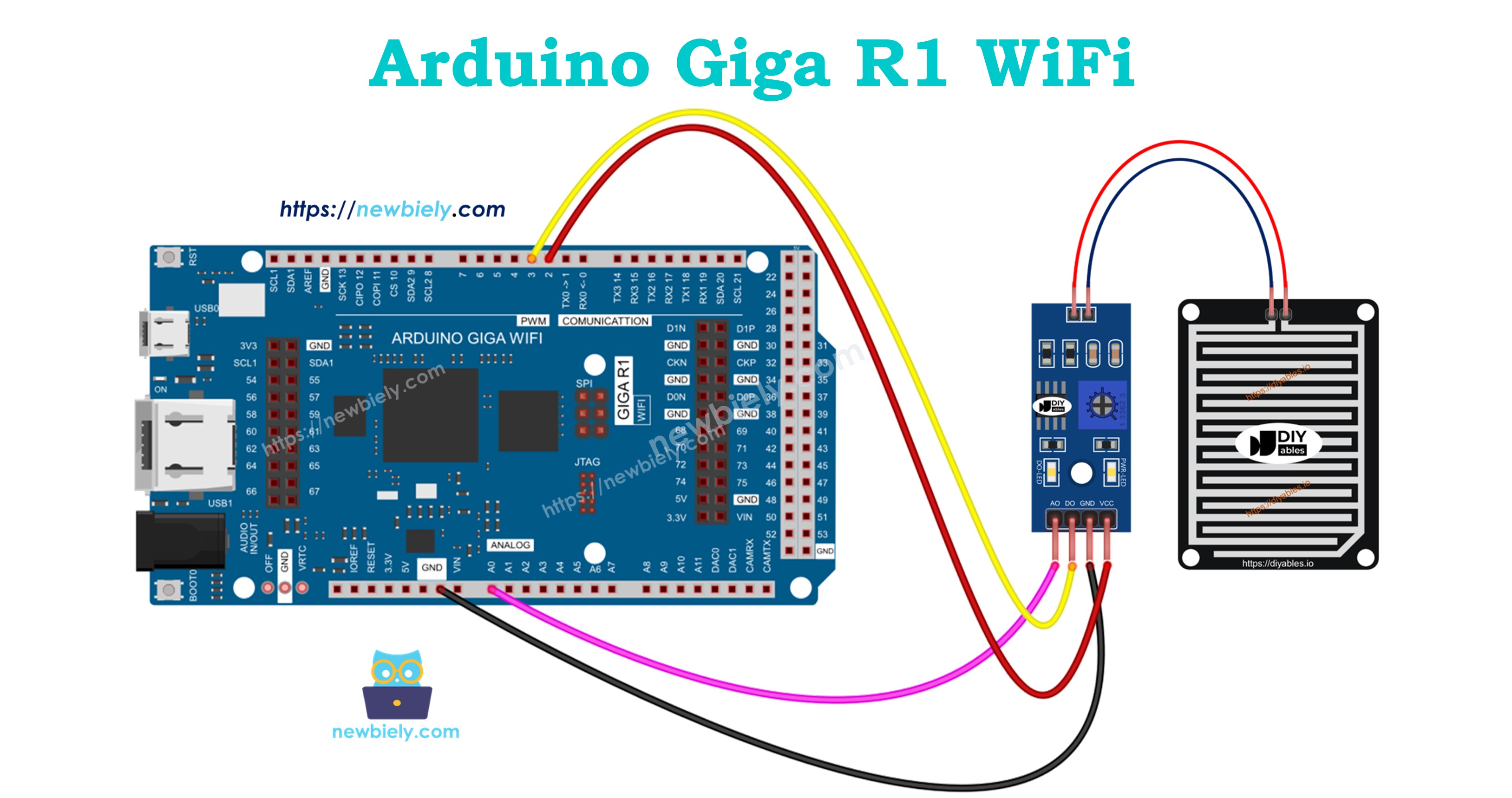
Wiring Diagram
The wiring implementation requires careful attention to power management and signal integrity to ensure reliable long-term operation. The diagrams below demonstrate proper connections for different operational modes, with emphasis on extending sensor lifespan through controlled power switching.
Electrical Note: The diagrams show the minimum viable connections for functional operation. For production or extended outdoor use, consider adding pull-up resistors on digital inputs, ferrite beads on longer cable runs, and transient voltage suppression on exposed lines to protect against electromagnetic interference and weather-related voltage spikes.
A critical consideration for rain sensor deployment involves power management to minimize electrochemical corrosion of the sensing pad. Continuous DC voltage across the copper traces accelerates galvanic corrosion, particularly in the presence of contaminants in rainwater. The recommended approach connects the VCC pin to a digital output pin rather than constant power, enabling on-demand sensing that significantly extends sensor operational life.
Power supply requirements include stable voltage within the 3.3V to 5V range and current capability of at least 25mA to handle inrush and sensing currents. The Arduino Giga R1 WiFi's GPIO pins provide sufficient drive current (20mA continuous) for direct sensor powering, though external switching may be preferable for applications requiring frequent measurements.
Since the rain sensor module provides both digital and analog outputs, implementation flexibility allows selection based on application requirements. Digital-only applications require minimal processing overhead and provide simple presence detection. Analog implementations enable quantitative measurement for precipitation logging and irrigation control algorithms.
| Rain Sensor Pin | Arduino Giga R1 WiFi Pin | Signal Type |
|---|---|---|
| VCC | D2 (Digital Output) | 3.3V/5V Power Control |
| GND | GND | Ground Reference |
| DO | D3 (Digital Input) | Digital Rain Detection |
| AO | A0 (Analog Input) | Analog Rain Level |
The connection table above demonstrates full dual-output implementation. For single-output applications, omit either the DO or AO connection as needed. The power control scheme using D2 as a switching output enables duty-cycled operation, reducing electrochemical effects while maintaining measurement capability.
Code Section
The implementation code demonstrates professional approaches to rain sensor interfacing with the Arduino Giga R1 WiFi. The code structure emphasizes proper sensor power management, signal conditioning, and robust measurement techniques suitable for production environments. Key sections handle initialization of GPIO pins, controlled power sequencing, and measurement algorithms optimized for both digital detection and analog quantification.
The examples utilize standard Arduino libraries with direct register access where performance is critical. Power management routines minimize sensor exposure time to DC voltage, implementing duty-cycled operation that extends sensing pad lifespan significantly compared to continuous-power approaches. Each measurement cycle includes settling time for analog stabilization and digital debouncing for reliable threshold detection.
Digital rain detection provides simple presence/absence determination suitable for alert systems and binary control applications. The analog measurement approach enables quantitative rainfall assessment, supporting applications requiring precipitation intensity data or accumulation tracking over time.
Arduino Code - Read value from DO pin
Detailed Instructions
For initial Arduino Giga R1 WiFi setup, refer to the Arduino Giga R1 WiFi Getting Started guide before proceeding with sensor implementation.
- Open Arduino IDE: Launch the Arduino IDE and ensure the Arduino Giga R1 WiFi board package is properly configured. Verify the correct board selection and COM port assignment in the Tools menu.
- Copy Code: Copy the complete code example above and paste it into a new Arduino IDE sketch. Review the pin assignments and modify if needed for your specific wiring configuration.
- Configure Connections: Wire the rain sensor according to the diagram above, ensuring solid connections and proper power routing. Double-check VCC connection to digital pin 2 for power control functionality.
- Upload Code: Click the Upload button to compile and transfer the code to the Arduino Giga R1 WiFi. Monitor the compilation process for any library dependency issues or syntax errors.
- Initialize Serial Monitor: Open the Serial Monitor at 9600 baud to observe sensor readings. The display should show "Rain is NOT detected" under dry conditions with stable, consistent output.
- Test Detection: Apply small drops of water to the sensing pad surface using a dropper or spray bottle. Observe the immediate transition to "Rain is detected" status, confirming proper threshold setting and digital response.
- Verify Sensitivity: If detection is too sensitive or insensitive, adjust the onboard potentiometer while monitoring serial output. Clockwise rotation typically increases sensitivity to smaller water amounts.
- Confirm LED Operation: Observe the DO-LED on the sensor module during testing. It should illuminate consistently during rain detection states and extinguish during dry conditions, providing visual confirmation of sensor status.
Technical Note: The power control implementation using digital pin switching reduces electrochemical corrosion by approximately 90% compared to continuous power applications. For applications requiring frequent measurements (>1Hz), consider implementing PWM duty cycle control or external power switching to further optimize sensor lifespan while maintaining response time requirements.
Serial Monitor Output
Arduino Code - Read value from AO pin
Detailed Instructions
Ensure the Arduino IDE is configured for the Arduino Giga R1 WiFi before following these analog measurement implementation steps.
- Load Analog Code: Copy the analog measurement code above into a new Arduino IDE sketch. This implementation focuses on quantitative rainfall measurement rather than simple detection.
- Verify Wiring: Confirm the AO pin connection to analog input A0 and proper power control wiring to digital pin 2. Analog measurements require clean, low-noise connections for accurate readings.
- Upload Implementation: Upload the code to the Arduino Giga R1 WiFi and monitor for successful compilation. The analog code includes additional settling time for measurement stability.
- Monitor Baseline: Open Serial Monitor at 9600 baud and observe dry readings. Typical values range from 950-1020 on the Arduino's 10-bit ADC scale, representing minimal conductivity between traces.
- Test Water Response: Apply controlled water amounts to the sensing pad, starting with single drops and progressing to larger quantities. Observe the progressive decrease in analog values corresponding to increased conductivity.
- Calibrate Measurements: Note the analog value range for your specific sensor and water types. Pure water produces higher readings than tap water due to ionic content differences affecting conductivity.
- Verify Consistency: Allow water to evaporate naturally while monitoring readings. Values should gradually increase back toward baseline as the sensing pad dries, demonstrating proper analog response characteristics.
- Document Range: Record the full measurement range from dry to saturated conditions for your specific sensor. This data enables calibration of rainfall intensity algorithms in more complex applications.
Technical Note: The analog output provides 10-bit resolution (0-1023) on the Arduino Giga R1 WiFi's ADC, enabling detection of rainfall intensities down to approximately 0.1% of full scale. For enhanced precision in meteorological applications, consider implementing oversample averaging or external 16-bit ADC integration for sub-millimeter rainfall measurement capabilities.
Serial Monitor Output
Application Ideas
Agricultural Irrigation Control: Implement automated irrigation systems that suspend watering operations during rainfall periods. The Arduino Giga R1 WiFi's WiFi connectivity enables integration with smart irrigation controllers, sending real-time precipitation data to optimize water usage and prevent overwatering of crops and landscapes.
Smart Building Management: Deploy rain sensors for automated building responses including retractable awning control, window closure systems, and HVAC ventilation adjustments. The dual-core architecture allows simultaneous sensor monitoring and building automation protocol communication for seamless integration with existing building management systems.
Weather Station Data Logging: Build comprehensive meteorological monitoring systems combining rain detection with temperature, humidity, and barometric pressure sensors. The Arduino Giga R1 WiFi's expanded memory capacity supports extended data logging periods with local storage before wireless transmission to weather monitoring networks.
Automotive Rain-Sensing Systems: Develop prototype automatic windshield wiper controllers that adjust wiper speed based on rainfall intensity. The analog output enables variable-speed control algorithms, while the board's processing capability supports sophisticated pattern recognition for distinguishing between rain, snow, and debris.
Industrial Environmental Monitoring: Create safety systems for outdoor industrial operations that automatically halt processes or deploy protective covers during precipitation events. The reliable digital output provides fail-safe alerts, while analog measurements enable graduated responses based on rainfall intensity levels.
Research and Educational Platforms: Implement advanced student projects exploring meteorological data collection, wireless sensor networking, and environmental monitoring techniques. The Arduino Giga R1 WiFi's dual-core capability enables real-time data processing experiments and multi-sensor fusion algorithms for comprehensive environmental characterization.
Video Section
The accompanying video tutorial demonstrates complete hardware assembly and live code execution for both digital and analog rain sensor implementations. It covers proper wiring techniques to minimize electrochemical corrosion, potentiometer adjustment procedures for optimal sensitivity, and real-time observation of sensor response to varying water conditions. The demonstration includes serial monitor output interpretation and troubleshooting common installation issues for reliable long-term operation.
Challenge Yourself
Challenge: Implement a rainfall intensity classifier that categorizes precipitation as light, moderate, or heavy based on analog sensor readings. Use moving average filtering to smooth sensor data and prevent false classifications during transitional conditions.
Challenge: Create a wireless rain monitoring network using multiple Arduino Giga R1 WiFi boards with rain sensors positioned at different locations. Implement mesh networking protocols to relay precipitation data from remote sensors to a central monitoring station, handling communication failures and data synchronization automatically.
Challenge: Develop a predictive maintenance system that monitors rain sensor performance over time by tracking baseline analog readings and detection threshold stability. Implement algorithms to detect sensor degradation due to corrosion or contamination, providing advance warning before sensor failure affects system reliability.
Challenge: Build an integrated weather station combining the rain sensor with wind speed, temperature, humidity, and barometric pressure sensors. Implement data fusion algorithms that correlate multiple environmental parameters to provide comprehensive weather analysis and short-term precipitation forecasting capabilities.
Challenge: Design a solar-powered remote rain monitoring system with ultra-low power consumption extending battery life beyond one year. Implement duty-cycle optimization, deep sleep modes, and power harvesting algorithms while maintaining measurement accuracy and wireless connectivity for periodic data transmission.