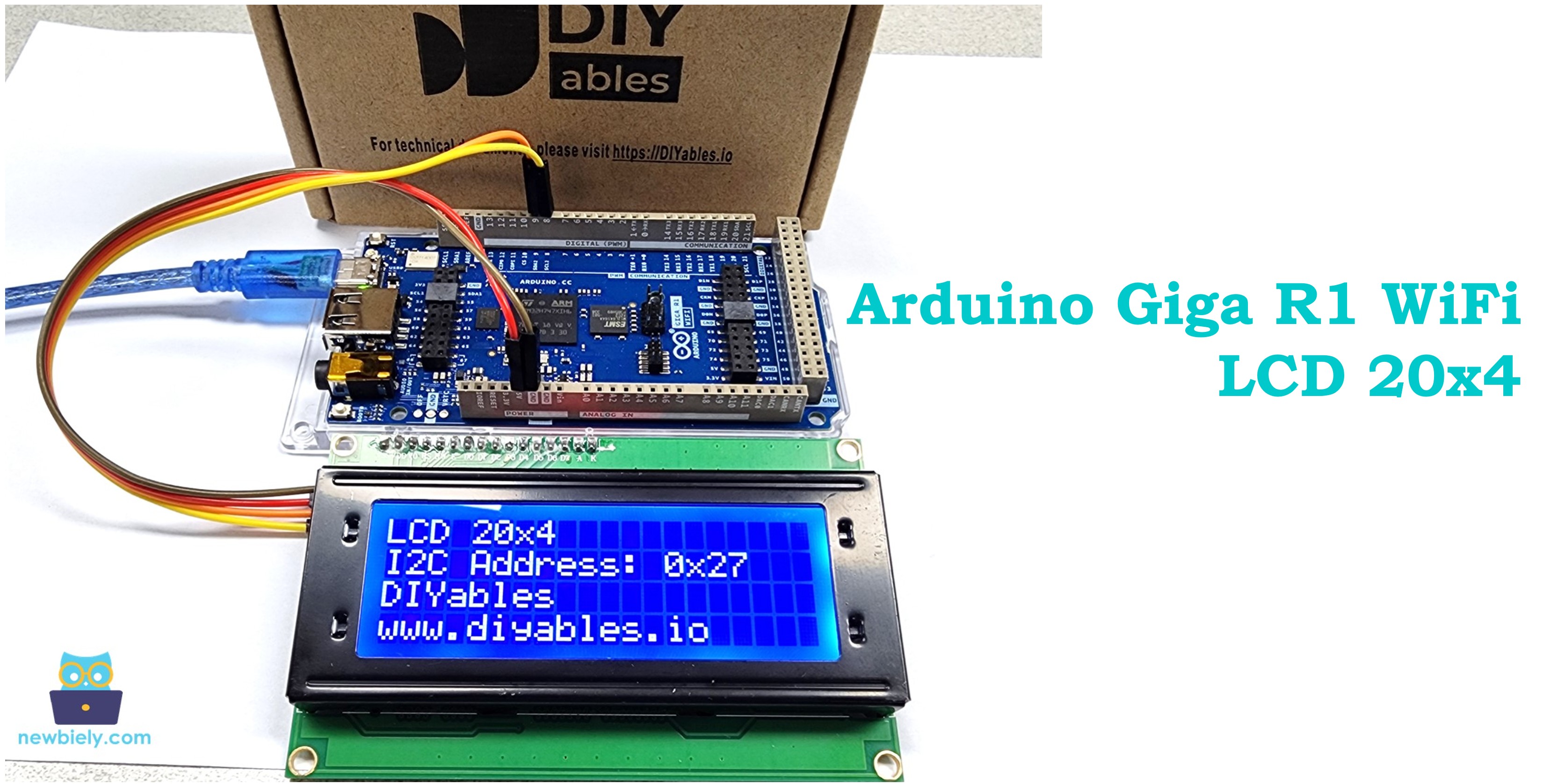
Arduino Giga R1 WiFi LCD 20x4
This guide covers interfacing a 20x4 LCD display with the Arduino Giga R1 WiFi via I2C communication. The LCD I2C 20x4 provides clear text output with minimal wiring complexity.
This tutorial walks through I2C address configuration, coordinate system management, and practical display techniques. You'll implement a working LCD interface that displays formatted text across all four rows.
Hardware Preparation
Or you can buy the following kits:
| 1 | × | DIYables Sensor Kit (18 sensors/displays) |
Additionally, some of these links are for products from our own brand, DIYables .
Buy Note: Alternatively, you can assemble the LCD I2C display using LCD 1602 Display and PCF8574 I2C Adapter Module.
Overview of LCD I2C 20x4
The LCD I2C 20x4 is a character-based display providing 20 columns by 4 rows. The integrated I2C interface module (typically PCF8574) converts the traditional parallel LCD interface to I2C, reducing connections from 6+ pins to just 4 pins.
The display operates on 5V supply with current consumption of 120-150mA including backlight. The I2C interface operates at 100kHz or 400kHz with selectable 7-bit addresses. The HD44780-compatible controller manages character ROM lookup, cursor positioning, and display refresh automatically.
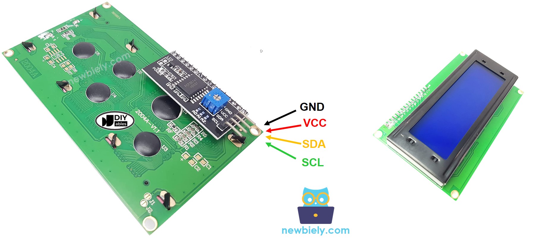
Pinout
The pinout defines the electrical interface between the LCD I2C module and the Arduino Giga R1 WiFi. Correct wiring is essential — an incorrect power connection may damage the LCD module, while swapped I2C lines will prevent communication entirely.
LCD 20x4 I2C uses I2C interface, so it has 4 pins:
- GND pin: Ground reference (0V). Connect to Arduino ground to establish common electrical reference. Maximum current path for backlight return current (~80mA).
- VCC pin: Power supply input (+5V, ±5% tolerance). Supplies both logic and backlight circuits. Total current consumption 120-150mA typical. Connect to Arduino 5V output, which provides up to 500mA on the Giga R1 WiFi.
- SDA pin: I2C Serial Data line (bidirectional, 5V logic levels). Requires pull-up resistor (typically 4.7kΩ, usually integrated on the I2C module). Connect to Arduino SDA2 (Pin 9) on the Giga R1 WiFi.
- SCL pin: I2C Serial Clock line (output from master, 5V logic levels). Also requires pull-up resistor for open-drain operation. Connect to Arduino SCL2 (Pin 8) on the Giga R1 WiFi.
The Arduino Giga R1 WiFi's I2C pins (8, 9) for Wire2 are 5V tolerant and provide hardware I2C peripheral support, ensuring reliable timing and protocol handling. The integrated pull-up resistors on most LCD I2C modules eliminate the need for external components.
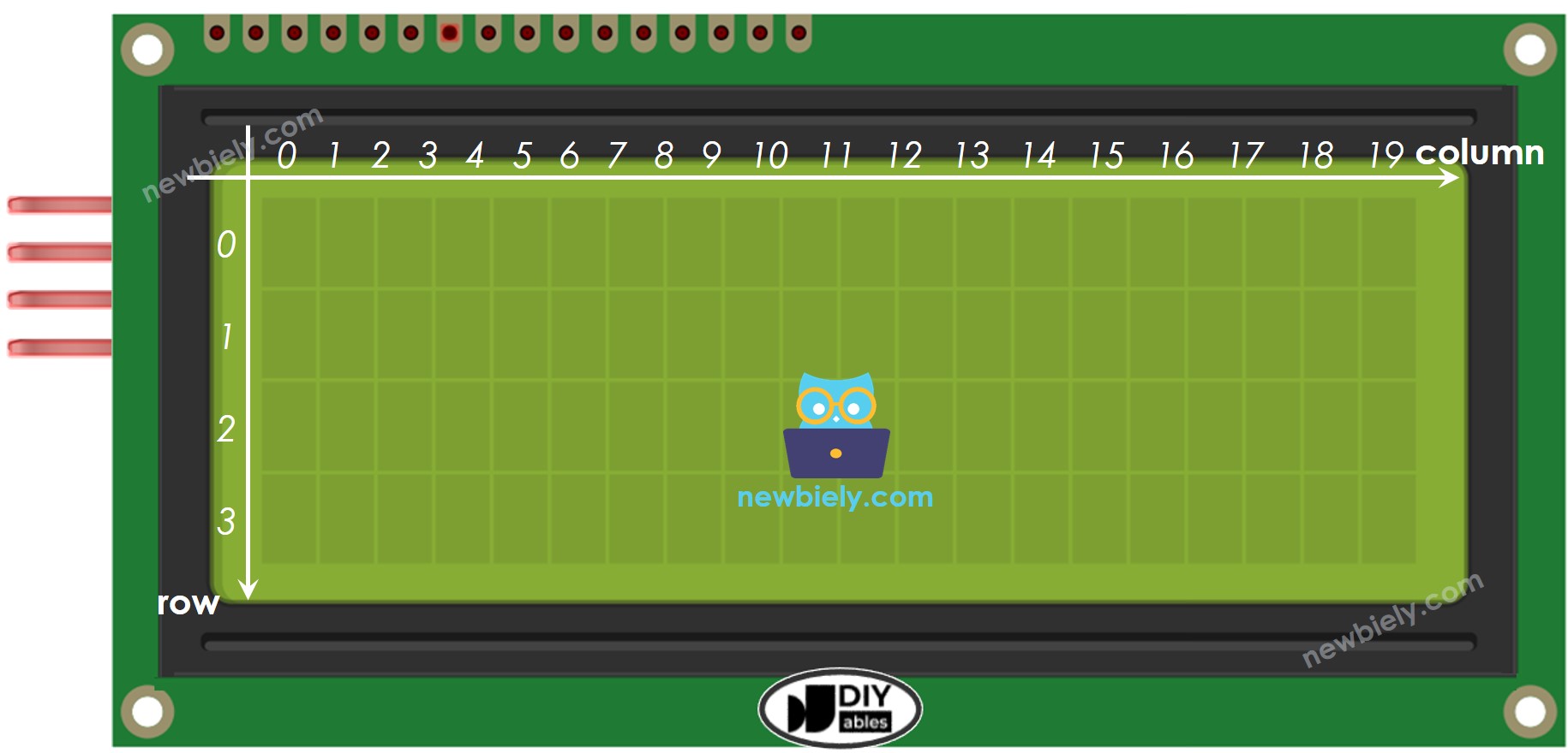
LCD Coordinate
The LCD I2C 20x4 coordinate system provides precise cursor positioning across the display matrix. Understanding this addressing scheme is crucial for accurate text placement and dynamic display updates.
LCD I2C 20x4 includes 20 columns and 4 rows. The columns and rows are indexed from 0, following standard programming conventions. Column addresses range from 0-19 (leftmost to rightmost), while row addresses span 0-3 (top to bottom). The setCursor(column, row) function positions the text cursor at the specified coordinates before printing characters.
Memory mapping follows the HD44780 controller's internal DDRAM (Display Data RAM) structure. Row 0 occupies addresses 0x00-0x13, Row 1 uses 0x40-0x53, Row 2 maps to 0x14-0x27, and Row 3 corresponds to 0x54-0x67. The DIYables_LCD_I2C library handles this address translation automatically when using column/row coordinates.
Character positioning affects subsequent print operations — text flows from the cursor position rightward until reaching the row boundary. Text exceeding the 20-character row limit wraps according to the controller's internal addressing, which may not correspond to the next visual row.
Wiring Diagram
The wiring implementation connects the LCD I2C module to the Arduino Giga R1 WiFi's dedicated I2C peripheral pins. This configuration provides hardware-accelerated I2C communication with automatic timing control and error detection.
Electrical Note: The diagram shows the minimum viable connection for development and prototyping. For production applications or extended operation, consider adding a 100µF electrolytic capacitor between VCC and GND near the LCD module to improve power supply stability and reduce backlight-induced voltage fluctuations.
The I2C bus requires only four connections, significantly reducing wiring complexity compared to parallel LCD interfaces. The Arduino Giga R1 WiFi's 5V output provides sufficient current (500mA available) for the LCD's power requirements including backlight operation. The hardware I2C peripheral on pins 8/9 (Wire2) ensures reliable communication timing and frees the CPU for other tasks.
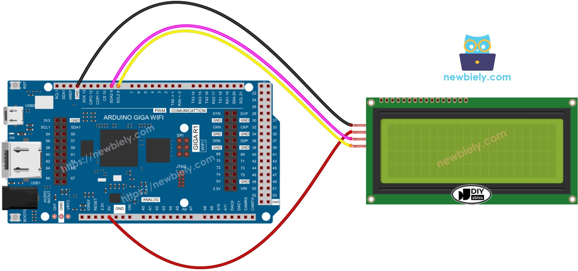
This image is created using Fritzing. Click to enlarge image
| LCD I2C | Arduino Giga R1 WiFi, Nano | Arduino Giga R1 WiFi |
|---|---|---|
| Vin | 5V | 5V |
| GND | GND | GND |
| SDA | A4 | 9 (SDA2) |
| SCL | A5 | 8 (SCL2) |
How To Program For LCD I2C
The following implementation demonstrates I2C LCD control using the DIYables_LCD_I2C library. This library abstracts the low-level I2C communication protocol and HD44780 command structure, providing high-level functions for display control. The code structure initializes the I2C interface, configures the display parameters, and provides methods for cursor positioning and text output.
The DIYables_LCD_I2C library handles I2C address management, command/data byte formatting, and timing requirements automatically. It manages the PCF8574 I2C expander's pin assignments and implements the necessary setup sequences for HD44780 controller initialization. Key library functions include display initialization, backlight control, cursor positioning, and character output.
Thanks to the DIYables_LCD_I2C library, using LCD displays becomes straightforward with clear function calls and reliable operation.
- Include the library:
- Declare a DIYables_LCD_I2C object with I2C address, the number of columns, the number of rows:
- Initialize the LCD and configure display parameters:
- Move cursor to the desired position (column_index, row_index):
- Print a message to the LCD:
※ NOTE THAT:
The I2C address of LCD can vary according to the manufacturers. In the code, we used 0x27 that is specified by DIYables manufacturer. Common addresses include 0x27, 0x3F, 0x26, and 0x20. Use I2C scanner code if the address is unknown.
Arduino Code
Detailed Instructions
For initial Arduino Giga R1 WiFi setup, refer to the Arduino Giga R1 WiFi Getting Started guide before proceeding with this LCD I2C implementation.
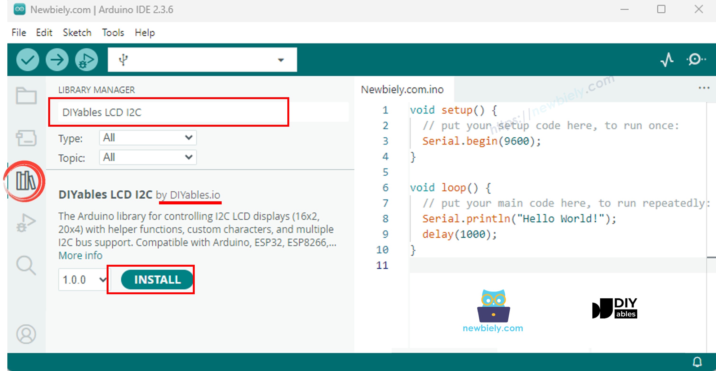
- Install Required Library: Navigate to the Libraries icon on the left bar of the Arduino IDE. Search "DIYables LCD I2C" and find the DIYables_LCD_I2C library by DIYables. Click Install to add the library to your IDE. This library provides optimized I2C communication functions and HD44780 controller management.
- Connect Hardware: Wire the LCD I2C module according to the wiring diagram above. Verify all connections, especially power (VCC to 5V, GND to GND) and I2C lines (SDA2 to Pin 9, SCL2 to Pin 8). Incorrect power connections may damage the display module.
- Upload Code: Copy the provided Arduino code and open it in Arduino IDE. Verify the I2C address (0x27) matches your LCD module specification. Click Upload to transfer the code to the Arduino Giga R1 WiFi. The IDE should confirm successful upload without compilation errors.
- Verify Display Operation: The LCD should display four lines of text immediately after upload: "LCD 20x4", "I2C Address: 0x27", "DIYables", and "www.diyables.io". If the display remains blank, check I2C address, wiring connections, and power supply status.
- Test Text Modification: Modify the text strings in the code and re-upload to verify cursor positioning and character display. Try different setCursor coordinates to understand the 20x4 addressing system. Test with longer strings to observe text wrapping behavior.
- Configure I2C Address: If the display doesn't respond, the I2C address may be different. Common alternatives include 0x3F, 0x26, or 0x20. Use an I2C scanner sketch to detect the correct address, then update the lcd object declaration accordingly.
Technical Note: The Arduino Giga R1 WiFi's hardware I2C peripheral automatically manages clock stretching and bus arbitration. For applications requiring multiple I2C devices, ensure unique addresses and consider using the secondary I2C bus (Wire1) if available to distribute communication load.
Serial Monitor Output
Application Ideas
Industrial Process Display: Implement real-time monitoring systems displaying sensor readings, process status, and alarm conditions. The Arduino Giga R1 WiFi's dual-core architecture enables simultaneous data acquisition and display updates without blocking I2C communication to the LCD.
Data Logger Interface: Create standalone data logging systems with LCD status display showing current readings, SD card status, and WiFi connectivity. The Giga R1 WiFi's expanded memory supports extensive data buffering while maintaining continuous display updates.
Environmental Monitoring Station: Build weather stations or greenhouse controllers displaying temperature, humidity, pressure, and control system status. Multiple sensor integration benefits from the Giga R1 WiFi's numerous ADC channels and I2C bus capacity.
Access Control System: Develop entry control systems with LCD feedback for user prompts, status messages, and access logging. The integrated WiFi capability enables remote monitoring and cloud-based access log management.
Equipment Status Dashboard: Create maintenance displays for industrial equipment showing operating hours, fault codes, maintenance schedules, and performance metrics. The robust I2C implementation ensures reliable display operation in harsh industrial environments.
IoT Configuration Interface: Implement local configuration interfaces for WiFi-connected devices, displaying network status, configuration parameters, and diagnostic information. The dual-core processor handles WiFi communication while maintaining responsive LCD interface updates.
Video Tutorial
The accompanying video demonstrates the complete hardware assembly process and live code execution. It covers I2C address detection techniques, systematic wiring verification, and troubleshooting common connection issues. The video also shows the expected LCD initialization sequence and demonstrates text positioning across all four display rows.
Challenge Yourself
Challenge: Implement dynamic text scrolling for messages longer than 20 characters per row. Create functions to scroll text horizontally across rows with adjustable timing delays and smooth character transitions.
Challenge: Add real-time clock display functionality using the Arduino Giga R1 WiFi's RTC capabilities. Display current time, date, and elapsed runtime with automatic updates every second while maintaining other display content.
Challenge: Create a multi-screen menu system with navigation controls using push buttons. Implement screen transitions, parameter adjustment interfaces, and persistent settings storage using the Giga R1 WiFi's EEPROM emulation.
Challenge: Integrate sensor data display with automatic range scaling and units conversion. Display temperature, pressure, or other sensor readings with automatic decimal place adjustment and engineering unit formatting.
Challenge: Develop a WiFi-enabled information display that receives and displays messages from a web server or MQTT broker. Use the Giga R1 WiFi's WiFi capabilities to create a remote-controlled message board with network status indication.