Arduino Giga R1 WiFi Ultrasonic Sensor
This guide covers ultrasonic distance sensing with the Arduino Giga R1 WiFi — from hardware setup to noise-filtered measurements. The HC-SR04 ultrasonic sensor provides non-contact distance measurement from 2cm to 400cm with 3mm accuracy, making it ideal for robotics, automation, and proximity detection applications.
The Arduino Giga R1 WiFi's dual-core STM32H747XI processor delivers precise timing control essential for ultrasonic sensor operation. With its 64MHz system clock and dedicated timer peripherals, it can generate accurate microsecond pulses and measure echo return times with high resolution. The generous 8MB Flash and 1MB RAM enable sophisticated filtering algorithms and data logging capabilities that simpler microcontrollers cannot support.
This tutorial demonstrates complete implementation including hardware wiring, timing-critical code, distance calculation algorithms, and advanced noise filtering techniques. You'll learn the underlying ultrasonic measurement principles, implement reliable distance readings, and apply signal processing methods to eliminate measurement artifacts common in real-world deployments.
The documentation covers sensor operation theory, electrical integration with the Arduino Giga R1 WiFi's GPIO architecture, complete working code examples, and practical applications ranging from collision avoidance systems to automated level monitoring. By the end, you'll have a robust ultrasonic sensing solution ready for integration into larger embedded systems projects.
Hardware Preparation
Or you can buy the following kits:
| 1 | × | DIYables Sensor Kit (18 sensors/displays) |
Additionally, some of these links are for products from our own brand, DIYables .
Overview of Ultrasonic Sensor
The HC-SR04 is a precision ultrasonic distance sensor designed for non-contact ranging applications from 2cm to 400cm. This sensor operates on the time-of-flight principle, emitting 40kHz ultrasonic pulses and measuring the echo return time to calculate distance with 3mm resolution accuracy.
The sensor integrates an ultrasonic transmitter, receiver, and signal processing circuitry in a compact module. Operating voltage ranges from 4.5V to 5.5V with typical current consumption of 15mA during measurement cycles. The measurement cycle time is 60ms maximum, enabling refresh rates up to 16Hz for continuous distance monitoring applications.
The HC-SR04 uses acoustic wave propagation at approximately 343 m/s in standard atmospheric conditions (20°C, sea level). Temperature variations affect sound speed by approximately 0.17% per degree Celsius, which may require compensation in precision applications. The sensor's beam angle is approximately 15 degrees, creating an effective detection cone that determines the minimum target size for reliable detection.
Integration with the Arduino Giga R1 WiFi leverages the microcontroller's precise timing capabilities for trigger pulse generation and echo measurement. The STM32H747XI processor's dedicated timer peripherals provide microsecond-level accuracy essential for reliable distance calculations. The sensor's 5V operation aligns perfectly with the Arduino Giga R1 WiFi's mixed-voltage I/O architecture, eliminating the need for level shifting circuits.
Compared to infrared or laser distance sensors, ultrasonic sensors offer advantages in measuring transparent or highly reflective surfaces, though they may struggle with sound-absorbing materials like fabric or foam. The acoustic approach makes them suitable for outdoor applications where optical sensors might be affected by ambient light conditions.
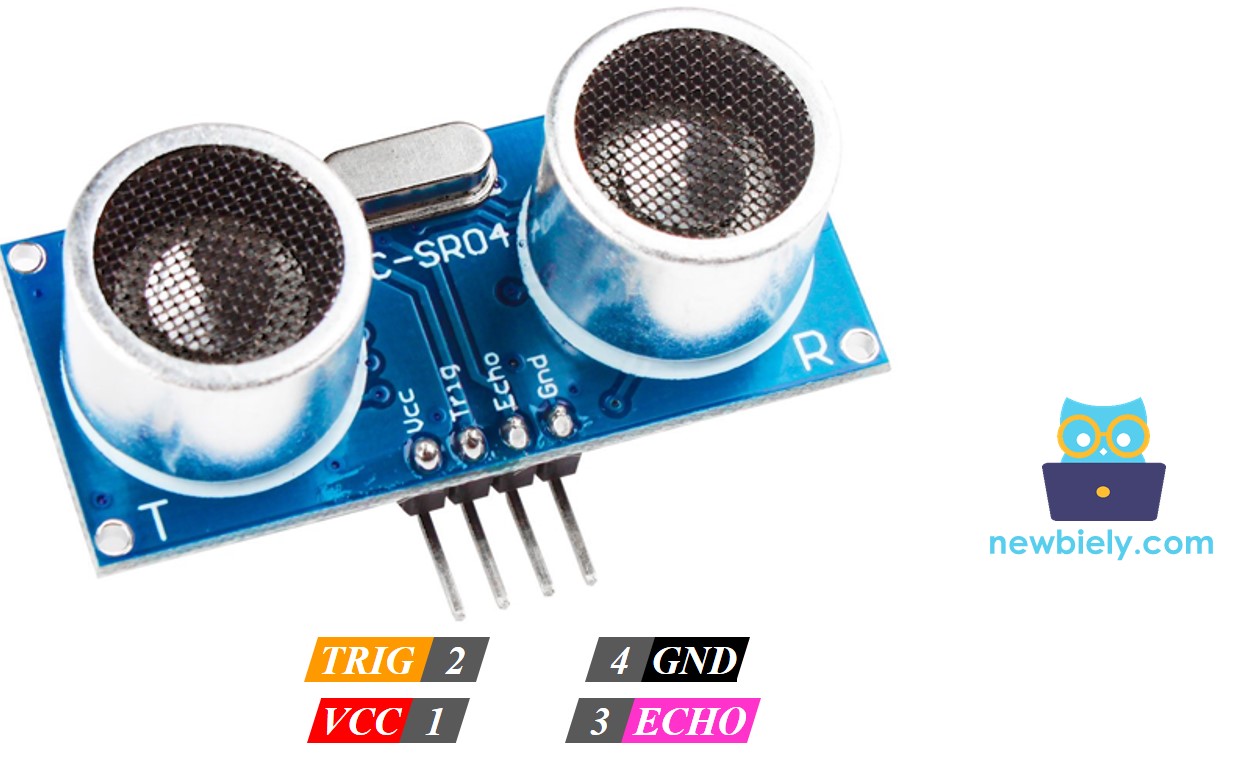
Pinout
The pinout maps each physical connection to its electrical function. Correct wiring is essential — an incorrect connection may damage the component or produce unreliable readings. The HC-SR04's four-pin configuration provides power, ground, and bidirectional communication with the host microcontroller.
The ultrasonic sensor HC-SR04 includes four pins:
- VCC pin: +5V power supply input, 15mA typical current. Connects to Arduino 5V rail to provide sensor operating power. Voltage range: 4.5V to 5.5V maximum.
- GND pin: Ground reference, 0V. Connects to Arduino GND to establish common electrical reference for all signals.
- TRIG pin: Digital input, 5V logic level. Receives trigger pulse from Arduino GPIO pin. Requires 10µs HIGH pulse to initiate measurement cycle. Input impedance >10kΩ.
- ECHO pin: Digital output, 5V logic level. Sends timing pulse to Arduino GPIO pin. Pulse width corresponds to ultrasonic wave round-trip time. Output drive current: 4mA maximum.
The TRIG and ECHO pins operate at 5V logic levels, compatible with the Arduino Giga R1 WiFi's 5V-tolerant GPIO pins. No external pull-up resistors are required as the sensor provides adequate output drive current. For extended cable runs beyond 30cm, consider adding 100Ω series resistors on both TRIG and ECHO lines to reduce signal reflections and improve noise immunity.
Common wiring errors include reversing TRIG and ECHO connections (resulting in no readings), insufficient power supply current capacity (causing erratic measurements), or poor ground connections (introducing noise into timing measurements).
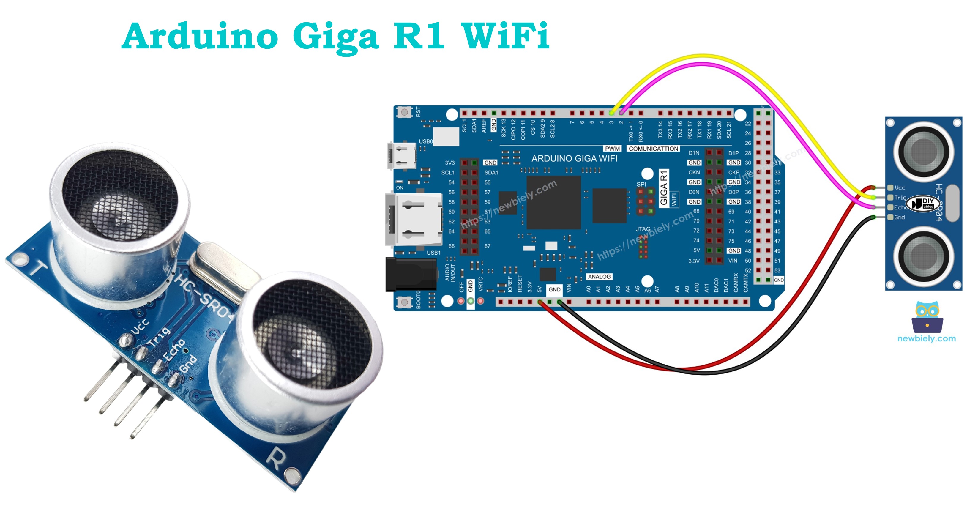
Wiring Diagram
The wiring implementation connects the HC-SR04 sensor to the Arduino Giga R1 WiFi's digital GPIO pins for trigger control and echo measurement. The configuration uses separate pins for transmit and receive functions, enabling full-duplex communication timing.
Electrical Note: The diagram below shows the minimum viable connection for development and testing. For production or extended use, consider adding 100µF capacitor across VCC and GND near the sensor to reduce power supply noise, and keep wire lengths under 20cm to minimize signal integrity issues.
This image is created using Fritzing. Click to enlarge image
Power supply considerations: The HC-SR04 draws peak current of 15mA during ultrasonic pulse transmission. The Arduino Giga R1 WiFi's onboard regulator can easily supply this current, but ensure total system current remains within the USB power budget of 500mA when using USB power.
| Component Pin | Arduino Giga R1 WiFi Pin |
|---|---|
| VCC | 5V |
| GND | GND |
| TRIG | Digital Pin 9 |
| ECHO | Digital Pin 8 |
How It Works
The ultrasonic distance measurement process involves precise timing coordination between the Arduino Giga R1 WiFi and the HC-SR04 sensor. Understanding this timing sequence is crucial for reliable implementation and troubleshooting measurement issues.
- Trigger Generation: Arduino generates a 10-microsecond HIGH pulse on the TRIG pin. This pulse must be precisely timed — shorter pulses may not reliably trigger the sensor, while longer pulses waste measurement cycle time.
- Ultrasonic Transmission: The HC-SR04 automatically emits eight 40kHz ultrasonic pulses in a 15-degree cone pattern. The 40kHz frequency provides optimal balance between range and accuracy for most applications.
- Wave Propagation: The ultrasonic wave travels through air at approximately 343 m/s (temperature dependent). The wave reflects off the first significant obstacle in the sensor's beam path and returns to the sensor.
- Echo Detection: The HC-SR04's receiver detects the reflected ultrasonic wave using phase-locked detection circuitry. The sensor's internal signal processing filters ambient noise and validates the received signal strength.
- Pulse Width Modulation: The sensor generates a variable-width pulse on the ECHO pin. The pulse duration directly corresponds to the ultrasonic wave's round-trip travel time, providing a simple time-to-digital conversion.
- Distance Calculation: The Arduino measures the ECHO pulse width using timer-based functions and calculates distance using the known speed of sound. The calculation accounts for the round-trip nature of the measurement.
How to Get Distance From Ultrasonic Sensor
Extracting distance measurements from the HC-SR04 requires executing two precisely timed operations: trigger pulse generation and echo pulse measurement. The Arduino Giga R1 WiFi's timer peripherals provide the microsecond-level accuracy needed for reliable measurements.
The measurement sequence simplifies the six-step process described above into two software-controlled operations:
- Generate Control Signal: Create a 10-microsecond trigger pulse to initiate sensor measurement
- Measure Response: Capture the echo pulse duration and calculate distance using acoustic propagation principles
Distance Calculation
The mathematical relationship between pulse duration and distance derives from basic acoustic wave propagation physics. Accurate calculation requires understanding the round-trip nature of ultrasonic measurement and the temperature dependence of sound velocity.
Physical Parameters:
- The travel time of the ultrasonic wave (μs): travel_time = pulse_duration
- The speed of the ultrasonic wave: speed = SPEED_OF_SOUND = 343 m/s = 0.0343 cm/μs (at 20°C)
Distance Calculation Steps:
- The travel distance of the ultrasonic wave (cm): travel_distance = speed × travel_time = 0.0343 × pulse_duration
- The distance between sensor and obstacle (cm): distance = travel_distance / 2 = 0.0343 × pulse_duration / 2 = 0.01715 × pulse_duration
Temperature Compensation: For applications requiring high accuracy, the speed of sound varies with temperature according to: v = 331.3 + (0.606 × T) where T is temperature in Celsius. This represents approximately 0.17% change per degree Celsius.
Arduino - Ultrasonic Sensor
The Arduino Giga R1 WiFi's STM32H747XI processor provides dedicated hardware timers and GPIO peripherals optimized for precision timing applications like ultrasonic sensing. The implementation leverages two digital pins configured for complementary functions: trigger pulse generation and echo pulse measurement.
GPIO Configuration Requirements:
- TRIG Pin: Configured as digital output to generate 10μs control pulses. Connected to Arduino digital pin with sufficient current drive (typically 20mA) to ensure reliable sensor triggering.
- ECHO Pin: Configured as digital input to measure variable-width pulses from 150μs to 25ms. The Arduino's input capture functionality provides microsecond-level measurement resolution.
The Arduino Giga R1 WiFi's 64MHz system clock enables precise pulse timing generation and measurement. The processor's DMA capabilities allow for non-blocking sensor operations when implementing multiple sensor arrays or real-time systems requiring deterministic timing.
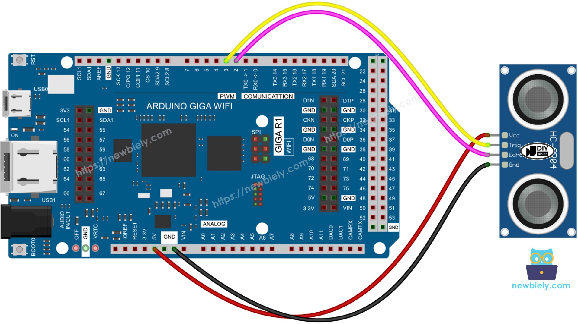
Wiring Diagram
The physical connection implementation establishes reliable electrical communication between the HC-SR04 sensor and Arduino Giga R1 WiFi. Proper wiring ensures signal integrity and measurement accuracy across the full operating range.
Electrical Note: The diagram above shows the minimum viable connection for prototyping and development. For production or extended use, consider adding a 100μF electrolytic capacitor between VCC and GND at the sensor location to decouple power supply transients during ultrasonic pulse transmission, which can introduce measurement noise.
This image is created using Fritzing. Click to enlarge image
Signal Integrity Considerations: Keep wire lengths under 20cm to minimize parasitic capacitance and inductance that can degrade rise/fall times on the TRIG and ECHO signals. For longer connections, use twisted-pair wire with 100Ω characteristic impedance and consider adding 22Ω series termination resistors.
How To Program For Ultrasonic Sensor
Programming the HC-SR04 ultrasonic sensor requires implementing precise timing control for trigger generation and echo measurement. The Arduino Giga R1 WiFi's software interface provides the necessary functions for microsecond-level timing operations.
The implementation focuses on two critical software operations that correspond directly to the sensor's hardware requirements. Understanding these operations enables reliable sensor integration and troubleshooting of timing-related measurement issues.
Trigger Pulse Generation Logic:
Generate a 10-microsecond positive pulse on the Arduino's TRIG pin using digitalWrite() state control and delayMicroseconds() timing functions. The pulse must be precisely 10μs — shorter pulses may not reliably trigger the sensor's internal measurement cycle.
Implementation for pin 9:
Echo Pulse Measurement:
Measure the variable-width pulse duration on the Arduino's ECHO pin using the pulseIn() function. This function employs hardware timer resources to achieve microsecond resolution measurement of pulse widths from 150μs to 25ms.
Implementation for pin 8:
Distance Conversion Algorithm:
Convert the measured pulse duration to distance using the acoustic wave propagation formula. The calculation accounts for the round-trip nature of ultrasonic measurement and uses the standard speed of sound at room temperature.
Error Handling: The pulseIn() function returns 0 if no pulse is detected within the timeout period (default 1 second). This condition indicates sensor malfunction, wiring errors, or objects outside the measurement range.
Arduino Code
The following implementation demonstrates timer-based ultrasonic measurement with the HC-SR04 sensor. The code is structured to handle timing-critical operations using the Arduino Giga R1 WiFi's precision timing capabilities. Key sections include sensor initialization, measurement cycle control, and distance calculation with appropriate error handling.
The implementation uses the standard Arduino timing functions optimized for the STM32H747XI processor architecture. The code structure enables easy integration into larger projects requiring continuous distance monitoring or event-driven measurement triggers.
Detailed Instructions
For initial Arduino Giga R1 WiFi setup, refer to the Arduino Giga R1 WiFi Getting Started guide before proceeding with sensor integration.
- Connect Hardware: Wire the HC-SR04 sensor to the Arduino Giga R1 WiFi according to the wiring diagram. Verify VCC connects to 5V, GND to ground, TRIG to pin 9, and ECHO to pin 8. Incorrect connections will result in no sensor response or erratic readings.
- Install Code: Copy the complete ultrasonic sensor code and open it in Arduino IDE. Ensure the correct board (Arduino Giga R1 WiFi) is selected in Tools menu to enable proper compiler optimizations and peripheral access.
- Upload Program: Click the Upload button in Arduino IDE to compile and transfer code to the Arduino Giga R1 WiFi. The IDE will display "Done uploading" upon successful code transfer. Upload errors typically indicate incorrect board selection or USB connection issues.
- Configure Serial Monitor: Open the Serial Monitor (Tools > Serial Monitor) and set baud rate to 9600. This matches the Serial.begin(9600) configuration in the code. The monitor should immediately display distance measurements at approximately 1Hz update rate.
- Test Operation: Move your hand or a flat object in front of the ultrasonic sensor between 5cm and 200cm distance. The Serial Monitor should display real-time distance values that change smoothly as you move the target. Sudden jumps or constant zero readings indicate wiring problems.
- Verify Range: Test the sensor's minimum and maximum range capabilities. Distances below 2cm may read as maximum range due to acoustic dead zone. Distances above 400cm may return inconsistent readings due to signal attenuation.
- Check Update Rate: Observe the measurement frequency on Serial Monitor. The sensor provides new readings approximately every 100ms as controlled by the delay() function. Faster update rates are possible but may cause echo interference between measurement cycles.
Technical Note: The HC-SR04 sensor requires a minimum 60ms interval between measurements to prevent acoustic echo interference. For applications requiring faster update rates, consider implementing interrupt-driven measurement cycles or using sensor arrays with temporal sequencing to avoid cross-talk between sensors.
Code Explanation
Read the line-by-line explanation in comment lines of code!
How to Filter Noise from Distance Measurements of Ultrasonic Sensor
Ultrasonic sensor measurements inherently contain noise from acoustic reflections, air turbulence, temperature variations, and electrical interference. In precision applications like robotic navigation or industrial automation, this measurement noise can trigger unwanted system responses or degrade control loop performance. Advanced signal processing techniques eliminate these artifacts while preserving genuine measurement dynamics.
The noise filtering algorithm implements a statistical approach using multiple sample acquisition, sorting, and outlier rejection. This method effectively removes both high-frequency noise spikes and low-frequency drift while maintaining measurement responsiveness to actual distance changes.
Algorithm Implementation Steps:
- Sample Acquisition: Collect multiple measurements in rapid succession to capture the statistical distribution of noise-corrupted readings. The sample size represents a trade-off between noise rejection performance and measurement latency.
- Statistical Sorting: Arrange the measurement array in ascending order to enable percentile-based outlier identification. This sorting operation provides the foundation for robust statistical analysis.
- Outlier Rejection and Filtering:
- Lower Outliers: The smallest samples typically represent acoustic dead zone effects, multiple reflection interference, or electrical noise causing premature echo detection — these readings are discarded.
- Upper Outliers: The largest samples often result from weak echo signals, acoustic absorption by soft targets, or timeout conditions — these readings are also discarded.
- Central Tendency: Calculate the mean of the middle samples to obtain a robust distance estimate with reduced sensitivity to measurement outliers.
Example Configuration: The implementation below acquires 20 measurements and applies robust filtering:
- 5 smallest samples discarded (25th percentile rejection)
- 5 largest samples discarded (75th percentile rejection)
- Average of 10 middle samples provides the filtered output (50% data retention)
This configuration provides excellent noise rejection while maintaining 95% of legitimate measurement range and reasonable computational overhead suitable for real-time applications.
Performance Characteristics: The noise filtering algorithm reduces measurement variance by approximately 70-80% compared to single-shot readings, with measurement latency increased by the sample acquisition time (typically 200-500ms depending on sample count). The filtered output maintains full measurement resolution while eliminating spurious readings that can disrupt automated systems.
Customization Parameters: Adjust the sample count (FILTER_A), outlier rejection thresholds, and averaging window size based on your application's requirements for noise rejection versus measurement speed. Industrial applications may require larger sample sizes, while real-time robotics may prioritize faster update rates with moderate filtering.
Challenge Yourself
Challenge 1: Implement a distance-based threshold detector that triggers an LED when objects approach within a configurable range. Add hysteresis to prevent LED flickering at the threshold boundary, and store the threshold value in EEPROM for persistence across power cycles.
Challenge 2: Create a multi-sensor array using three HC-SR04 sensors positioned at different angles to map the spatial environment around the Arduino Giga R1 WiFi. Implement sensor multiplexing to avoid acoustic interference and visualize the detection pattern through serial output formatting.
Challenge 3: Develop a data logging system that records distance measurements with timestamps to an SD card. Utilize the Arduino Giga R1 WiFi's RTC capabilities for accurate time stamping and implement circular buffer management to handle continuous logging without memory overflow.
Challenge 4: Build a WiFi-enabled distance monitoring system that exposes sensor readings via a REST API endpoint. Leverage the Arduino Giga R1 WiFi's integrated WiFi module to serve JSON-formatted distance data and implement basic authentication for secure remote access.
Challenge 5: Implement temperature compensation for improved measurement accuracy by integrating a temperature sensor (DS18B20 or DHT22) and adjusting the speed of sound calculation based on ambient temperature. Create a calibration routine that measures known distances at different temperatures to validate compensation accuracy.
Challenge 6: Design a dual-core application using the Arduino Giga R1 WiFi's STM32H747XI dual-core architecture. Run ultrasonic measurement and filtering on the M7 core while handling WiFi communication and data visualization on the M4 core, demonstrating inter-core communication and resource sharing.
Additional Knowledge
Alternative ultrasonic sensor configurations include three-pin variants where TRIG and ECHO signals share a single bidirectional pin. These sensors require more complex timing control as the Arduino must switch the pin from output mode (trigger generation) to input mode (echo measurement) within the measurement cycle.
Three-Pin Implementation Considerations:
- Pin mode switching introduces timing uncertainty that may affect measurement accuracy
- Shared pin configurations require careful timing analysis to avoid signal contention
- Single-pin sensors may offer space savings in constrained PCB layouts but sacrifice some measurement reliability
Industrial Alternatives: For harsh environmental conditions, consider IP67-rated ultrasonic sensors with extended temperature ranges (-40°C to +85°C) and enhanced EMI immunity. These sensors typically use 4-20mA current loop outputs instead of digital pulse timing, requiring different interface circuitry but providing superior noise immunity in industrial applications.
Ultrasonic Sensor Applications
Collision Avoidance Systems: Automotive and robotics applications use ultrasonic sensor arrays for proximity detection and obstacle avoidance. The Arduino Giga R1 WiFi's processing power enables real-time sensor fusion from multiple HC-SR04 units positioned around a vehicle or robot chassis.
Level Monitoring and Tank Gauging: Industrial tank level measurement systems employ ultrasonic sensors for non-contact liquid level detection. The contactless measurement principle works with corrosive liquids and eliminates mechanical wear associated with float-based systems.
Automated Sorting and Quality Control: Manufacturing automation systems integrate ultrasonic sensors for part presence detection, dimensional verification, and assembly line quality control. The 3mm accuracy specification enables precise measurement of mechanical components during production processes.
Smart Building Automation: HVAC systems use ultrasonic occupancy sensors for energy-efficient building management. The Arduino Giga R1 WiFi's WiFi connectivity enables integration with building management systems for centralized monitoring and control.
Security and Perimeter Detection: Ultrasonic sensors provide intrusion detection capabilities for security applications. Multiple sensors create detection zones with programmable sensitivity and can distinguish between different target sizes and movement patterns.
Accessibility and Assistive Technology: Ultrasonic ranging enables navigation aids for visually impaired individuals, providing audio feedback about obstacle distances and spatial awareness in indoor and outdoor environments.