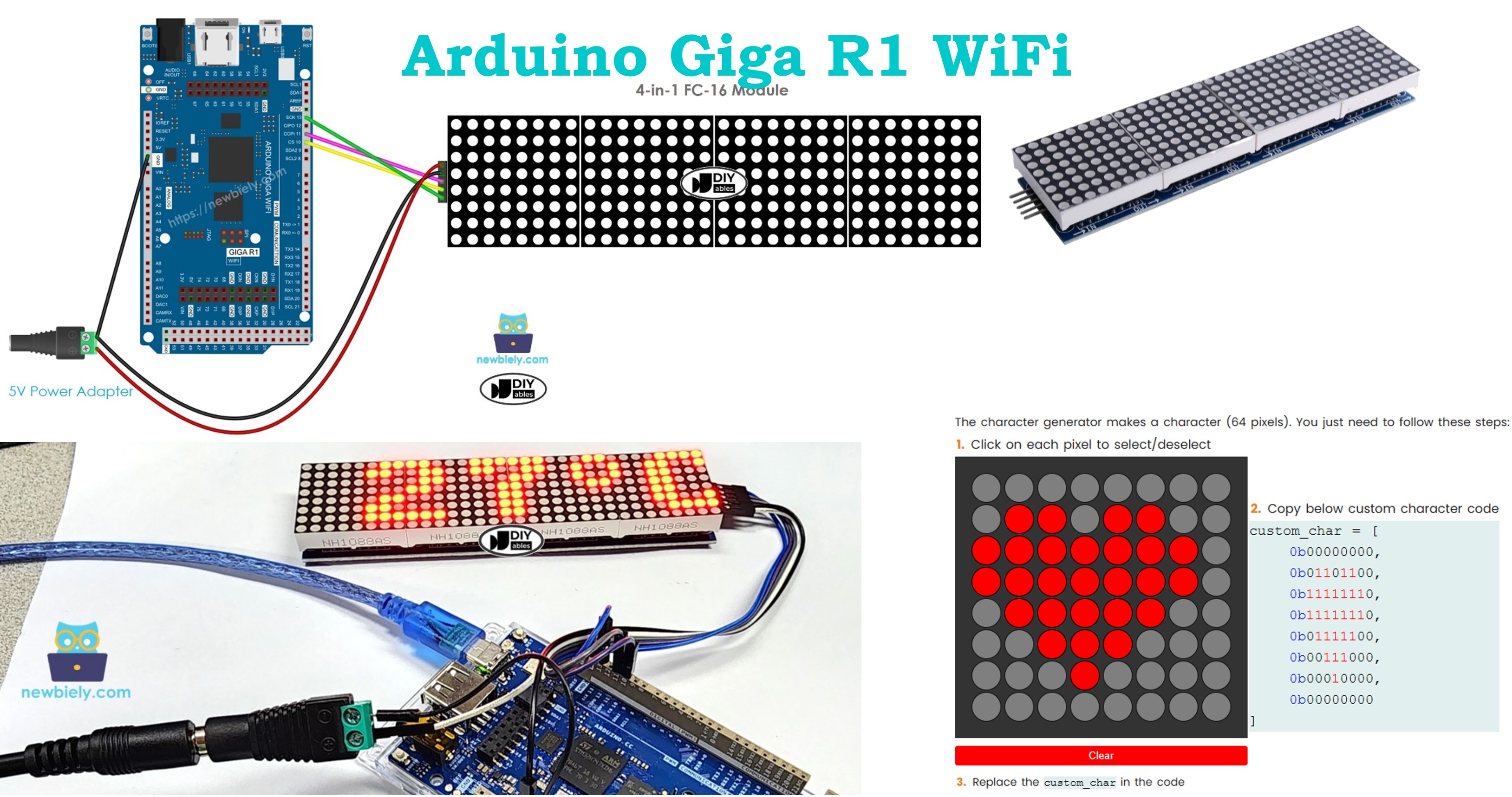
Arduino Giga R1 WiFi LED Matrix
This guide covers LED matrix display integration with the Arduino Giga R1 WiFi — from hardware setup to working code for text display and animations. The MAX7219-based LED matrix provides scalable dot matrix displays for digital signage, embedded systems, and IoT applications.
This tutorial demonstrates complete implementation for 8x8 single-block displays, 32x8 multi-block arrays, and custom daisy-chained configurations. You'll implement text display, scrolling animations, and brightness control using the MD_Parola library.
Hardware Preparation
Or you can buy the following kits:
| 1 | × | DIYables Sensor Kit (18 sensors/displays) |
Additionally, some of these links are for products from our own brand, DIYables .
Overview of LED Matrix
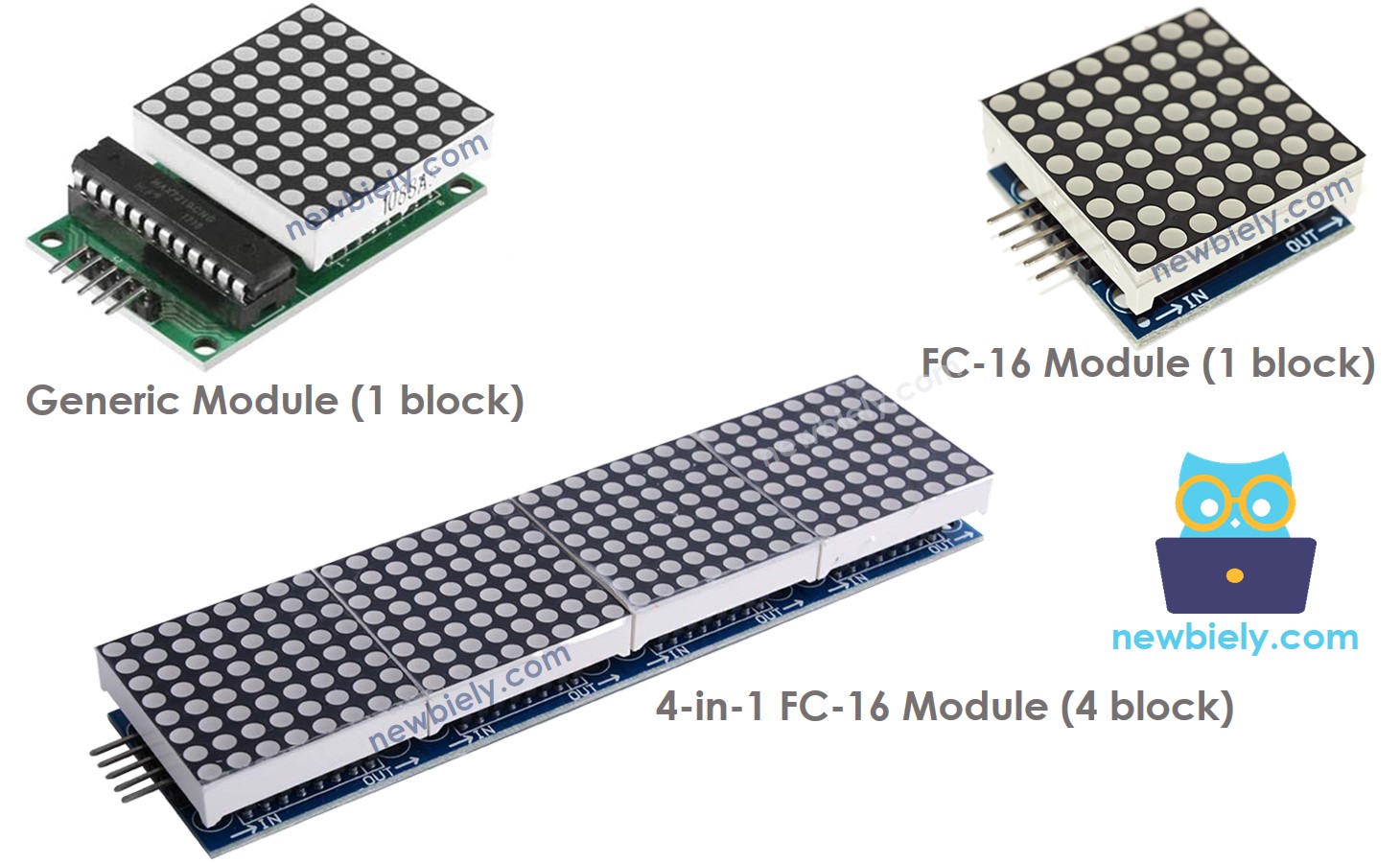
LED matrix displays are modular display systems designed for scalable text and graphics presentation. The MAX7219-based LED matrix represents the industry standard for Arduino-compatible dot matrix displays, offering integrated control circuitry and simplified serial communication protocols.
MAX7219-based LED matrix systems operate on a block-based architecture where each base unit contains an 8x8 LED array (64 individual LEDs) and a dedicated MAX7219 display driver. The MAX7219 controller handles LED multiplexing, brightness control (16 intensity levels), and SPI communication protocol implementation. This integration eliminates the need for external current-limiting resistors and complex timing control in the host microcontroller.
The system supports two primary module formats: generic modules with standard pin layouts, and FC-16 modules featuring more compact designs with different physical pin arrangements. Both formats maintain electrical compatibility and identical communication protocols. Multi-block displays achieve scalability through daisy-chain configuration, where each MAX7219 controller receives data, processes its assigned segment, and forwards remaining data to the next controller in the chain.
Key technical specifications include: 5V operating voltage, maximum 330mA current draw per block at full brightness, SPI communication at up to 10MHz, and cascading support for virtually unlimited display width. The MAX7219's built-in oscillator eliminates external timing components, while integrated current sources provide consistent LED brightness across the entire display matrix.
Integration with the Arduino Giga R1 WiFi leverages the board's hardware SPI controller (SPI1) for optimal performance. The Giga's 480MHz core frequency ensures smooth animation rendering and real-time display updates even with large multi-block configurations. Power considerations become critical with multi-block arrays — external 5V power supplies are mandatory for displays exceeding single-block configurations due to current requirements that exceed Arduino's onboard regulator capacity.
Pinout
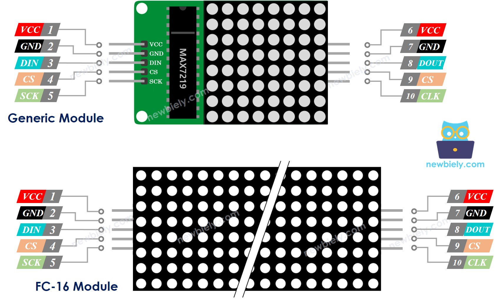
The pinout configuration determines the electrical interface between the Arduino Giga R1 WiFi and the LED matrix system. Correct wiring is essential — an incorrect power connection may damage the MAX7219 controller, while incorrect data connections will produce no display output or erratic behavior.
LED matrix blocks feature dual pin groups to support daisy-chain configurations. The input pin group receives control signals and power from the Arduino or previous block, while the output pin group forwards signals to subsequent blocks in the chain.
Input Pin Group:
- VCC: 5V power input, 3.3V tolerant but requires 5V for full brightness operation. Connects to external 5V supply or Arduino 5V pin (single block only). Current consumption: 50-330mA per block depending on brightness and active LEDs.
- GND: Ground reference. Connects to Arduino GND pin and external power supply ground.
- DIN: Serial data input, 5V/3.3V compatible. Connects to Arduino SPI MOSI pin (pin 11 on Giga R1 WiFi). Receives 16-bit control words at up to 10MHz SPI clock rate.
- CS: Chip Select (active low), 5V/3.3V compatible. Connects to any Arduino digital pin. Latches data from shift register to display output on rising edge.
- CLK: Serial clock input, 5V/3.3V compatible. Connects to Arduino SPI SCK pin (pin 13 on Giga R1 WiFi). Controls data transfer timing.
Output Pin Group:
- VCC: 5V power output to next block. Forward connection only, no additional current capacity.
- GND: Ground output to next block.
- DOUT: Serial data output. Connects to DIN of next block in daisy-chain configuration.
- CS: Chip Select output. Connects to CS of next block.
- CLK: Clock output. Connects to CLK of next block.
The Arduino Giga R1 WiFi's SPI1 peripheral (pins 11, 12, 13) provides hardware-accelerated communication with optimal timing precision. Pin 12 (MISO) remains unused in this configuration as LED matrices provide no return data path. Chip Select can utilize any digital pin, though pins with PWM capability offer no advantage in this application.
Wiring Diagram
The wiring configuration varies based on display architecture: single block, pre-built multi-block, or custom multi-block assembly. Power distribution becomes critical with multi-block displays due to cumulative current requirements approaching 1A at maximum brightness settings.
Electrical Note: The diagrams below show the minimum viable connections for development and testing. For production or extended use, consider adding 100µF electrolytic capacitors across power rails near each block to reduce switching noise and improve display stability. Ensure wire gauge supports current requirements — 22AWG minimum for single blocks, 18AWG recommended for multi-block power distribution.
Single Block Configuration:
Connect the input pin group to the Arduino Giga R1 WiFi while leaving output pins unconnected. This configuration suits applications requiring 8x8 displays such as status indicators, small message displays, or prototyping applications.
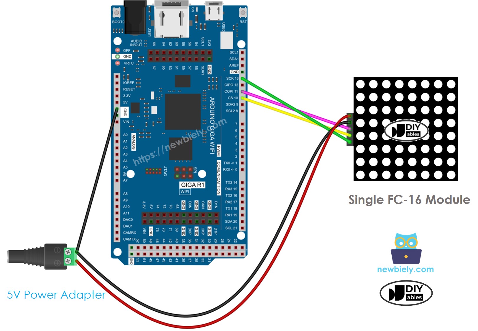
This image is created using Fritzing. Click to enlarge image
| FC-16 Module Pin | Arduino Giga R1 WiFi Pin | Function |
|---|---|---|
| VCC | External 5V Supply | Power Input |
| GND | GND + External Supply GND | Ground Reference |
| DIN | 11 (MOSI) | SPI Data |
| CS | 3 (Digital) | Chip Select |
| CLK | 13 (SCK) | SPI Clock |
Pre-built Multi-Block Configuration:
Factory-assembled multi-block displays include internal wiring between blocks. Connect only the input pin group to Arduino and external power supply while leaving output pins unconnected.
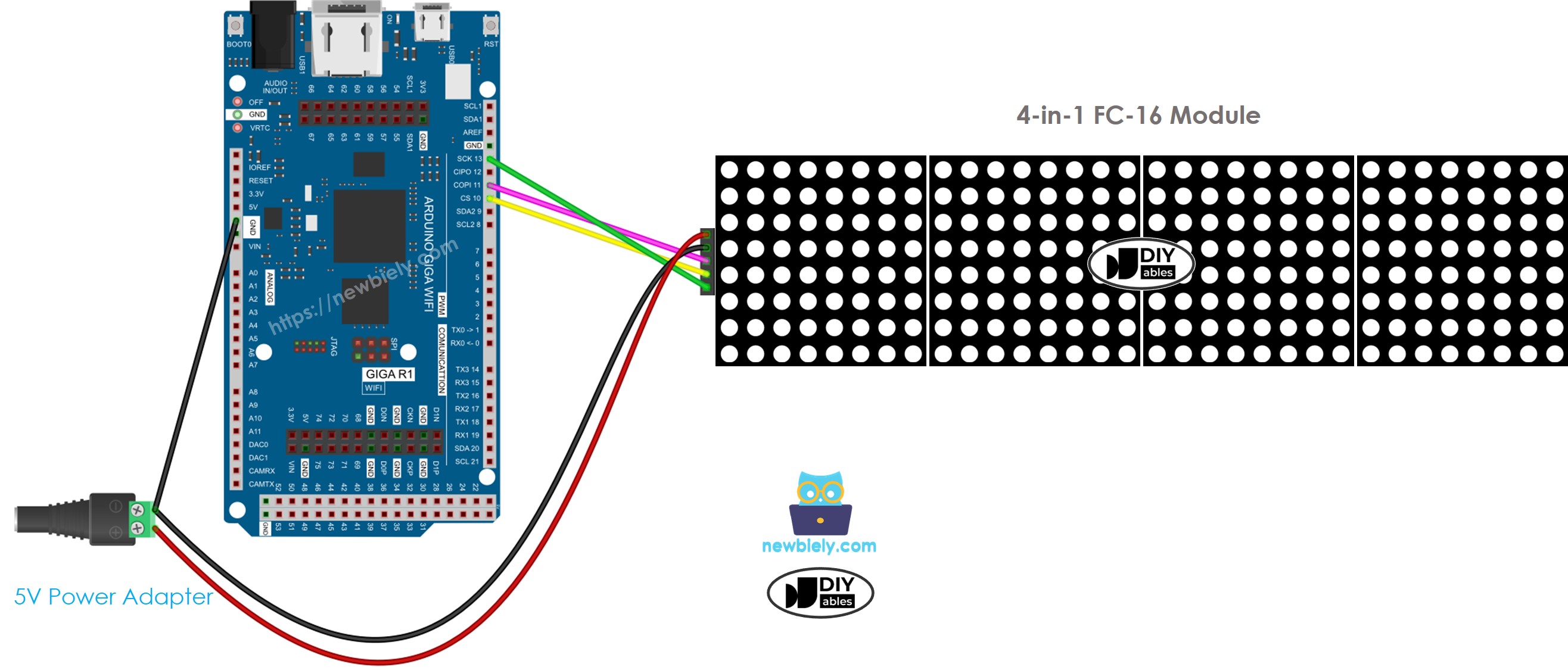
This image is created using Fritzing. Click to enlarge image
Custom Multi-Block Assembly:
Custom configurations require daisy-chain wiring where each block's output pins connect to the next block's input pins. The Arduino connects only to the first block's input pins, while the last block's output pins remain unconnected.
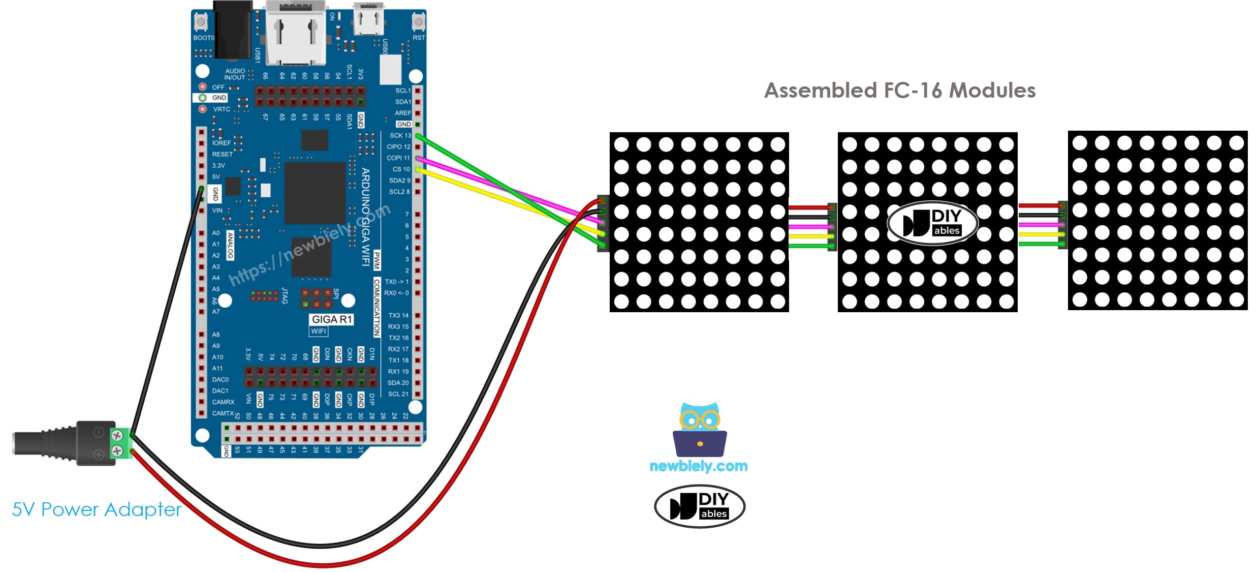
This image is created using Fritzing. Click to enlarge image
Critical Power Considerations:
Multi-block displays draw substantial current (up to 1A total) that exceeds Arduino's onboard regulator capacity. External 5V power supplies rated for display requirements are mandatory. Arduino and LED matrix can share power from a 5V adapter with adequate current capacity, typically 2A minimum for 4-block displays.
SPI Pin Requirements:
The Arduino Giga R1 WiFi's hardware SPI pins are fixed: pin 13 (SCK) and pin 11 (MOSI) must be used for optimal performance. The CS pin can connect to any digital pin and is specified in software configuration. Using hardware SPI ensures reliable communication timing and reduces CPU overhead compared to software SPI implementations.
How To Program For LED Matrix
LED matrix programming requires understanding the MAX7219 controller's register structure and communication protocol. The MD_Parola and MD_MAX72xx libraries abstract this complexity, providing high-level functions for text display, animation effects, and hardware management. The implementation follows a structured approach: hardware definition, library configuration, display initialization, and content management.
Library Architecture:
The MD_MAX72xx library provides low-level MAX7219 communication and hardware abstraction, handling SPI transactions, register configuration, and LED matrix control. MD_Parola builds upon this foundation, adding text rendering, animation effects, and font management. This layered approach enables both simple text display and complex custom graphics implementations.
Hardware Configuration Process:
Include the required libraries that provide MAX7219 communication and text display functionality:
Specify the hardware type to match your physical modules. This parameter configures internal timing and pin mapping algorithms:
Define the number of 8x8 blocks in your display configuration. A 32x8 display contains 4 blocks, while an 8x8 display uses 1 block:
Specify the digital pin connected to the CS (Chip Select) line. This pin controls when data transfers from the shift register to display outputs:
Create the display object instance with hardware parameters. This object manages all display operations and communication protocols:
Initialization Sequence:
The setup() function configures the display hardware and establishes initial display parameters:
The begin() function initializes SPI communication parameters, configures MAX7219 control registers for normal operation, and establishes the daisy-chain communication protocol for multi-block displays. Brightness control operates through PWM within each MAX7219, providing flicker-free intensity adjustment across the full 0-15 range.
Arduino - LED Matrix Code
The implementation demonstrates comprehensive LED matrix control including text display, scrolling effects, and brightness management. This code targets a 32x8 FC-16 LED matrix display (4 blocks) but adapts easily to other configurations by modifying the MAX_DEVICES and HARDWARE_TYPE parameters. The example showcases both static text display and animated scrolling functionality.
Detailed Instructions
For initial Arduino Giga R1 WiFi setup, refer to the Arduino Giga R1 WiFi Getting Started guide before proceeding.
- Assemble Hardware: Connect the Arduino Giga R1 WiFi to the LED matrix following the wiring diagrams above. Verify power connections use external 5V supply for multi-block displays. Double-check SPI pin connections — incorrect wiring will prevent display operation and may damage components.
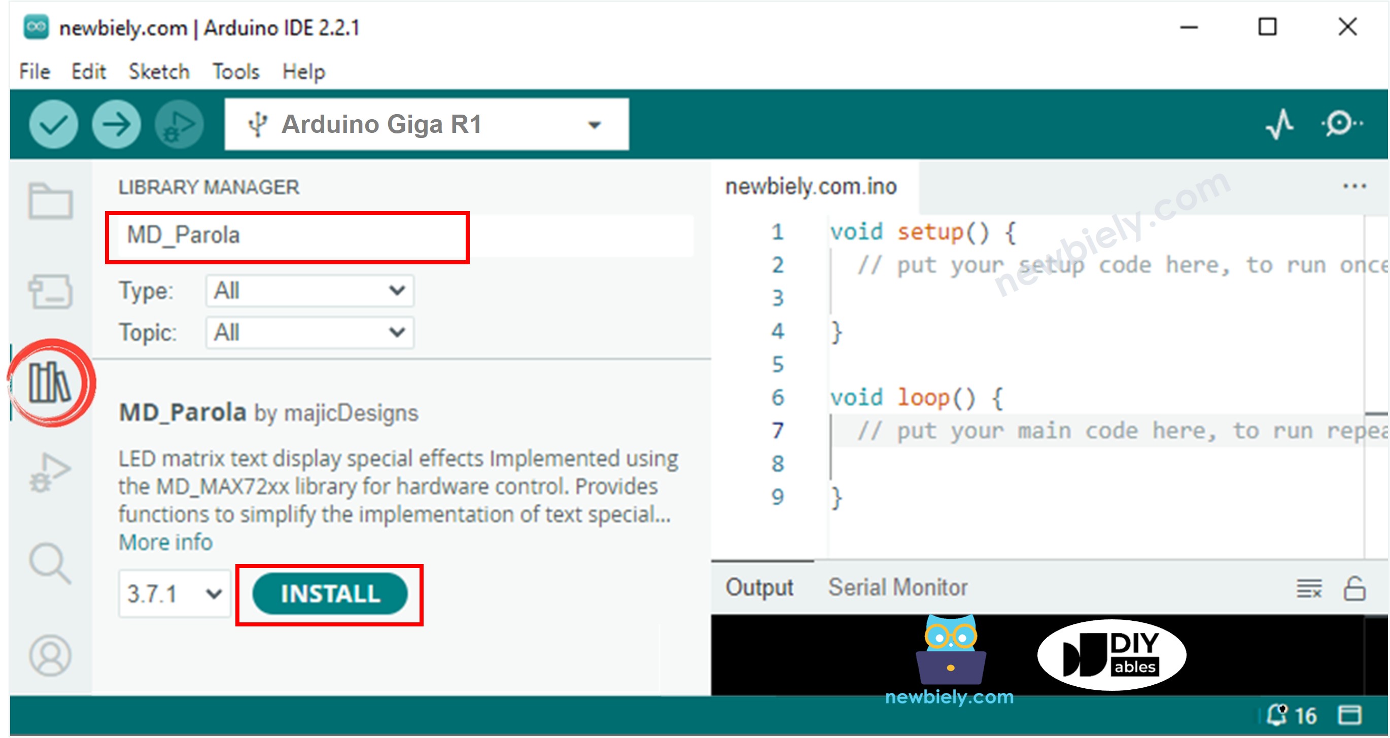
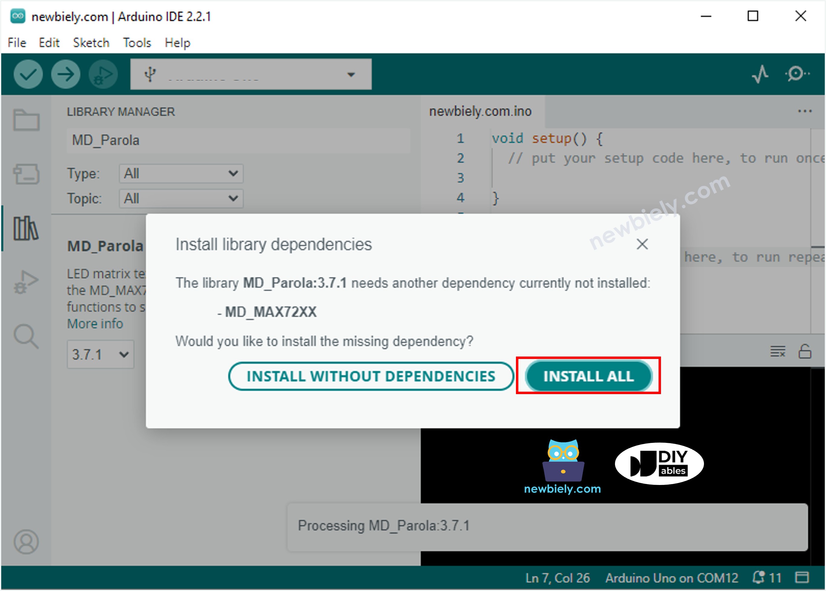
- Install Libraries: Navigate to the Libraries icon on the left bar of the Arduino IDE. Search "MD_Parola" and install the MD_Parola library. When prompted for dependencies, click "Install All" to include the required MD_MAX72XX library. These libraries provide MAX7219 communication protocols and text rendering functionality.
- Configure Library Dependencies: The installation process requires both MD_Parola (high-level text functions) and MD_MAX72XX (low-level hardware communication). The IDE will automatically resolve these dependencies during installation. Verify successful installation by checking that both libraries appear in the installed libraries list.
- Load Example Code: Copy the provided code and open it with Arduino IDE. Modify the HARDWARE_TYPE define to match your module type (FC16_HW or GENERIC_HW). Adjust MAX_DEVICES to reflect your display block count. Verify the CS_PIN setting matches your physical wiring.
- Upload and Test: Click Upload to compile and transfer code to the Arduino Giga R1 WiFi. The IDE will display compilation progress and upload status. Upon successful upload, the LED matrix should initialize and display the programmed content. If compilation fails, verify library installation and code syntax.
- Verify Operation: Observe the LED matrix display for expected text or animation output. The serial monitor provides debugging information if enabled in code. Incorrect display output typically indicates wiring errors, power supply issues, or hardware type mismatches. Adjust brightness using the setIntensity() function for optimal visibility.
Technical Note: The MD_Parola library supports extensive customization including custom fonts, animation timing control, and zone-based display management. For applications requiring real-time data display, consider implementing interrupt-driven data updates to maintain smooth animation while processing sensor inputs or network communication on the Giga R1 WiFi's second core.
Serial Monitor Output
Arduino LED Matrix Code – Scrolling Text
Extended messages that exceed display width require scrolling text techniques for complete visibility. The scrolling implementation uses the MD_Parola library's animation engine to create smooth horizontal text movement across the LED matrix. This approach enables displaying arbitrary-length messages on fixed-width displays while maintaining readability.
The scrolling algorithm operates by shifting display buffer contents at regular intervals, creating the visual effect of text movement. The Arduino Giga R1 WiFi's processing power enables smooth scrolling rates while maintaining responsive system operation for additional tasks such as sensor monitoring or network communication.
The scrolling implementation provides several configuration parameters: scroll direction (left, right, up, down), scroll speed (animation delay), and pause duration at message boundaries. The library handles character spacing, word boundaries, and display synchronization automatically. For applications requiring dynamic message updates, implement string manipulation functions that modify display content during runtime operation.
Advanced scrolling effects include fade-in/fade-out transitions, multi-zone displays with independent content, and synchronized scrolling across multiple display arrays. The MD_Parola library documentation provides comprehensive effect parameters and timing control functions for custom implementations.
For more text effects and animation options, please visit MD_Parola Library Reference.
Application Ideas
Industrial Status Display: Implement real-time production monitoring with scrolling status messages, error codes, and operational parameters. The Arduino Giga R1 WiFi's dual-core architecture enables simultaneous sensor data collection and display updates. Connect to industrial networks via Ethernet or WiFi for centralized monitoring integration.
IoT Information Panel: Create WiFi-connected information displays showing weather data, news feeds, or system notifications. Leverage the Giga R1 WiFi's built-in connectivity to fetch data from web APIs and display formatted content. The generous flash memory supports multiple font sets and extended message storage.
Embedded Debugging Interface: Deploy LED matrices as debugging displays for complex embedded systems. Display variable states, execution flow indicators, or error diagnostics in real-time. The high refresh rate capabilities enable monitoring fast-changing system parameters during development and testing phases.
Public Announcement System: Build scalable message displays for transportation, retail, or institutional environments. The modular LED matrix architecture supports displays from desktop-sized units to wall-mounted installations. Implement message scheduling, priority handling, and remote content management via the Giga R1 WiFi's network capabilities.
Educational Demonstration Tool: Create interactive displays for STEM education demonstrating concepts like digital communication, matrix mathematics, or animation principles. Students can modify display content through serial commands or web interfaces, observing immediate visual feedback from their programming efforts.
Data Logging Visualization: Combine LED matrix displays with data logging applications to show trending information, threshold alerts, or system health status. The Giga R1 WiFi's USB host capability enables direct connection to storage devices for historical data display and analysis.
Video Section
The accompanying video demonstrates the complete hardware assembly process and live code execution. It covers the critical wiring steps for both single and multi-block configurations, showing proper power distribution techniques and SPI connection verification. The video displays real-time serial monitor output alongside LED matrix operation, illustrating the relationship between code execution and visual display output.
Challenge Yourself
Challenge: Implement dynamic brightness control based on ambient light sensing. Connect a photoresistor to an analog input and automatically adjust LED matrix intensity using the setIntensity() function. This creates displays that remain visible in varying lighting conditions while conserving power in dark environments.
Challenge: Create a multi-zone display with independent message areas. Use the MD_Parola library's zone management functions to divide your LED matrix into separate regions displaying different content types — static headers, scrolling messages, and real-time data feeds. The Arduino Giga R1 WiFi's processing power enables smooth multi-zone updates.
Challenge: Develop a web-based message control interface utilizing the Giga R1 WiFi's WiFi capabilities. Implement a REST API that accepts message updates via HTTP requests, enabling remote content management through web browsers or mobile applications. Include message scheduling and priority queue functionality.
Challenge: Design a data visualization system that displays sensor readings as scrolling graphs or bar charts on the LED matrix. Implement rolling averages, threshold indicators, and trend analysis using the display as a real-time dashboard. Connect multiple sensors and cycle through different data presentations automatically.
Challenge: Build a complete notification system that integrates email monitoring, calendar events, and system alerts into a unified LED matrix display. Use the Giga R1 WiFi's dual-core architecture to handle network communication on one core while maintaining smooth display updates on the second core. Implement message categorization with different animation effects for various notification types.