Arduino Giga R1 WiFi Solenoid Lock
This guide covers solenoid lock control with the Arduino Giga R1 WiFi — from hardware setup to working code implementations. The solenoid lock, also known as the Electric Strike Lock, provides secure electronic locking for cabinets, drawers, doors, and access control systems.
The Arduino Giga R1 WiFi's dual-core architecture and extensive GPIO capabilities make it an excellent choice for security automation projects. This tutorial demonstrates complete solenoid lock integration, covering relay-based switching, power management, and both manual and automatic control modes. You'll implement two practical configurations: automated time-based locking and button-controlled access.
Solenoid locks require external power supplies (typically 12V, 24V, or 48V) and cannot be driven directly from microcontroller pins. This implementation uses a relay interface to handle the high-current switching safely. The Arduino Giga R1 WiFi's generous memory and processing power enable sophisticated access control logic, data logging, and network connectivity for IoT security applications.
This documentation covers the complete implementation process: understanding solenoid lock operation principles, relay interface design, safe wiring practices, and two progressively complex code examples. By the end, you'll have a working electronic lock system ready for integration into larger security projects.
Hardware Preparation
Or you can buy the following kits:
| 1 | × | DIYables Sensor Kit (18 sensors/displays) |
Additionally, some of these links are for products from our own brand, DIYables .
Overview of Solenoid Lock
Solenoid locks are electromagnetic actuators designed for secure access control applications. These devices use electromagnetic force to extend or retract a locking mechanism, providing reliable electronic control over physical security barriers. The underlying operating principle involves an electromagnetic coil that, when energized, generates a magnetic field to actuate the locking tongue through the controlled movement of a ferromagnetic core.
These locks operate on higher voltages than typical microcontroller logic levels, commonly requiring 12V, 24V, or 48V DC power supplies with current consumption ranging from 0.5A to 2A depending on the lock size and holding force requirements. The electromagnetic design provides rapid actuation (typically 50-200ms response time) and maintains secure locking under mechanical stress.
Solenoid locks offer several advantages over traditional mechanical locks: remote operation capability, integration with electronic access control systems, audit trail possibilities, and fail-safe or fail-secure operation modes. They're commonly deployed in commercial buildings, residential security systems, cabinet locks, and industrial access control where electronic oversight is required.
Integration with the Arduino Giga R1 WiFi requires careful consideration of power supply isolation, relay switching characteristics, and GPIO resource allocation. The high-current electromagnetic operation necessitates proper electrical isolation to prevent damage to the microcontroller's sensitive digital circuits.
An alternative to the solenoid lock is the electromagnetic lock, which operates on similar electromagnetic principles but with different mechanical implementations. You can learn more in Arduino - Electromagnetic Lock tutorial.
Pinout
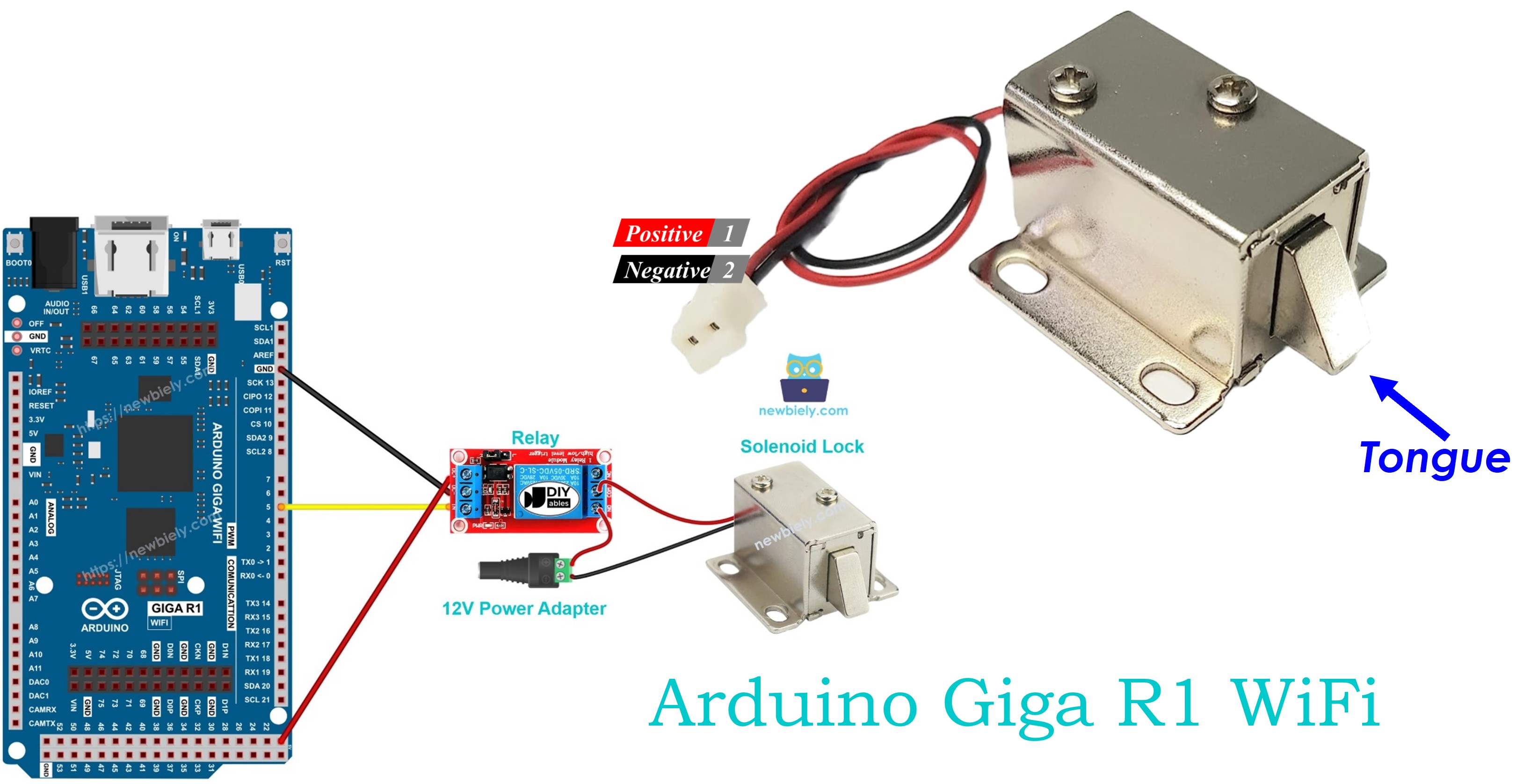
The pinout defines the electrical interface between the solenoid lock and the power supply circuit. Correct wiring is essential — incorrect polarity or voltage levels may damage the lock mechanism or create unreliable operation.
Solenoid locks include two primary electrical connections:
- Positive (+) wire (red): DC power input, typically red wire. Connects to positive terminal of 12V/24V/48V DC power supply to energize the electromagnetic coil. Current consumption varies from 0.5A to 2A depending on lock specifications.
- Negative (-) wire (black): Ground return path, typically black wire. Connects to negative terminal (GND) of DC power supply to complete the electromagnetic circuit. Must handle full operating current without voltage drop.

Electrical Note: Verify the voltage rating printed on the lock housing before connecting power. Applying incorrect voltage may result in insufficient holding force (undervoltage) or coil damage (overvoltage). Most consumer-grade solenoid locks operate at 12V DC with 1-2A current draw.
How It Works
The solenoid lock operates through electromagnetic field control of a spring-loaded locking mechanism. Understanding this operation is crucial for proper system integration and troubleshooting.
- Energized State (Powered): When DC voltage is applied across the coil terminals, current flows through the electromagnetic winding, creating a magnetic field. This field attracts the ferromagnetic locking tongue (strike), extending it against spring tension. The extended position engages the door frame or latch mechanism, securing the lock in the closed position. The electromagnetic holding force typically ranges from 100-500 pounds depending on lock specifications.
- De-energized State (Unpowered): When power is removed, the electromagnetic field collapses immediately. The spring mechanism retracts the locking tongue to its default position, allowing the door to open freely. This creates a fail-safe operation mode where power loss results in unlocked access.
Operating Characteristics: Response time is typically 50-200ms for both lock and unlock operations. The lock maintains position as long as power is applied, consuming continuous current. Some designs include LED indicators or auxiliary contacts for position feedback.
※ NOTE THAT:
The solenoid lock usually uses 12V, 24V or 48V power supply. Therefore, we CANNOT connect the solenoid lock directly to Arduino pin. We have to connect it to Arduino pin via a relay
Relay Interface Configuration: When connecting the solenoid lock through a relay in normally open mode:
- Relay Open (Arduino LOW): No current path to solenoid lock coil. Lock tongue retracts due to spring tension. Door state: unlocked.
- Relay Closed (Arduino HIGH): Current flows from power supply through relay contacts to solenoid lock coil. Electromagnetic field extends lock tongue. Door state: locked.
By controlling the relay coil through an Arduino GPIO pin, the microcontroller can precisely control lock timing, implement access control logic, and integrate with sensors or network commands. The relay provides complete electrical isolation between the Arduino's 3.3V logic levels and the solenoid lock's high-voltage, high-current requirements.
Learn more about relay operation principles and Arduino integration in Arduino - Relay tutorial.
Wiring Diagram
The wiring implementation demonstrates relay-based switching to control the solenoid lock safely from the Arduino Giga R1 WiFi. This configuration provides proper electrical isolation and current handling for the electromagnetic lock mechanism.
Electrical Note: The diagram above shows the minimum viable connection for development and testing. For production or extended use, consider adding a flyback diode across the solenoid lock terminals to suppress electromagnetic interference, and ensure the relay contact rating exceeds the lock's maximum current draw by at least 25%.
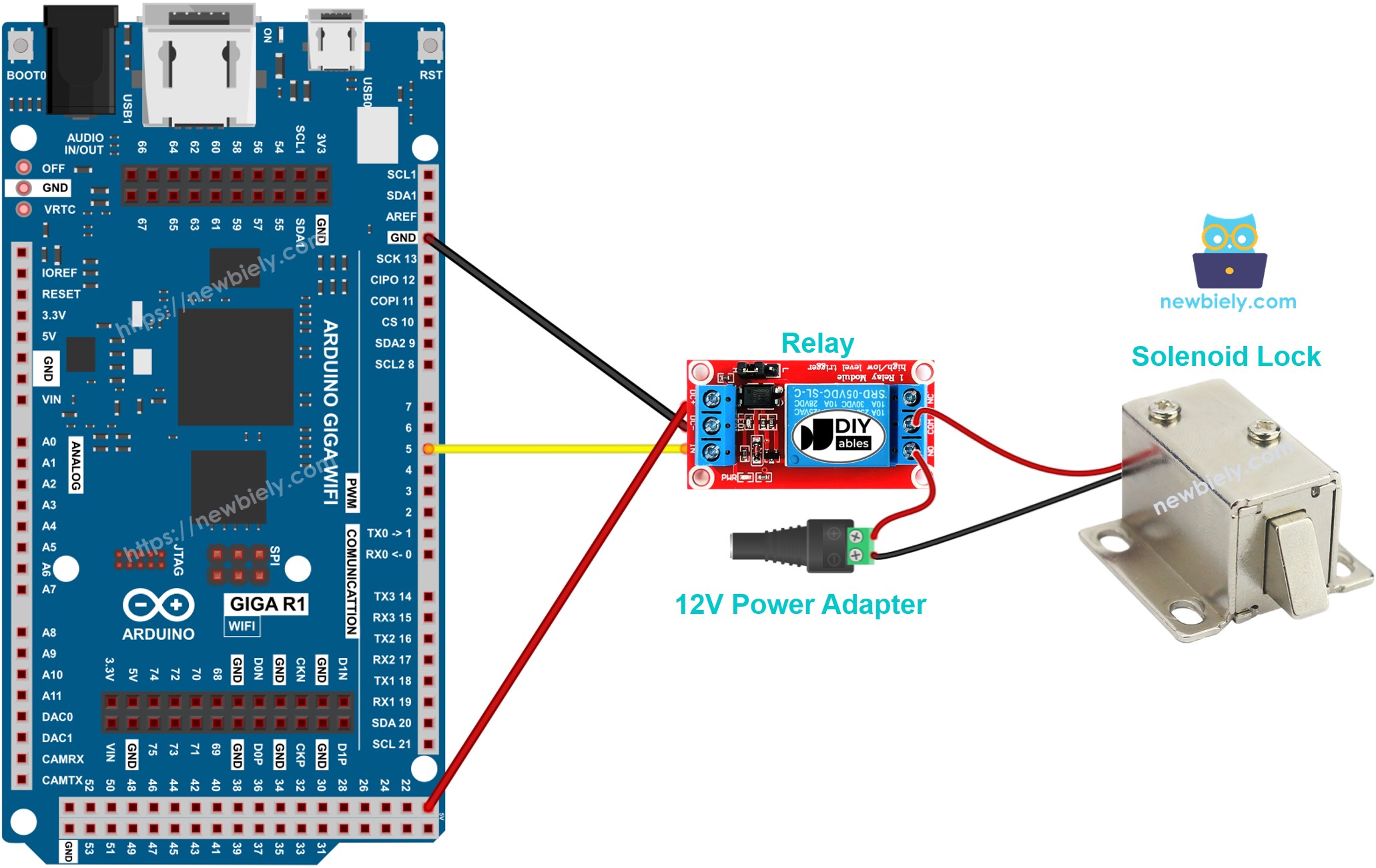
This image is created using Fritzing. Click to enlarge image
Power Supply Requirements: The 12V adapter must provide sufficient current capacity for the solenoid lock's operating requirements (typically 1-2A continuous). The DC power jack creates a convenient connection point for the external power supply while maintaining proper isolation from the Arduino's USB power domain.
| Component Pin | Arduino Giga R1 WiFi Pin |
|---|---|
| Relay VCC | 5V |
| Relay GND | GND |
| Relay IN | Digital Pin 3 |
| Solenoid Lock (+) | 12V Power Supply (+) |
| Solenoid Lock (-) | Relay NO Contact |
| 12V Power Supply (-) | Relay NO Contact Common |
Safety Considerations: Ensure all connections are secure before applying power. Loose connections in the high-current solenoid circuit may cause arcing or overheating. Verify relay specifications match or exceed the solenoid lock's current requirements.
Arduino Code
The following implementation demonstrates time-based solenoid lock control using digital GPIO output. The code is structured to handle relay switching with clear timing intervals for demonstration purposes. The lock/unlock cycle operates on a 5-second interval to showcase both locked and unlocked states.
The relay control logic uses direct digital output to pin 3, which connects to the relay's control input. When the Arduino outputs HIGH (3.3V), the relay coil energizes, closing the normally open contacts and completing the circuit to power the solenoid lock. The solenoid lock control implementation abstracts the relay switching into clear lock() and unlock() functions for maintainable code structure.
The below code lock/unlock the door every 5 seconds:
Detailed Instructions
For initial Arduino Giga R1 WiFi setup, refer to the Arduino Giga R1 WiFi Getting Started guide before proceeding.
- Connect Hardware: Wire the solenoid lock, relay, and power supply according to the wiring diagram. Verify all connections are secure and polarity is correct before applying power.
- Open Arduino IDE: Launch the Arduino IDE and ensure the Arduino Giga R1 WiFi board is selected from the Tools > Board menu.
- Copy Code: Copy the above code and paste it into a new Arduino IDE sketch window.
- Upload Code: Click the Upload button to compile and transfer the code to the Arduino Giga R1 WiFi. The compilation should complete without errors.
- Observe Operation: Watch the solenoid lock mechanism. The lock tongue should extend for 5 seconds (locked), then retract for 5 seconds (unlocked) in a continuous cycle.
- Monitor Serial Output: Open the Serial Monitor at 9600 baud to see the lock state messages and verify proper timing.
- Verify Power Supply: Confirm the 12V power adapter provides stable voltage and the relay switching operates without voltage drops.
Technical Note: The delay() function blocks program execution during timing intervals. For applications requiring concurrent operations or interrupt handling, consider implementing non-blocking timing using millis() for more sophisticated control logic.
Serial Monitor Output
Application Ideas
Security Access Control System: Implement a comprehensive door access system using RFID cards or keypads. The Arduino Giga R1 WiFi's dual-core processing enables simultaneous user authentication and network logging, while the built-in WiFi capability allows remote monitoring and control through web interfaces or mobile applications.
Industrial Equipment Safety Lockout: Deploy the solenoid lock for machinery safety systems where equipment must be physically secured during maintenance. The Arduino's reliable GPIO control ensures consistent lock operation, while digital inputs can monitor safety switches and emergency stops for integrated protection.
Smart Cabinet and Storage Management: Create intelligent storage solutions for laboratories, pharmacies, or secure document storage. The Arduino Giga R1 WiFi's memory capacity supports extensive access logging, user management databases, and network integration with inventory management systems.
Automated Parking or Gate Control: Build vehicle access control systems where the solenoid lock secures gate mechanisms or parking barriers. The dual-core architecture handles sensor processing for vehicle detection while managing lock timing and network communications for remote operation.
Time-Based Access Control: Implement schedule-based locking systems for offices, server rooms, or restricted areas. The Arduino Giga R1 WiFi's real-time capabilities support complex scheduling logic, while WiFi connectivity enables synchronization with network time servers and centralized management systems.
IoT Security Monitoring Platform: Develop a connected security system that logs all access attempts, sends notifications via WiFi, and provides remote control through web APIs. The Arduino's processing power supports encryption, secure communications, and local data buffering for reliable operation.
Video Section
The accompanying video demonstrates the complete hardware assembly process and live code execution. It covers proper relay wiring techniques, power supply connections, and safety considerations in detail. The demonstration shows both automatic timing operation and manual button control modes, with clear views of the lock mechanism operation and expected serial monitor output.
Challenge Yourself
Challenge: Implement access logging with timestamps to track all lock/unlock events. Use the Arduino Giga R1 WiFi's built-in RTC functionality to maintain accurate timing and store event logs in EEPROM for persistence across power cycles.
Challenge: Add RFID card authentication to the button control system. Integrate an RFID reader module and implement a card database using the Arduino's expanded memory, allowing multiple authorized users with individual access logging and permission levels.
Challenge: Create a WiFi-based remote control interface using the Arduino Giga R1 WiFi's network capabilities. Implement a simple web server that serves a control page, handles authentication, and provides real-time lock status updates through HTTP requests.
Challenge: Design a fail-safe power backup system using a battery and voltage monitoring. Implement low-power modes during battery operation and emergency unlock procedures when backup power reaches critical levels, ensuring safe operation during power outages.
Challenge: Build a comprehensive security system that integrates motion detection, door position sensing, and unauthorized access alerts. Use the Arduino's dual-core architecture to handle multiple sensors simultaneously while maintaining responsive lock control and network communications.