Arduino Giga R1 WiFi Potentiometer
This guide covers potentiometer interfacing with the Arduino Giga R1 WiFi — from hardware setup to working code for analog voltage control applications. The rotary potentiometer serves as a fundamental analog input sensor for position sensing, user interface controls, and variable voltage generation in embedded systems.
The Arduino Giga R1 WiFi's high-resolution 12-bit ADC capability provides superior analog signal processing compared to standard Arduino boards, enabling more precise potentiometer readings with 4096 discrete values instead of the typical 1024. This enhanced resolution is particularly valuable for applications requiring fine-grained control such as motor positioning, audio volume control, or sensor calibration systems.
Potentiometers are widely deployed across industrial automation, consumer electronics, and prototyping applications. Common implementations include servo motor position feedback, LED brightness control, variable speed motor drives, and manual parameter adjustment interfaces. The combination of the Arduino Giga R1 WiFi's processing power and analog input precision makes it ideal for developing sophisticated control systems that require real-time analog signal processing.
This tutorial walks through the complete implementation process: understanding potentiometer operating principles, establishing proper electrical connections, implementing analog-to-digital conversion code, and scaling raw ADC values to meaningful control parameters. You'll implement working examples that demonstrate both basic voltage measurement and practical control applications using the Arduino Giga R1 WiFi platform.
Hardware Preparation
Or you can buy the following kits:
| 1 | × | DIYables Sensor Kit (18 sensors/displays) |
Additionally, some of these links are for products from our own brand, DIYables .
Overview of Potentiometer
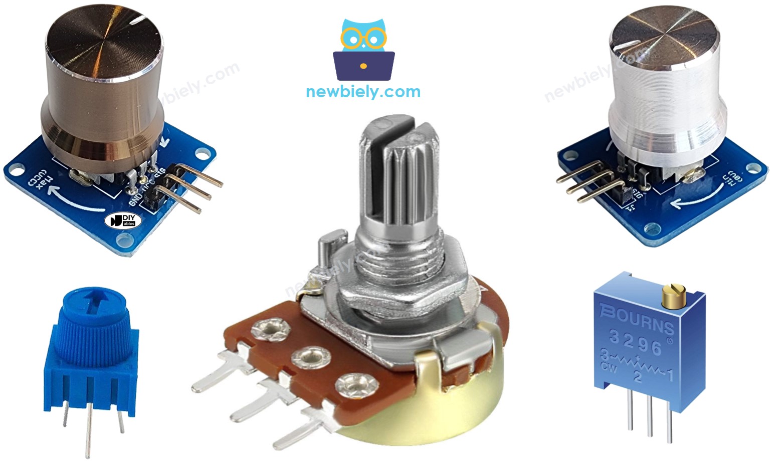
A rotary potentiometer is a three-terminal variable resistor designed for manual analog control applications. The device functions as a voltage divider, providing a continuously variable output voltage proportional to the shaft rotation angle. Potentiometers are essential components in user interface design, offering tactile feedback for parameter adjustment in audio equipment, instrumentation, and control systems.
Technical specifications for standard rotary potentiometers include resistance values ranging from 1KΩ to 1MΩ, with common values of 10KΩ suitable for Arduino analog input applications. The device operates across the full supply voltage range, typically 3.3V to 5V in microcontroller circuits, with linearity specifications of ±0.5% for precision applications. Power dissipation ratings typically range from 0.1W to 0.5W for standard through-hole components.
The underlying operating principle relies on a resistive track with a movable wiper contact. As the shaft rotates, the wiper traverses the resistive element, creating two variable resistances in series between the outer terminals. This configuration generates an output voltage that varies linearly with angular position, making it ideal for position sensing and manual control applications.
Integration with the Arduino Giga R1 WiFi leverages the microcontroller's enhanced analog input capabilities. The board's improved ADC resolution and lower noise characteristics enable more precise potentiometer readings compared to standard Arduino implementations. Multiple analog input pins (A0-A7) allow simultaneous monitoring of several potentiometers for multi-axis control applications.
Compared to alternative position sensors such as rotary encoders or hall-effect sensors, potentiometers provide absolute position feedback without requiring complex decoding logic. However, they are subject to mechanical wear and contact resistance variations over extended use cycles, making them more suitable for manual adjustment rather than continuous automated positioning applications.
Pinout
The potentiometer pinout configuration determines proper electrical integration with the Arduino Giga R1 WiFi analog input system. Correct wiring is essential — an incorrect connection may damage the component or produce unreliable readings due to improper voltage reference levels.
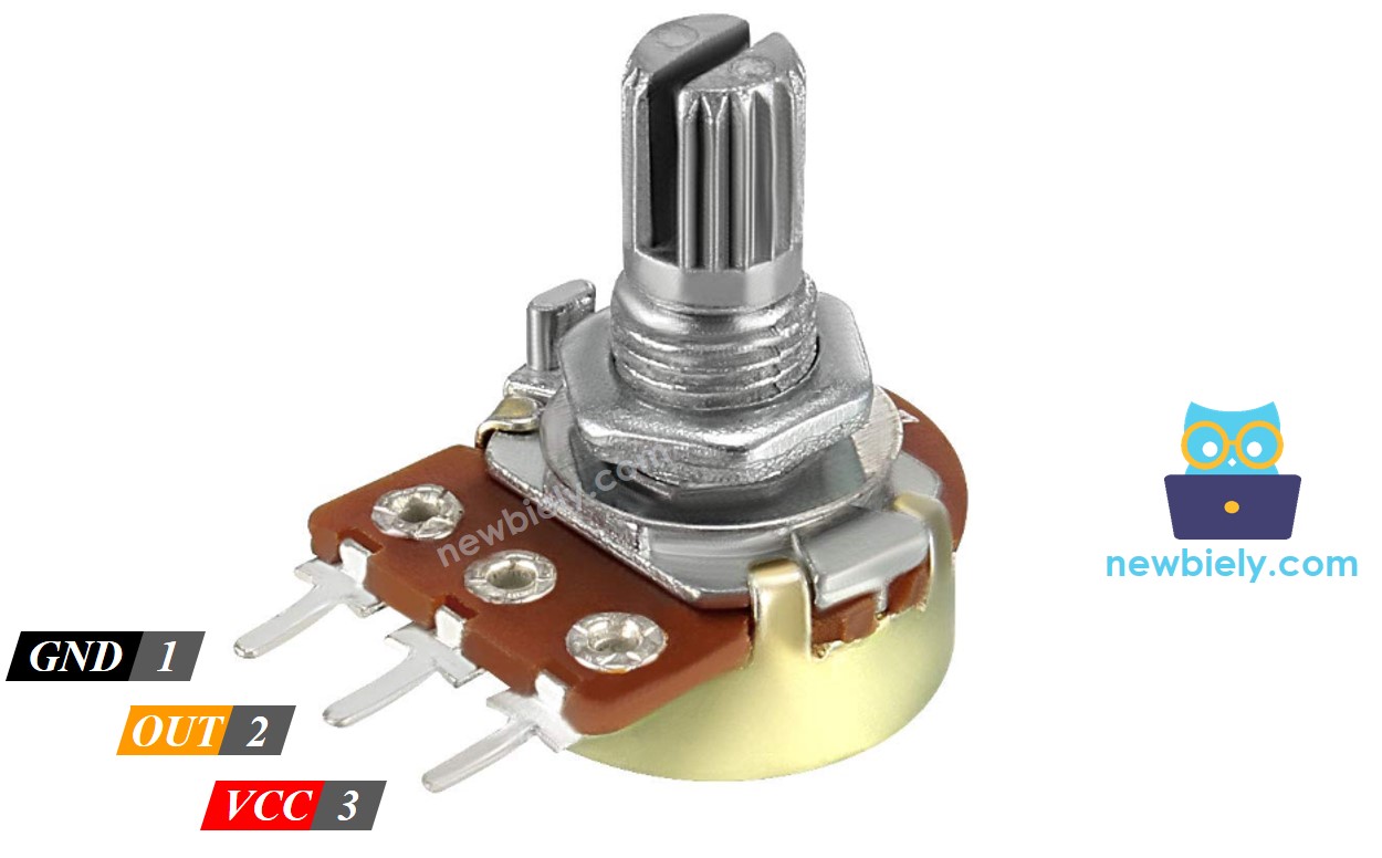
Potentiometer terminals are configured as follows:
- GND pin: Ground reference terminal (0V). Connects to Arduino Giga R1 WiFi GND pin to establish common voltage reference. This terminal handles return current path for the voltage divider circuit.
- VCC pin: Positive supply terminal (+3.3V or +5V). Connects to Arduino power rail to provide voltage divider reference. Current consumption is minimal, typically under 1mA for 10KΩ potentiometers.
- Output pin: Variable voltage output (0V to VCC). Connects to Arduino analog input (A0-A7) to provide position-proportional voltage signal. Output impedance varies from 0Ω to full resistance value depending on wiper position.
Signal characteristics include output voltage swing from 0V to supply voltage with linear relationship to shaft angle. The output pin provides low-current drive capability, requiring high-impedance loads such as Arduino analog input pins (typically >10MΩ input impedance). Pull-up or pull-down resistors are not required as the potentiometer provides active voltage division.
Arduino Giga R1 WiFi analog input pins accept 0-3.3V signals when powered from 3.3V, or 0-5V when using 5V supply. The enhanced ADC resolution provides 4096 discrete levels (12-bit) compared to 1024 levels (10-bit) on standard Arduino boards, enabling more precise position detection and smoother control response.
※ NOTE THAT:
GND pin and VCC pin are interchangeable. The voltage value at the output pin is inverted when these pins are swapped — minimum rotation produces maximum voltage output.
How It Works
The potentiometer operates as a variable voltage divider using a resistive track and movable wiper contact mechanism. The shaft rotation range spans from 0° to ANGLE_MAX (typically 270° to 330° depending on manufacturer specifications), with the wiper contact traversing the resistive element to create proportional voltage division.
Output voltage relationship follows the linear equation: output_voltage = (rotation_angle × VCC) / ANGLE_MAX. At 0° rotation, the wiper contacts the ground-connected terminal, producing 0V output. At maximum rotation (ANGLE_MAX), the wiper approaches the VCC terminal, generating output voltage equal to supply voltage. Intermediate positions produce proportionally scaled voltages with linearity typically within ±0.5%.
The resistive track construction uses carbon composition or cermet materials to provide stable electrical characteristics across temperature and humidity variations. Contact resistance between wiper and track typically ranges from 1Ω to 10Ω, introducing minimal error in high-impedance analog input applications. Mechanical life expectancy exceeds 10,000 rotation cycles for standard components.
※ NOTE THAT:
ANGLE_MAX value depends on manufacturer specifications and mechanical construction. Most applications focus on relative position rather than absolute angle measurement, eliminating the need to determine precise ANGLE_MAX values for control purposes.
Arduino - Rotary Potentiometer Integration
The Arduino Giga R1 WiFi provides eight analog input channels (A0-A7) with enhanced 12-bit ADC resolution for precise potentiometer interface applications. Each analog input pin converts the applied voltage (0V to VREF) into discrete integer values ranging from 0 to 4095, providing superior resolution compared to standard 10-bit Arduino implementations.
The ADC conversion process samples the potentiometer output voltage and quantizes it using the microcontroller's internal voltage reference. The Arduino Giga R1 WiFi supports both 3.3V and 5V analog reference voltages, with the reference selection determining the full-scale input range. Using 5V reference provides maximum dynamic range for potentiometer applications, while 3.3V reference offers compatibility with modern low-voltage sensors and peripherals.
Raw ADC values require scaling to extract meaningful control parameters. The analogRead() function returns integer values from 0 to 4095 (12-bit resolution) on the Arduino Giga R1 WiFi, compared to 0 to 1023 on standard Arduino boards. This enhanced resolution enables smoother control response and reduced quantization noise in precision applications.
Common scaling applications include:
- Angular position calculation: Converting ADC values to shaft rotation angle in degrees
- Voltage measurement: Scaling ADC values to actual voltage present at potentiometer output
- Control parameter generation: Mapping potentiometer position to application-specific values (motor speed, LED brightness, servo position)
The Arduino Giga R1 WiFi's dual-core architecture enables real-time analog signal processing while maintaining responsiveness for communication and control tasks, making it ideal for applications requiring simultaneous potentiometer monitoring and system control functions.
Use Cases
Potentiometer applications with Arduino Giga R1 WiFi span multiple domains:
- Position feedback systems: Rescaling ADC values to angular position for mechanical control applications
- Voltage measurement: Converting digital readings to analog voltage values for instrumentation and calibration
- Parameter control: Mapping potentiometer position to controllable values such as motor speed, audio volume, or display brightness — representing the most common implementation pattern
Rescale Range Relationships
| Parameter | User Control | Minimum Value | Maximum Value |
|---|---|---|---|
| Rotation Angle | Manual shaft positioning | 0° | ANGLE_MAX (270°-330°) |
| Output Voltage | Potentiometer terminal voltage | 0V | VCC (3.3V or 5V) |
| ADC Reading | Arduino analogRead() result | 0 | 4095 (12-bit resolution) |
| Control Value | Application-specific scaling | VALUE_MIN | VALUE_MAX |
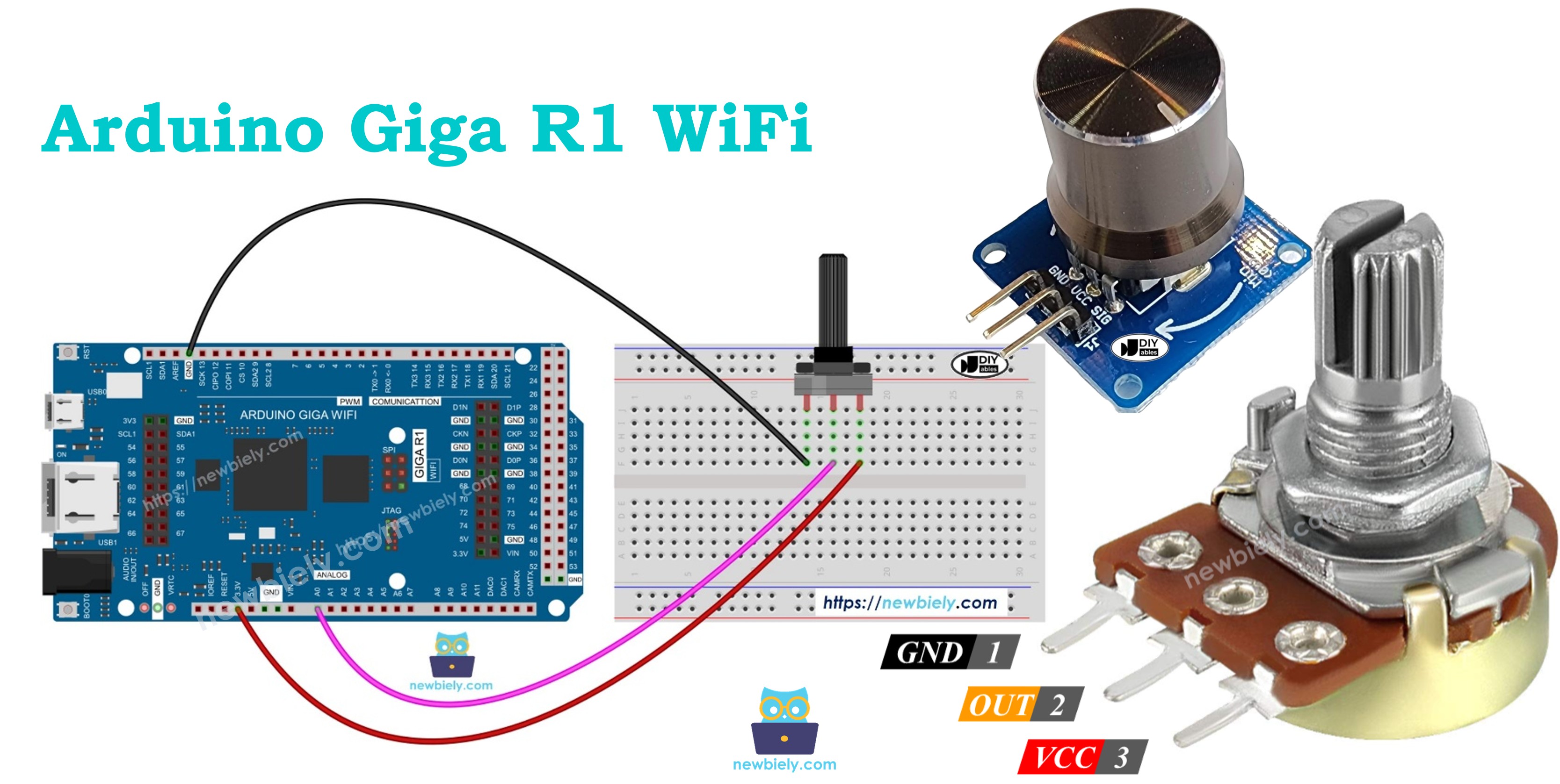
Wiring Diagram
The wiring diagram illustrates the essential connections between the rotary potentiometer and Arduino Giga R1 WiFi for analog signal acquisition. This configuration provides the minimum viable connection for basic potentiometer interfacing and ADC value monitoring.
Electrical Note: The diagram above shows the minimum viable connection for development and prototyping. For production or extended use, consider adding a 0.1µF ceramic capacitor between VCC and GND near the potentiometer to reduce noise and improve signal stability. Long wire connections may introduce electromagnetic interference — keep analog signal wires short and route away from digital switching signals.
Power supply considerations include the potentiometer's minimal current consumption (typically <1mA for 10KΩ devices) and the Arduino Giga R1 WiFi's ability to supply adequate current through its 5V and 3.3V power pins. The analog input presents high impedance (>10MΩ), ensuring minimal loading effects on the potentiometer output voltage.
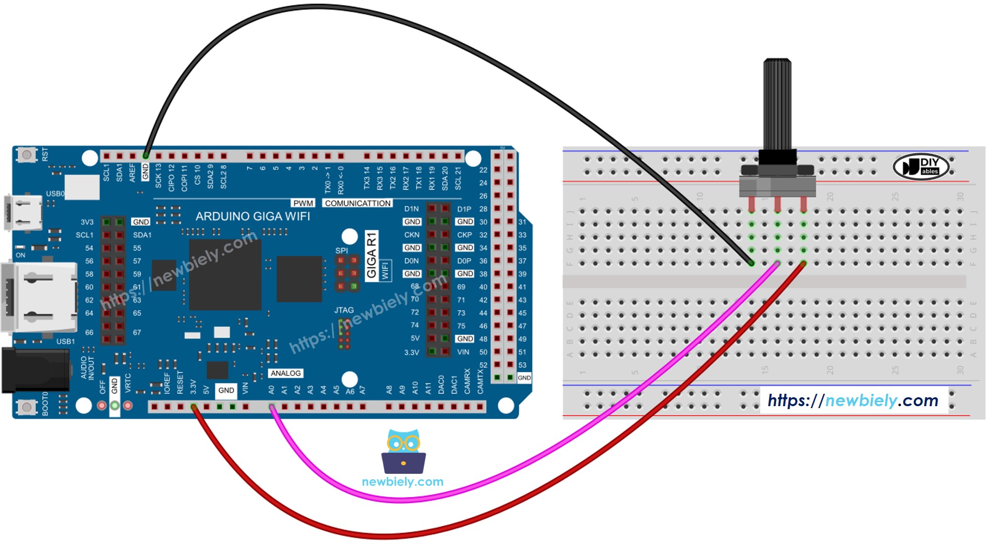
This image is created using Fritzing. Click to enlarge image
| Potentiometer Pin | Arduino Giga R1 WiFi Pin |
|---|---|
| GND | GND |
| VCC | 5V |
| Output | A0 (Analog Input) |
How To Program For Potentiometer
The following implementation demonstrates analog-to-digital conversion and data scaling techniques for potentiometer interfacing. The code is structured to handle real-time analog signal acquisition and provides flexible scaling options for various control applications. Key sections include ADC reading, voltage conversion, and custom scaling functions for floating-point calculations.
The analogRead() function interfaces with the Arduino Giga R1 WiFi's enhanced 12-bit ADC system, providing superior resolution compared to standard Arduino implementations. The map() function handles integer scaling operations, while custom floating-point scaling functions enable precision voltage and parameter calculations.
Programming steps include:
- Read analog value from the potentiometer-connected input pin using analogRead() function:
- Scale to angular position using map() function for integer degree calculations:
- Convert to voltage measurement for instrumentation applications:
- Generate control parameters by scaling to application-specific ranges (motor speed, brightness, servo position):
- LED brightness control example demonstrates PWM value generation from potentiometer input. LED brightness control requires PWM values from 0 (OFF) to 255 (maximum brightness):
- Custom brightness range enables nightlight-to-bright scaling for specific lighting applications:
※ NOTE THAT:
The map() function handles integer scaling for int and long data types. For floating-point control values, implement the floatMap() function to maintain precision in voltage measurements and proportional control calculations.
Floating-point scaling function for precision applications:
Arduino Code
The implementation below demonstrates potentiometer interfacing with voltage measurement capabilities. This example showcases both ADC value acquisition and floating-point voltage conversion, providing a foundation for control system development using the Arduino Giga R1 WiFi's enhanced analog input features.
Detailed Instructions
For initial Arduino Giga R1 WiFi setup, refer to the Arduino Giga R1 WiFi Getting Started guide before proceeding with potentiometer implementation.
- Connect Components: Wire the potentiometer to Arduino Giga R1 WiFi according to the wiring diagram above. Verify connections: GND to GND, VCC to 5V, and output to analog pin A0. Incorrect wiring may produce erratic readings or no response.
- Open Arduino IDE: Launch the Arduino IDE and verify the Arduino Giga R1 WiFi board is selected in Tools > Board menu. Ensure the correct COM port is selected for USB communication.
- Copy and Load Code: Copy the complete code example above into a new Arduino IDE sketch. The code includes both ADC reading and floating-point voltage conversion functions.
- Upload Program: Click the Upload button to compile and transfer the code to the Arduino Giga R1 WiFi. Monitor the IDE console for compilation errors or upload failures. Successful upload displays "Done uploading" message.
- Open Serial Monitor: Launch Tools > Serial Monitor and set baud rate to 9600 to match the Serial.begin() configuration. The monitor should display continuous analog readings and voltage calculations.
- Test Potentiometer Response: Rotate the potentiometer shaft slowly and observe value changes in the Serial Monitor. Values should range from 0 to 1023 (analog) and 0.00V to 5.00V (voltage) with smooth transitions.
- Verify Linear Response: Check that voltage readings increase proportionally with clockwise rotation. Non-linear response may indicate wiring errors, poor connections, or potentiometer mechanical issues.
- Troubleshoot Issues: If readings remain constant, verify analog pin connections and potentiometer power supply. Erratic readings suggest loose connections or electromagnetic interference from nearby switching circuits.
Technical Note: The Arduino Giga R1 WiFi's 12-bit ADC provides 4095 discrete levels, but this example uses 1023 for backward compatibility. For maximum resolution, modify the scaling constants to use the full 12-bit range (0-4095) to achieve superior precision in voltage measurements and control applications.
Serial Monitor Output
Application/Project Ideas
Industrial Process Control: Implement manual setpoint adjustment for temperature controllers, pressure regulators, or flow control systems. The Arduino Giga R1 WiFi's dual-core architecture enables simultaneous potentiometer monitoring and PID control loop execution for real-time process automation.
Audio Equipment Interface: Develop volume controls, equalizer adjustments, or effect parameter controls for digital audio processing applications. The enhanced ADC resolution provides smooth audio parameter transitions without audible stepping artifacts.
Motor Speed Control: Create variable speed drive systems for DC motors, stepper motors, or servo positioning applications. The Arduino Giga R1 WiFi's PWM capabilities combined with potentiometer feedback enable precise motor control with user-adjustable speed parameters.
Laboratory Instrumentation: Build manually-adjustable voltage references, signal generators, or calibration systems for test equipment. The 12-bit ADC resolution enables high-precision voltage setting with excellent repeatability for measurement applications.
Lighting Control Systems: Implement dimmer controls for LED arrays, architectural lighting, or stage lighting applications. The Arduino Giga R1 WiFi's multiple PWM outputs allow simultaneous control of RGB color mixing based on multiple potentiometer inputs.
Robotic Joint Control: Develop manual positioning systems for robotic arms, camera gimbals, or antenna positioning systems. Integration with servo motors provides direct position feedback and manual override capabilities for robotic applications.
Challenge Yourself
Challenge: Implement a dual-channel audio mixer using two potentiometers for left/right volume control with real-time PWM output generation. Use the Arduino Giga R1 WiFi's multiple analog inputs and PWM channels to create independent channel controls.
Challenge: Build a PID controller tuning interface using three potentiometers for Kp, Ki, and Kd parameter adjustment. Display current values on serial monitor and implement real-time parameter updates for control system optimization.
Challenge: Create a data logging system that records potentiometer positions to SD card with timestamps. Implement WiFi connectivity using the Arduino Giga R1 WiFi's wireless capabilities to transmit logged data to a remote server for analysis.
Challenge: Develop a servo motor positioning system with potentiometer feedback control. Compare commanded position (from another potentiometer) with actual position feedback to create a closed-loop positioning system with error correction.
Challenge: Design a multi-channel signal generator where potentiometers control frequency, amplitude, and waveform parameters. Use the Arduino Giga R1 WiFi's processing power to generate complex waveforms with real-time parameter adjustment capabilities.
Additional Knowledge
GND pin and VCC pin connections are interchangeable on standard potentiometers, providing flexibility in circuit design and PCB layout optimization. No industry convention exists for these terminal assignments — manufacturers may label them differently. The critical consideration involves output voltage inversion when swapping these connections.
When GND and VCC pins are interchanged, the voltage output relationship becomes inverted: minimum shaft rotation produces maximum output voltage, while maximum rotation generates minimum output voltage. This characteristic can be useful for implementing inverse control functions or correcting control direction in mechanical systems.
Temperature coefficient specifications for precision potentiometers range from ±100ppm/°C to ±500ppm/°C, affecting output voltage stability across operating temperature ranges. For critical applications, consider temperature compensation in software or select precision components with improved temperature stability specifications.