Arduino Giga R1 WiFi Button
This guide covers button implementation with the Arduino Giga R1 WiFi. Push buttons are fundamental components in embedded systems for triggering events and controlling states.
This tutorial demonstrates proper button integration including pull-up/pull-down resistor configuration, contact bounce handling, and state detection. You'll learn to avoid common issues like floating input states and implement reliable button control.
※ NOTE THAT:
Before presenting about the button, We would like to notice that there are two common mistakes that newbies usually meet:
- The floating input problem:
- Symptom: When connecting a button to Arduino input pin, the state of the input pin is random and not matched with the button's pressing state.
- Cause: The button pin is NOT used a pull-down resistor or a pull-up resistor.
- Solution: ⇒ Use a pull-down resistor or a pull-up resistor on the input pin. The detail will be described later in this tutorial.
- Symptom: The code on Arduino reads the state of the button and identifies the pressing event by detecting the state change (HIGH to LOW, or LOW to HIGH). When the button is actually pressed only one time, Arduino code detects multiple presses rather than once.
- Cause: Due to mechanical and physical characteristics, when you do a single press on a button, the state of the input pin is quickly toggled between LOW and HIGH several times rather than once
- Solution: ⇒ Debounce. The detail will be described in Arduino - Button - Debounce tutorial.
The chattering phenomenon causes the malfunction in only some kinds of application that needs to detect exactly number of the pressing. In some kind of application, it is harmless.
Hardware Preparation
Or you can buy the following kits:
| 1 | × | DIYables Sensor Kit (18 sensors/displays) |
Additionally, some of these links are for products from our own brand, DIYables .
Overview of Button
Push buttons are momentary contact switches that close when pressed and open when released. They operate with contact resistance below 100mΩ when closed, bounce time of 5-10ms, and operating voltage of 3.3V to 5V.
The switching action requires pull-up or pull-down resistors for reliable digital state detection. The Arduino Giga R1 WiFi includes configurable internal pull-up resistors (approximately 40kΩ), eliminating the need for external resistors in most applications.
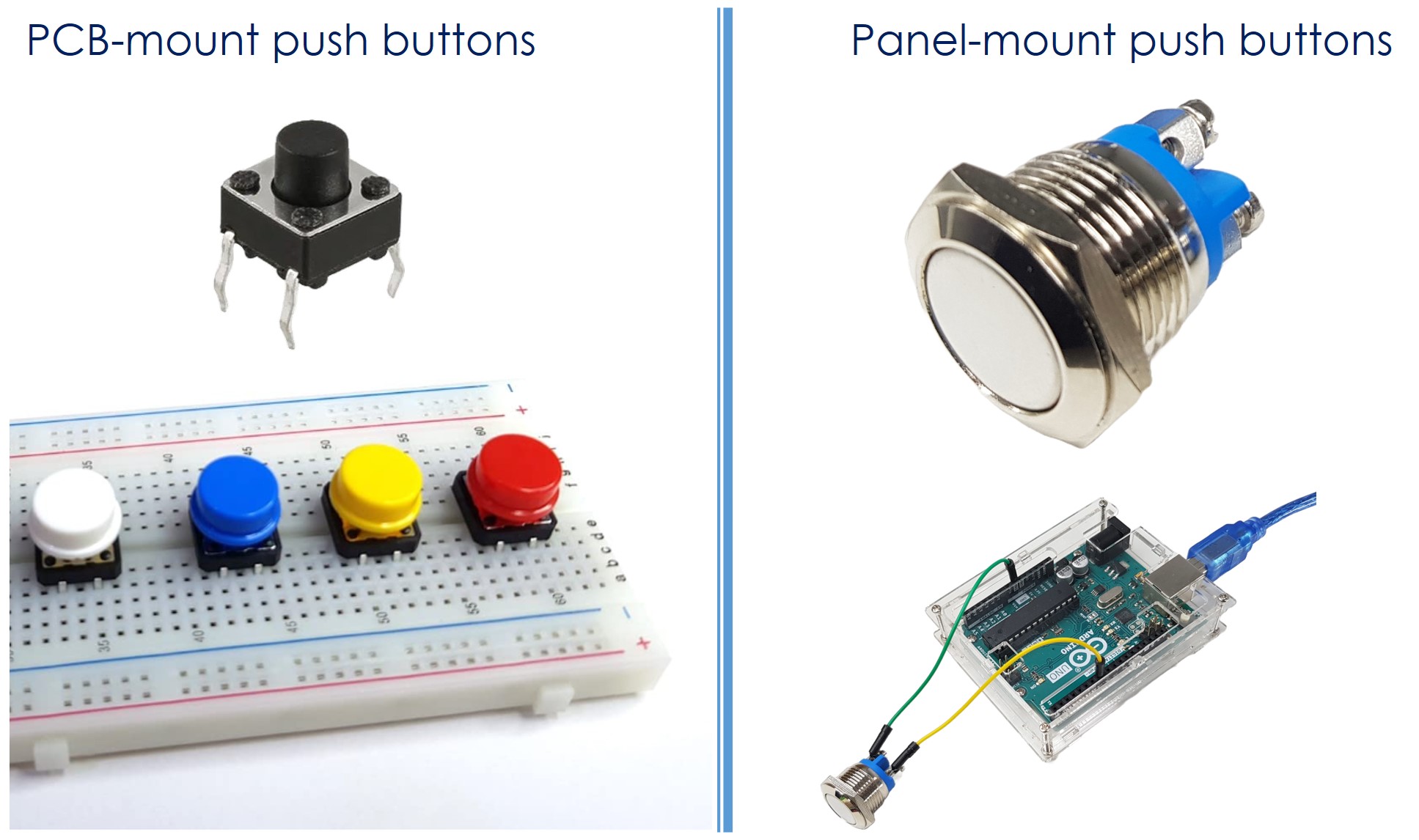
There are various types of push buttons, broadly categorized into three groups based on mounting and functionality:
- PCB-mount push buttons (breadboard-mountable)
- Panel-mount push buttons
Pinout
Understanding the pinout configuration is critical for reliable button integration. Incorrect connections can result in floating inputs, false triggering, or in extreme cases, damage to the Arduino Giga R1 WiFi's GPIO pins. Each button type presents different electrical connection requirements that must be properly addressed.
The PCB-mount buttons usually have four pins.
VCC Pin: Power supply connection, typically 3.3V or 5V depending on button module design. Connect to Arduino Giga R1 WiFi 3.3V output to maintain logic level compatibility.
GND Pin: Ground reference connection. Connect to Arduino Giga R1 WiFi GND pin to establish common electrical reference for reliable switching detection.
Signal Pins (2-4 pins): Contact pins that provide the switching function. Internal connections vary by manufacturer but follow standard patterns for mechanical stability.
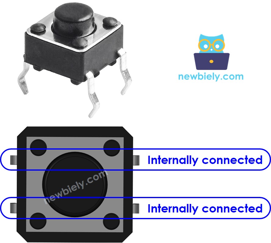
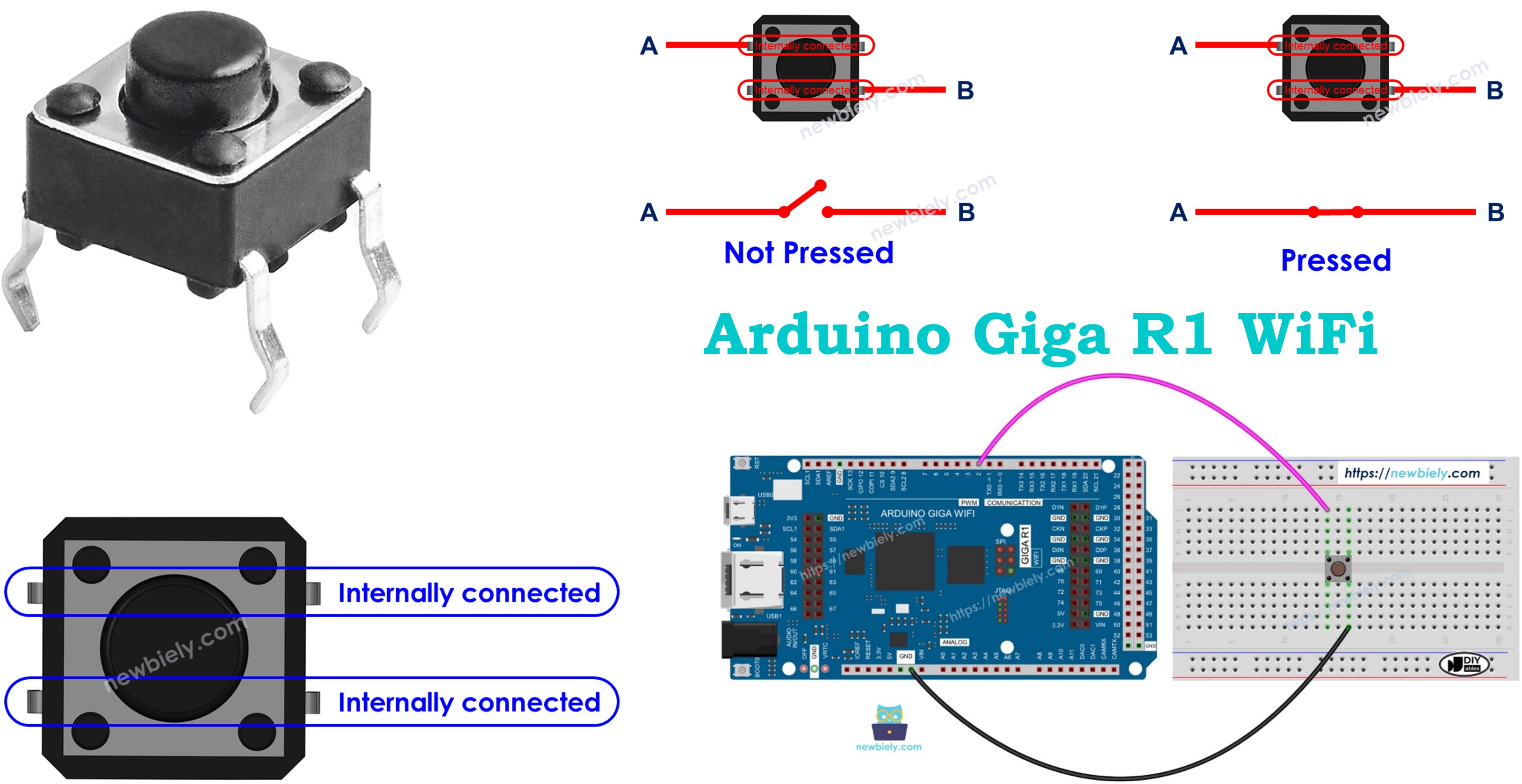
However, these pins are internally connected in pairs. Therefore, we only need to use two of the four pins, which are NOT internally connected. The four-pin configuration provides mechanical stability under repeated pressing forces while maintaining reliable electrical contact. Pin pairs are typically connected diagonally to distribute mechanical stress evenly across the switch body.
There are four ways (actually two ways because of symmetry) to connect to button (see image). The Arduino Giga R1 WiFi's GPIO pins can source or sink up to 25mA, providing adequate current for button interface circuits with appropriate pull-up resistor values.
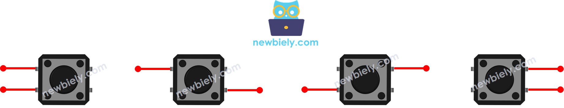
Technical Note: The four-pin design serves a dual purpose - electrical redundancy and mechanical stability. While only two pins are electrically necessary, the additional pins prevent mechanical rotation and provide resistance against the repeated pressing forces that could damage single-point solder connections.
⇒ To make it stand firmly in PCB (board) to resist the pressing force.
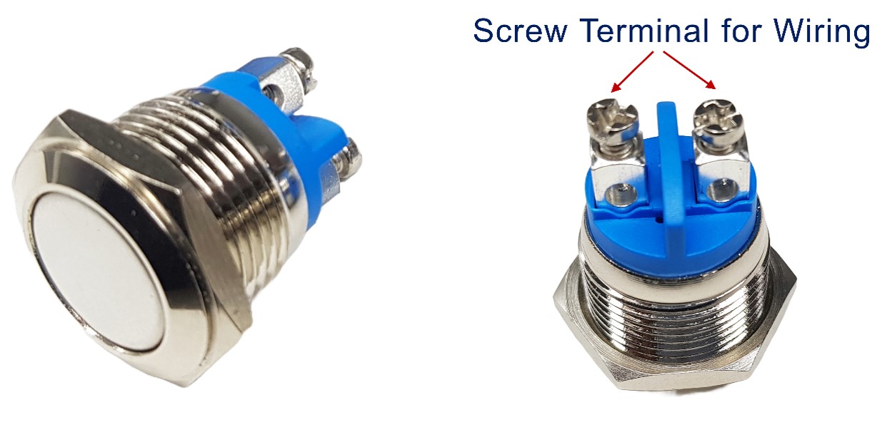
The panel-mount buttons usually have two pins.
Terminal 1: First contact point for circuit connection. Can be connected to either supply voltage or ground depending on pull-up/pull-down configuration.
Terminal 2: Second contact point that connects to Arduino Giga R1 WiFi GPIO pin configured as digital input with internal pull-up enabled.
The push button module includes an built-in pull-down resistor, which ensures that the output remains LOW when the button is not pressed. It has three pins:
GND: Ground connection operating at 0V reference. Connect to Arduino Giga R1 WiFi GND pin to establish electrical reference.
VCC: Power supply input accepting 3.3V to 5V. Connect to Arduino Giga R1 WiFi 3.3V output for optimal compatibility with the board's logic levels.
OUT: Digital output signal that transitions between 0V (LOW) and VCC level (HIGH). Connect to any digital input pin on the Arduino Giga R1 WiFi configured as INPUT mode.
With this configuration, the module outputs LOW when the button is not pressed and outputs HIGH when the button is pressed. The integrated pull-down resistor (typically 10kΩ) eliminates floating input states and ensures reliable logic level detection. This configuration is ideal for beginners as it eliminates external component requirements.
How It Works
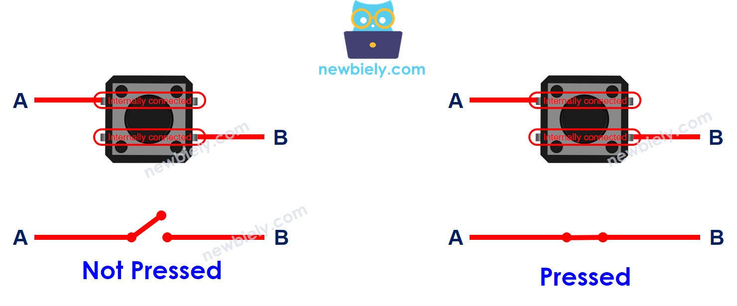
The fundamental operation principle involves mechanical contact closure under applied force. The switching mechanism utilizes a spring-loaded contact system where pressing the button overcomes spring tension to close electrical contacts, completing the circuit path between input terminals.
- When the button is NOT pressed, pin A is NOT connected to pin B - the contacts remain open, creating infinite resistance between terminals
- When the button is pressed, pin A is connected to pin B - the contacts close, creating a low-resistance path (typically <100mΩ) for current flow
The contact closure process occurs within 2-5ms of actuation, but mechanical bounce creates multiple make-break cycles during initial contact. This bounce phenomenon generates rapid voltage transitions that can be interpreted as multiple button presses by fast microcontroller polling routines. Professional implementations address this through hardware debouncing circuits or software algorithms that ignore transitions within the bounce period.
Arduino - Button
Button integration with the Arduino Giga R1 WiFi requires proper electrical interface design to ensure reliable state detection. One button's pin is connected to VCC or GND. The other pin is connected to an Arduino pin configured as a digital input with appropriate pull-up or pull-down biasing.
By reading the state of Arduino's pin (configured as input pin), we can detect the button is pressed or NOT. The Arduino Giga R1 WiFi's advanced GPIO architecture includes programmable pull-up resistors, eliminating external component requirements while providing reliable logic level detection for professional applications.
Button State and Pressing State
The relationship between physical button state and logical pressing state depends on circuit configuration and Arduino pin settings. Understanding this relationship is essential for implementing reliable user interface systems with predictable behavior across different operating conditions.
The relation between the button state and the pressing state depends on how we connect the button with Arduino and the setting of the Arduino's pin.
There are two ways to use a button with Arduino:
- Active-High Configuration: One button's pin is connected to VCC, the other is connected to an Arduino's pin with a pull-down resistor
- If the button is pressed, Arduino's pin state is HIGH. If otherwise, Arduino's pin state is LOW
- We MUST use an external resistor (typically 10kΩ) to prevent floating input states
- Current flows from VCC through the button to the Arduino pin when pressed
- If the button is pressed, Arduino's pin state is LOW. If otherwise, Arduino's pin state is HIGH
- We can use either an internal (40kΩ) or external (10kΩ) resistor. The internal resistor is built inside Arduino Giga R1 WiFi
- Current flows from the internal pull-up through the button to GND when pressed
※ NOTE THAT:
If we do NOT use neither pull-down nor pull-up resistor, the state of the input pin is "floating" when the button is NOT pressed. It means the state can be HIGH or LOW (unstable, unfixed), resulting in the wrong detection.
- The worst practice: initializes the Arduino pin as an input (by using pinMode(BUTTON_PIN, INPUT)) and does NOT use any external pull-down/pull-up resistor.
- The best practice: initializes the Arduino pin as an internal pull-up input (by using pinMode(BUTTON_PIN, INPUT_PULLUP)). It does NOT need to use any external pull-down/pull-up resistor.
To make it easy for beginners, this tutorial uses the simplest method: initializes the Arduino pin as an internal pull-up input without using the external resistor. The beginners do NOT need to care about how to wire the pull-up/pull-down resistor. The beginners just need to use the Arduino code.
Technical Implementation Note: The Arduino Giga R1 WiFi's internal pull-up resistors are implemented within the STM32H747XI microcontroller's GPIO peripheral, providing approximately 40kΩ resistance. This value ensures adequate bias current while minimizing power consumption, making it ideal for battery-powered applications where multiple buttons might be monitored continuously.
Wiring Diagram
The following diagrams demonstrate proper electrical connections between the Arduino Giga R1 WiFi and various button types. Correct wiring ensures reliable operation and prevents damage to the microcontroller's GPIO pins through overcurrent or incorrect voltage application.
Electrical Note: The diagrams below show the minimum viable connection for development and prototyping. For production or extended-use applications, consider adding a 100nF ceramic capacitor across the button terminals to reduce electromagnetic interference and improve noise immunity in electrically noisy environments.
- Wiring Diagram between Arduino and PCB-mount button
| Component Pin | Arduino Giga R1 WiFi Pin |
|---|---|
| Button Terminal 1 | GND |
| Button Terminal 2 | Digital Pin 7 |
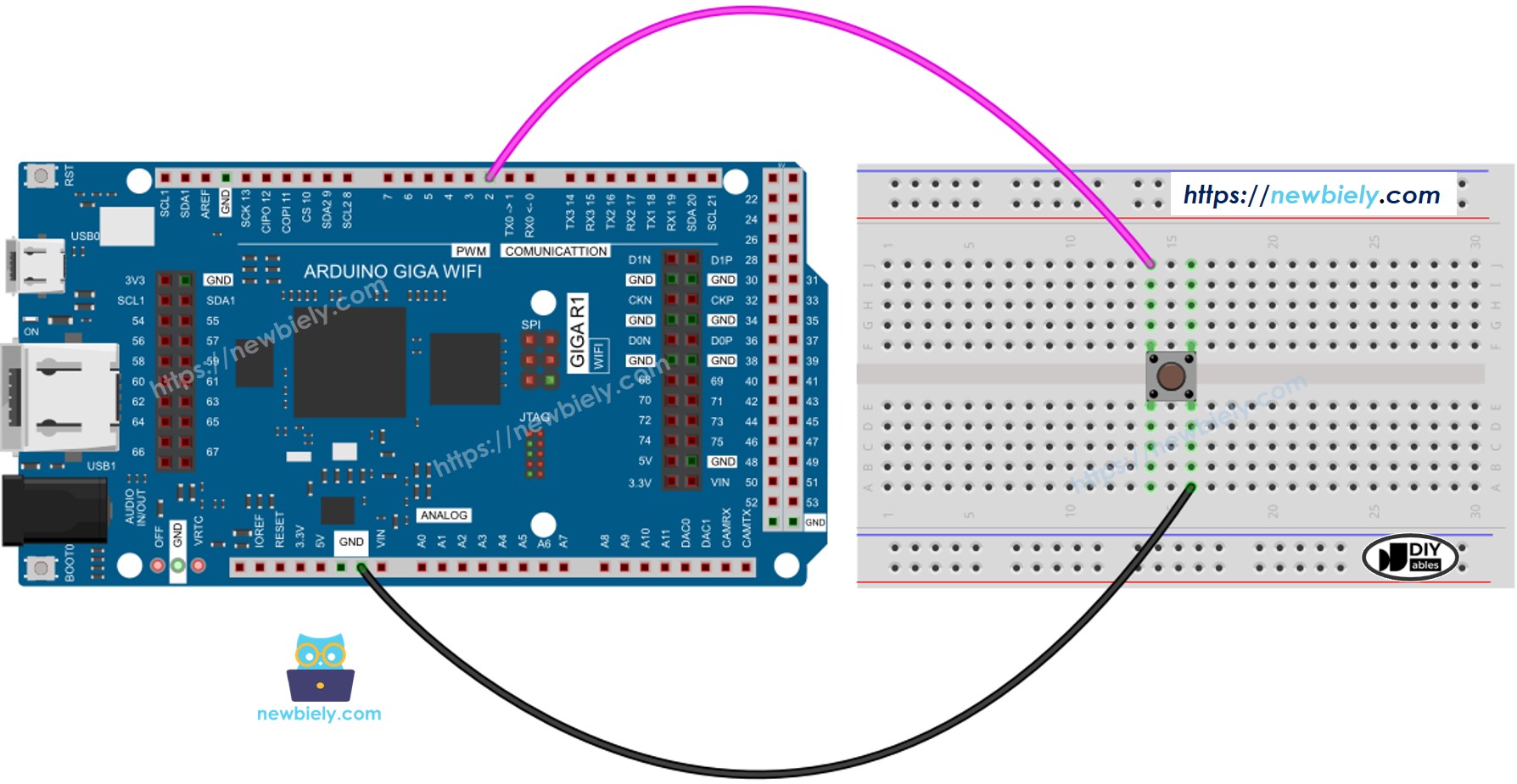
This image is created using Fritzing. Click to enlarge image
- Wiring Diagram between Arduino and panel-mount button
| Component Pin | Arduino Giga R1 WiFi Pin |
|---|---|
| Button Terminal 1 | GND |
| Button Terminal 2 | Digital Pin 7 |
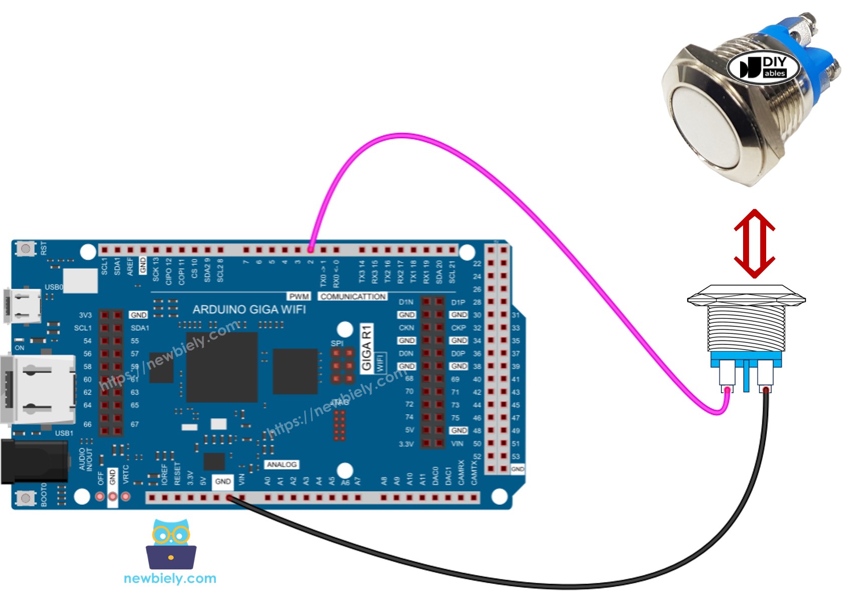
This image is created using Fritzing. Click to enlarge image
Power Supply Requirements: Standard tactile switches require no external power supply as they operate as passive switching elements. The Arduino Giga R1 WiFi's internal pull-up resistor provides the necessary bias current (approximately 82µA at 3.3V) for reliable logic level detection without external components.
Current Consumption: Button interface circuits consume minimal power, with quiescent current limited by the pull-up resistor value. Using the internal 40kΩ pull-up resistor results in standby current of approximately 82µA, making it suitable for low-power applications where multiple buttons are monitored continuously.
Arduino Code
The following implementation demonstrates basic button state monitoring using the Arduino Giga R1 WiFi's digital input capabilities. The code is structured to handle continuous polling with serial output for development and debugging purposes. Key sections include pin initialization, state reading, and output formatting for clear monitoring of button behavior.
Detailed Instructions
For initial Arduino Giga R1 WiFi setup, refer to the Arduino Giga R1 WiFi Getting Started guide before proceeding.
- Connect Hardware: Wire the button to Arduino Giga R1 WiFi pin 7 and GND according to the wiring diagram. Verify connections are secure and correct before applying power.
- Open Arduino IDE: Launch the Arduino IDE and confirm the Arduino Giga R1 WiFi board is selected in the Tools menu. Set the appropriate COM port for your connection.
- Load Code: Copy the button monitoring code below and paste it into a new Arduino IDE sketch. Review the pin assignments and modify if using different GPIO pins.
- Upload Code: Click the Upload button to compile and transfer the code to the Arduino Giga R1 WiFi. Monitor the compilation process for any errors or warnings.
- Open Serial Monitor: Access the Serial Monitor from the Tools menu and set the baud rate to 9600. This displays real-time button state information for monitoring and debugging.
- Test Operation: Press and release the button while observing the Serial Monitor output. Verify that state changes are detected correctly and timing appears responsive.
- Verify Logic Levels: Confirm that unpressed button shows HIGH (1) and pressed button shows LOW (0) when using INPUT_PULLUP configuration. Inconsistent readings indicate wiring errors.
Technical Note: The Arduino Giga R1 WiFi's dual-core architecture allows button monitoring to run independently of other tasks using FreeRTOS task scheduling. For complex applications, consider implementing button handling in a dedicated task to ensure responsive user interface behavior.
- Click Upload button on Arduino IDE to upload code to Arduino
- Open Serial Monitor
- Press and release the button several time
- See the result on Serial Monitor:
1 is HIGH, 0 is LOW.
Code Explanation
Read the line-by-line explanation in comment lines of code!
Modifying Arduino Code
The following modification demonstrates event-driven button handling that detects press and release actions rather than continuous state monitoring. This approach is more suitable for applications requiring specific response to user actions, such as menu navigation, device control, or state toggling functions.
Let's modify the code to detect the press and release events
Detailed Instructions
- Modify Implementation: Replace the continuous state monitoring with edge detection logic that identifies press and release events. This reduces serial output volume and focuses on meaningful user interactions.
- Update Code: Copy the modified button event detection code and replace the previous implementation. The new version tracks state transitions rather than absolute states.
- Upload Modified Code: Compile and upload the updated code to the Arduino Giga R1 WiFi. Monitor for compilation errors that might indicate syntax issues or missing dependencies.
- Test Event Detection: Press and release the button deliberately while monitoring the Serial Monitor. Each press action should generate one press event and one release event message.
- Verify Event Timing: Observe that events are detected immediately upon button action without significant delay. The Arduino Giga R1 WiFi's fast GPIO polling ensures responsive event detection.
- Check for Multiple Events: Note that mechanical button bounce may cause multiple event detections per physical press. This is normal behavior that can be addressed through debouncing techniques.
Technical Note: Event-driven button handling reduces processor overhead by responding only to state changes rather than continuous polling. For applications monitoring multiple buttons, this approach scales better and reduces power consumption in battery-operated systems.
- Click Upload button on Arduino IDE to upload code to Arduino
- Open Serial Monitor
- Press the button and then release
- See the result on Serial Monitor
※ NOTE THAT:
- Even you pressed and released the button only once, the output in Serial Monitor may show several pressed and release events. This is the normal behavior of the button. This behavior is called the "chattering phenomenon". You can learn more in Arduino - Button Debounce tutorial.
- To make it much easier for beginners, especially when using multiple buttons, we created a library, called ezButton. You can learn about ezButton library here.
- Use pinMode(BUTTON_PIN, INPUT) for the button module. It outputs LOW when not pressed and HIGH when pressed.
Challenge Yourself
Implement these advanced button control systems to deepen your understanding of embedded interface design and expand the practical capabilities of your Arduino Giga R1 WiFi projects:
Challenge: Implement LED control with immediate button response — Create a system where an LED turns ON when the button is pressed and OFF when released. Add PWM brightness control based on press duration for advanced functionality.
Challenge: Design a toggle system with state persistence — Build a button interface that toggles an LED between ON and OFF states with each press, maintaining the state across power cycles using the Arduino Giga R1 WiFi's built-in storage capabilities.
Challenge: Create a multi-function button interface — Implement short press, long press, and double-click detection using a single button. Each action should trigger different responses, demonstrating advanced event processing with the Giga R1 WiFi's timing capabilities.
Challenge: Build a button matrix controller — Connect 4 buttons in a 2x2 matrix configuration and implement scanning algorithms to detect individual button presses. Utilize the Arduino Giga R1 WiFi's abundant GPIO pins for efficient matrix scanning.
Challenge: Implement WiFi-connected button control — Use the Arduino Giga R1 WiFi's built-in WiFi capabilities to send button press events to a remote server or mobile app, creating an IoT button interface for smart home applications.
Application Ideas
Button interfaces serve as fundamental components in numerous professional and industrial applications where reliable user interaction is essential:
Industrial Control Panel: Implement emergency stop buttons, process control switches, and mode selection interfaces for manufacturing equipment. The Arduino Giga R1 WiFi's robust GPIO design enables reliable operation in electrically noisy industrial environments with proper shielding and debouncing.
Smart Home Controller: Create centralized control systems for lighting, HVAC, and security functions using multiple buttons with the Arduino Giga R1 WiFi's WiFi connectivity. The board's dual-core architecture enables simultaneous local button processing and wireless communication for responsive smart home integration.
Data Logger Interface: Build portable measurement systems where buttons control logging functions, mode selection, and data upload processes. The Arduino Giga R1 WiFi's expanded memory and processing power support complex logging applications with real-time button-controlled data management.
Medical Device Interface: Develop patient monitoring or therapeutic device controls requiring reliable button response and safety interlocks. The board's deterministic timing capabilities ensure critical button functions operate within required response time specifications.
Automotive Test Equipment: Implement diagnostic tool interfaces for automotive applications where buttons control test sequences and parameter selection. The Arduino Giga R1 WiFi's processing power enables real-time test control with immediate button response for professional automotive diagnostics.
Security System Panel: Create access control and alarm system interfaces using button inputs for code entry, system arming, and emergency functions. Integration with the board's communication capabilities enables remote monitoring and control of security button interfaces.
Challenge Yourself
- Basic Implementation: Turn on LED when button is pressed and turn off LED when button is NOT pressed. Implement immediate response without noticeable delay for professional user experience.
- Toggle Control System: Toggle LED between ON and OFF each time the button is pressed. Add state indication through different LED patterns to confirm toggle operation success.
- Multi-Button Interface: Implement a 4-button keypad system where each button controls different functions. Use the Arduino Giga R1 WiFi's interrupt capabilities for immediate response to any button press.
- Wireless Button Control: Utilize the Arduino Giga R1 WiFi's built-in connectivity to transmit button events to a remote device or web server. Implement reliable transmission with error handling and acknowledgment protocols.
- Advanced Debouncing System: Create a software debouncing algorithm that handles multiple buttons simultaneously while maintaining precise timing. Use the dual-core architecture to dedicate processing resources for reliable button handling.
Additional Knowledge
Understanding when to implement pull-up or pull-down resistors is crucial for reliable embedded system design and prevents common interface problems that can compromise system reliability:
- Requirement for Pull Resistors: If the sensor has either closed (connected to VCC or GND) or open (NOT connected to anything) states, you need a pull-up or pull-down resistor to make these states become two defined logic levels: LOW and HIGH. This applies to mechanical switches, reed switches, push-buttons, magnetic contact switches (door sensor), and any device that provides open-circuit or short-circuit states rather than defined voltage levels.
- No Pull Resistor Required: If the sensor has two defined voltage levels (LOW and HIGH), you do NOT need a pull-up or pull-down resistor because the device actively drives the output to specific voltage levels. For example, motion sensor, touch sensor, and digital sensor modules with integrated signal conditioning circuits provide clean logic levels without external biasing components.
Technical Implementation Guidelines: The Arduino Giga R1 WiFi's internal pull-up resistors (approximately 40kΩ) are suitable for most button applications and eliminate external components. For applications requiring faster switching speeds or lower power consumption, external pull-up resistors in the 1kΩ to 10kΩ range provide improved performance at the cost of increased current consumption.