Arduino Giga R1 WiFi Motion Sensor
This guide covers HC-SR501 motion sensor integration with the Arduino Giga R1 WiFi — from hardware setup to working code. The HC-SR501 is a proven PIR (Passive Infrared) sensor solution for motion detection applications, offering reliable human and animal detection through infrared radiation sensing. Combined with the Arduino Giga R1 WiFi's dual-core processing power and extensive GPIO capabilities, it enables sophisticated automation systems with real-time responsiveness.
When you approach automatic doors, motion-activated lighting, or smart security systems, the technology behind these applications often relies on PIR motion sensors like the HC-SR501. This sensor detects infrared radiation changes caused by moving warm bodies, making it ideal for human presence detection in residential, commercial, and industrial environments. The device operates on simple digital logic — outputting HIGH when motion is detected and LOW during inactive periods.
This tutorial provides complete implementation guidance for Arduino Giga R1 WiFi motion sensor projects. You'll learn the sensor's operating principles, proper wiring techniques, and code structure for both basic motion detection and advanced applications with configurable timing and sensitivity. The Arduino Giga R1 WiFi's generous memory capacity and processing speed make it particularly well-suited for complex motion-based automation that requires multiple sensor inputs, wireless connectivity, or real-time data logging.
The tutorial covers hardware integration, pinout specifications, programming fundamentals, and practical applications. By the end, you'll understand how to implement reliable motion detection systems and integrate them into larger automation projects. We'll also explore the HC-SR501's adjustable parameters — detection range, time delay, and trigger modes — enabling you to optimize sensor behavior for specific use cases.
Hardware Preparation
Or you can buy the following kits:
| 1 | × | DIYables Sensor Kit (18 sensors/displays) |
Additionally, some of these links are for products from our own brand, DIYables .
Overview of HC-SR501 Motion Sensor
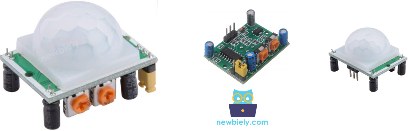
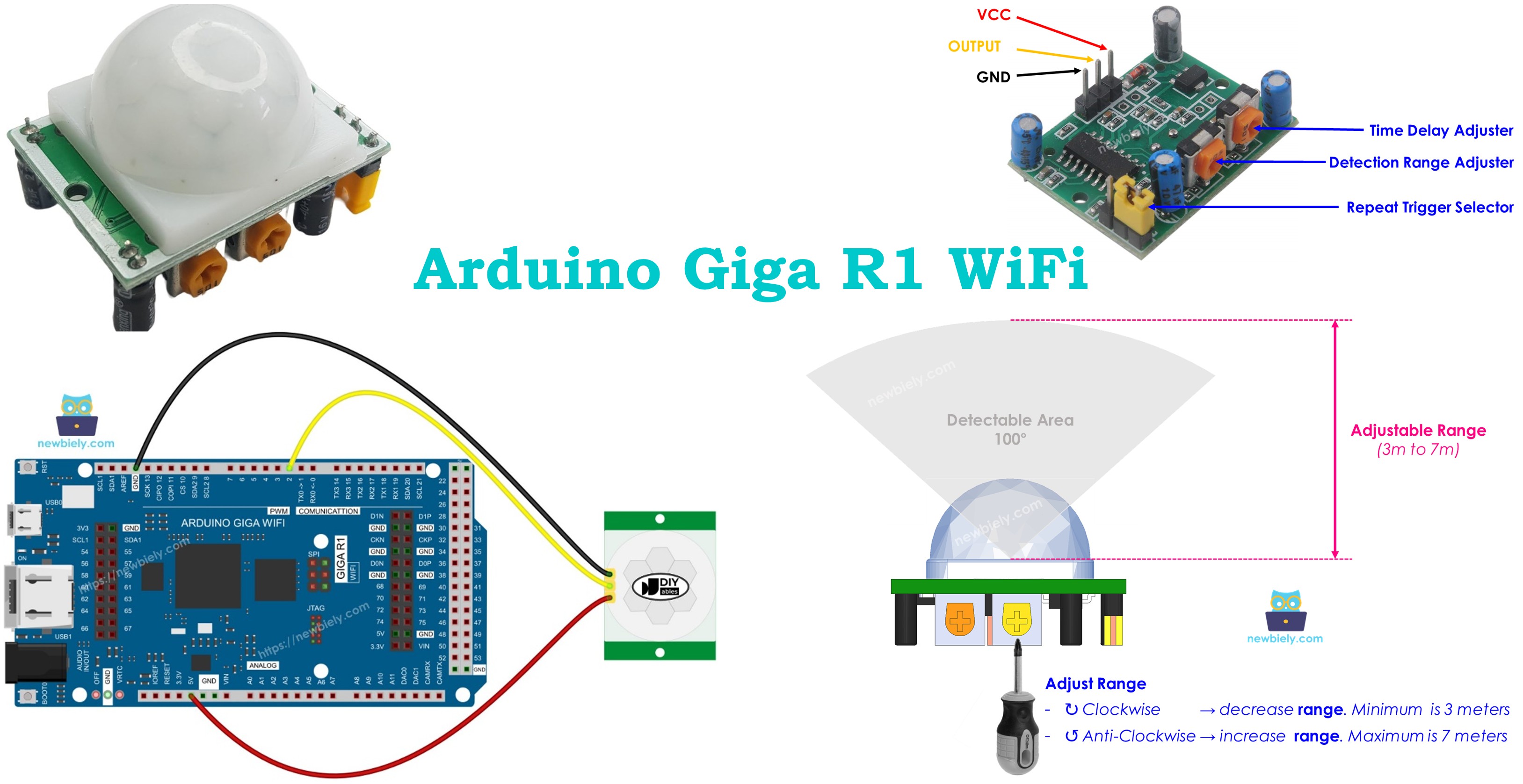
The HC-SR501 is a passive infrared (PIR) motion sensor designed for reliable detection of human and animal movement in automation applications. This sensor operates by detecting changes in infrared radiation within its field of view, making it highly effective for presence detection systems. The device features adjustable sensitivity, detection range from 3-7 meters, and configurable timing parameters that make it suitable for diverse applications from simple motion alarms to complex building automation systems.
The sensor utilizes a pyroelectric detector element that responds to infrared radiation in the 8-12 micrometer wavelength range — the spectrum naturally emitted by warm-blooded creatures. When a heat source moves across the sensor's detection field, it creates a differential signal that triggers the output. The HC-SR501 incorporates signal conditioning circuitry, including amplification and filtering stages, to minimize false triggering from environmental noise while maintaining high sensitivity to legitimate motion events.
Key specifications include a 5V DC operating voltage, less than 65mA current consumption, and TTL-compatible digital output. The sensor requires a 30-60 second initialization period after power-on to stabilize its internal circuitry. Detection angle spans approximately 100-110 degrees horizontal and 70 degrees vertical, providing broad area coverage. Operating temperature range extends from -15°C to +70°C, making it suitable for both indoor and outdoor installations.
Integration with the Arduino Giga R1 WiFi leverages the board's robust GPIO capabilities and real-time processing power. The sensor's digital output connects directly to any GPIO pin configured as digital input, requiring no analog-to-digital conversion or complex signal processing. The Arduino Giga R1 WiFi's dual-core architecture enables simultaneous motion monitoring and wireless communication, essential for IoT-enabled security and automation systems.
Compared to ultrasonic or microwave motion sensors, PIR sensors like the HC-SR501 offer excellent power efficiency and immunity to acoustic interference. However, they require line-of-sight detection and can be affected by extreme temperature variations or air currents from heating/cooling systems. For Arduino Giga R1 WiFi applications, these characteristics make the HC-SR501 ideal for indoor automation, security monitoring, and energy-saving lighting control.
Pinout
The HC-SR501 pinout defines the electrical interface required for proper integration with the Arduino Giga R1 WiFi. Correct wiring ensures reliable operation and prevents damage to both the sensor and the microcontroller. Each pin serves a specific function in the sensor's power supply and signal chain.
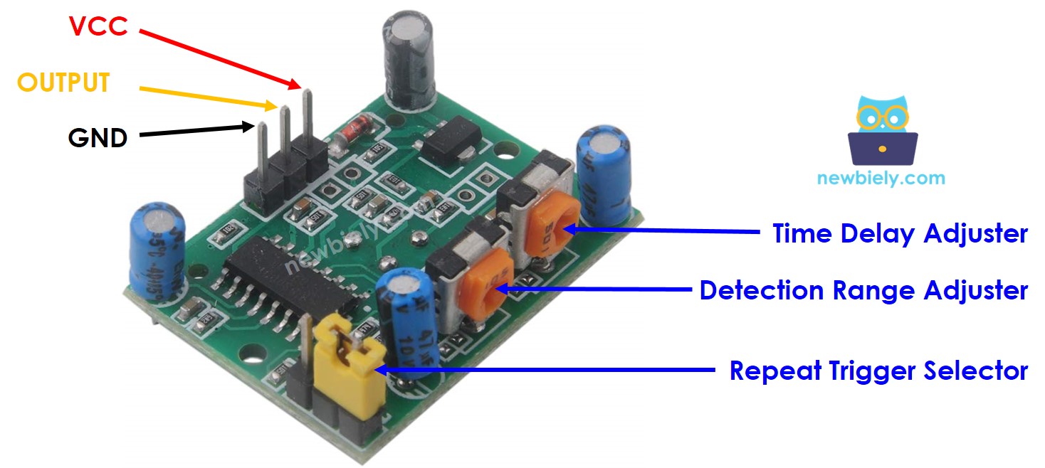
GND: Ground reference (0V). This pin connects to the Arduino Giga R1 WiFi's ground plane and serves as the return path for supply current. Proper grounding is essential for noise immunity and stable operation.
VCC: Power supply input (+5V DC, 65mA maximum). Connects to the Arduino Giga R1 WiFi's 5V output pin. The sensor requires a stable power supply; voltage fluctuations can cause erratic triggering or reduce sensitivity.
OUTPUT: Digital signal output (0V/5V TTL levels). This pin drives HIGH (+5V) when motion is detected and LOW (0V) during inactive periods. The output can source up to 100mA, sufficient for directly driving LEDs or interfacing with Arduino GPIO pins. Connect this pin to any digital input pin on the Arduino Giga R1 WiFi.
The HC-SR501 also features two potentiometers for field adjustment: the sensitivity potentiometer controls detection range (3-7 meters), while the time delay potentiometer sets output duration (3 seconds to 5 minutes). A jumper selects between single-trigger and repeat-trigger modes, affecting the sensor's response to continuous motion.
Electrical Note: The Arduino Giga R1 WiFi's GPIO pins are 5V tolerant, making them fully compatible with the HC-SR501's output levels. No level shifting or current limiting is required for standard connections. For applications requiring longer cable runs, consider adding 100-470 ohm pull-up resistors to improve noise immunity.
How It Works
The HC-SR501 sensor detects motion based on changes in infrared radiation patterns within its detection field. The sensor's pyroelectric element responds to thermal variations caused by warm bodies moving across its field of view. To trigger detection, an object must satisfy two conditions: it must emit infrared radiation in the 8-12 micrometer wavelength range, and it must be moving relative to the sensor's reference frame.
The detection mechanism relies on differential thermal sensing. The pyroelectric detector contains two sensing elements with opposite polarity connections. When the infrared field is uniform, both elements receive equal radiation and their signals cancel. When a warm object moves across the field, it creates an imbalance between the elements, generating a detectable electrical signal. This differential approach provides excellent immunity to gradual temperature changes while maintaining sensitivity to rapid thermal variations.
Humans and animals naturally emit infrared radiation through body heat, making them ideal targets for PIR detection. However, objects at ambient temperature — such as mechanical devices or vehicles — typically don't generate sufficient thermal contrast for reliable detection unless they include heat sources like engines or electrical components.
OUTPUT pin behavior:
- LOW state (0V): No motion detected within the sensor's field of view. This represents the quiescent condition when the thermal field remains stable.
- HIGH state (+5V): Motion detected. The output transitions HIGH when thermal variation exceeds the sensor's threshold, indicating movement of a heat-emitting object.
- Transition timing: The output changes state within 2-3 seconds of motion events, with actual timing dependent on the configured delay settings.
The sensor includes automatic gain control and temperature compensation to maintain consistent sensitivity across its operating temperature range. Environmental factors such as direct sunlight, heating vents, or rapidly changing ambient temperatures can affect performance, requiring careful placement and calibration for optimal results.
Detect the Presence of Human
The HC-SR501 sensor fundamentally detects motion, not static presence. Arduino applications must implement logic to infer human presence based on motion events, understanding that this approach has inherent limitations in scenarios where people remain stationary for extended periods.
The typical presence detection algorithm follows this logic:
- Motion detected → Humans are present: When the sensor output transitions HIGH, the system assumes human presence and activates appropriate responses (lighting, HVAC, security recording).
- No motion detected → Humans may not be present: When the sensor output remains LOW for a configured timeout period, the system assumes the area is unoccupied and deactivates systems to conserve energy.
This approach works effectively in most practical applications but can produce false negatives when people remain motionless for extended periods. For example, in conference rooms or study areas, occupants might sit still during meetings or concentrated work, causing the system to incorrectly conclude the space is vacant. To mitigate this issue, many installations use multiple sensors with overlapping coverage areas or combine PIR sensors with other detection methods like ultrasonic sensors or manual override switches.
The Arduino Giga R1 WiFi's processing capabilities enable sophisticated presence detection algorithms that consider motion patterns, timing intervals, and integration with other sensors. Applications can implement features like grace periods before deactivation, motion pattern analysis to distinguish between human and non-human movement, or wireless connectivity to coordinate between multiple sensors in larger spaces.
For reliable human presence detection in Arduino applications, consider implementing configurable timeout periods, multiple detection zones, and manual override capabilities to handle edge cases where motion-based detection proves insufficient.
Arduino - HC-SR501 Motion Sensor
Arduino GPIO pins configured as digital inputs can read the HC-SR501's output state directly, enabling straightforward motion detection implementation. The Arduino Giga R1 WiFi's 5V-tolerant inputs interface seamlessly with the sensor's TTL output levels, requiring no additional level conversion or signal conditioning.
By connecting the HC-SR501's OUTPUT pin to an Arduino digital input pin, your code can monitor motion events using the digitalRead() function. The sensor's binary output (HIGH for motion detected, LOW for no motion) integrates naturally with Arduino's digital I/O architecture, allowing for simple conditional logic and interrupt-driven processing.
The Arduino Giga R1 WiFi's dual-core architecture provides advantages for motion sensor applications requiring real-time responsiveness combined with wireless communication or data logging. One core can handle immediate motion detection and response, while the other manages network operations, sensor fusion, or user interface tasks.
Wiring Diagram
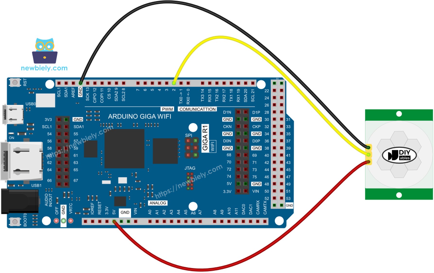
This image is created using Fritzing. Click to enlarge image
The wiring diagram above shows the essential connections between the HC-SR501 motion sensor and Arduino Giga R1 WiFi. This minimal configuration provides reliable motion detection with proper power supply and signal routing. The straightforward three-wire connection makes it suitable for rapid prototyping and permanent installations alike.
Electrical Note: The diagram shows the minimum viable connection for basic operation. For production applications or installations with longer cable runs, consider adding a 100μF electrolytic capacitor between VCC and GND near the sensor to suppress power supply noise, and a 10kΩ pull-up resistor on the OUTPUT line to improve signal integrity in electrically noisy environments.
Power supply considerations: The HC-SR501 draws approximately 65mA during operation, well within the Arduino Giga R1 WiFi's 5V supply capacity. However, ensure your overall power budget accounts for the sensor's consumption, especially in battery-powered applications where power efficiency is critical.
| Component Pin | Arduino Giga R1 WiFi Pin | Function |
|---|---|---|
| GND | GND | Ground reference (0V) |
| VCC | 5V | Power supply (+5V DC) |
| OUTPUT | Pin 2 | Digital motion signal |
Initial Setting
Before implementing motion detection code, configure the HC-SR501's hardware settings for optimal performance. The sensor includes two potentiometers and one jumper that control detection behavior, timing characteristics, and trigger modes. Proper initial configuration ensures predictable operation during development and testing phases.
| Parameter | Initial Setting | Rationale |
|---|---|---|
| Time Delay Adjuster | Screw fully counter-clockwise | Minimum delay (3 seconds) for rapid testing |
| Detection Range Adjuster | Screw fully clockwise | Maximum sensitivity (7 meters) for broad coverage |
| Repeat Trigger Selector | Position jumper as shown | Repeat trigger mode for continuous motion handling |
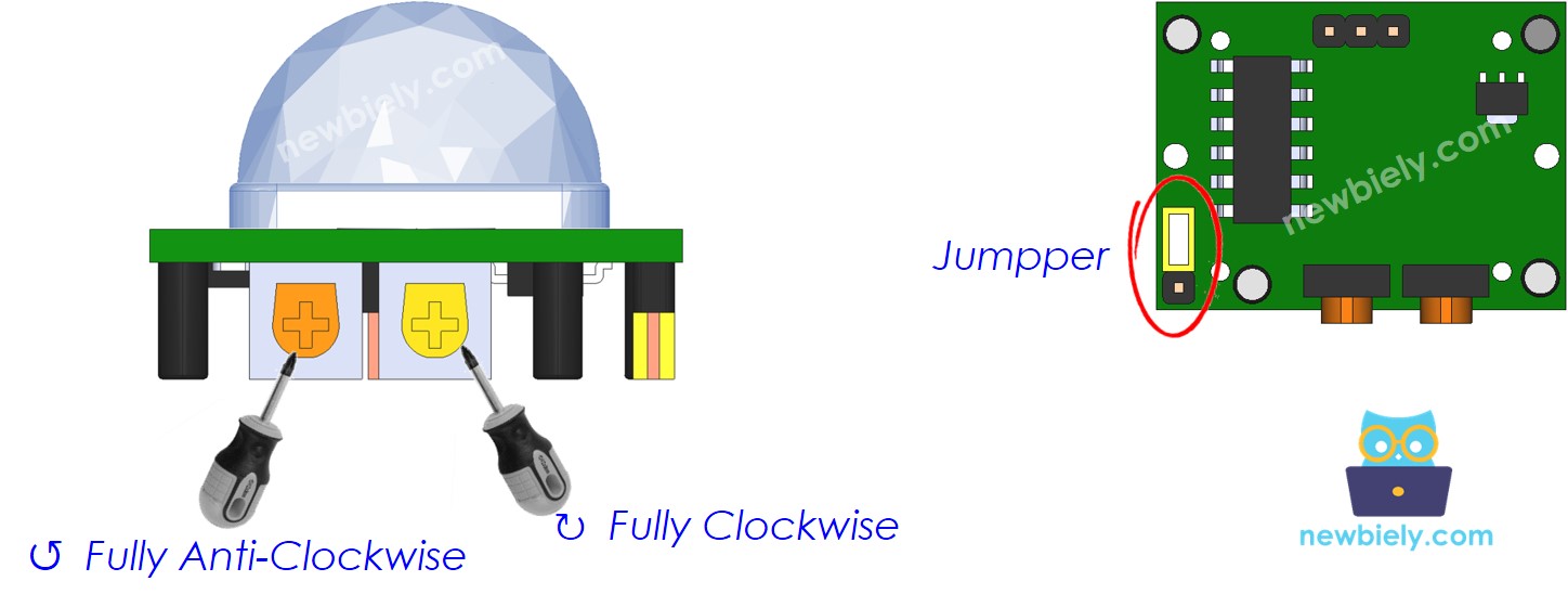
These settings provide maximum detection range with minimum delay time, ideal for development and testing. The repeat trigger mode ensures the output remains HIGH during continuous motion, simplifying Arduino code logic and providing more predictable behavior for automation applications.
Configuration Note: After adjusting potentiometers, allow 30-60 seconds for the sensor to stabilize before testing. The HC-SR501 requires this initialization period to establish its thermal baseline and calibrate internal amplification circuits.
How To Program For Motion Sensor
Programming the Arduino Giga R1 WiFi for motion sensor integration involves configuring GPIO pins, reading digital states, and detecting state transitions. The implementation follows standard digital input procedures with specific attention to edge detection for motion start and stop events.
Initialize Digital Input Configuration:
Configure the Arduino pin connected to the sensor's OUTPUT pin as a digital input. This enables the microcontroller to read the sensor's state changes.
Read Sensor State:
Use digitalRead() to poll the current sensor output state. This function returns HIGH when motion is detected and LOW during inactive periods.
Detect Motion Start Events:
Identify the transition from no motion (LOW) to motion detected (HIGH) by comparing current and previous pin states. This edge detection triggers immediate response to motion events.
Detect Motion Stop Events:
Similarly, detect the transition from motion detected (HIGH) to no motion (LOW) to trigger cleanup actions or deactivation sequences.
This edge-detection approach provides precise control over system responses to motion events, enabling implementation of sophisticated automation logic with the Arduino Giga R1 WiFi's processing capabilities.
Arduino Code
The following implementation demonstrates edge-triggered motion detection with the HC-SR501 sensor. The code structure emphasizes state transition detection rather than simple polling, providing immediate response to motion start and stop events. Key sections handle pin initialization, state management, and event-driven response logic.
Detailed Instructions
Prerequisites: Arduino IDE installed and the Arduino Giga R1 WiFi board package configured. Refer to the Getting Started guide for setup instructions if needed.
- Connect Hardware: Wire the HC-SR501 sensor to the Arduino Giga R1 WiFi according to the wiring diagram. Verify VCC connects to 5V, GND to ground, and OUTPUT to digital pin 2. Double-check connections to prevent damage during power-up.
- Configure Sensor: Adjust the HC-SR501's potentiometers and jumper to initial settings as described above. Set time delay to minimum (counter-clockwise), detection range to maximum (clockwise), and jumper to repeat trigger mode.
- Load Code: Copy the provided Arduino code and open it in the Arduino IDE. Verify the PIN_TO_SENSOR constant matches your wiring configuration (default is pin 2).
- Upload Program: Connect the Arduino Giga R1 WiFi via USB and upload the code. The IDE should report successful compilation and upload. Allow 30-60 seconds after upload for the sensor to initialize and stabilize.
- Open Serial Monitor: Launch the Serial Monitor at 9600 baud to observe motion detection events. The monitor will display real-time motion start and stop messages.
- Test Motion Detection: Move your hand or walk in front of the sensor within its detection range (up to 7 meters). The serial monitor should display "Motion detected!" when movement begins and "Motion stopped!" when you remain still or move out of range.
- Verify Timing: Observe the sensor's response to different motion patterns. Continuous movement should maintain HIGH output in repeat trigger mode, while stopping motion should trigger LOW output after the configured delay period.
- Debug Connection Issues: If no output appears, verify wiring connections, power supply voltage (should be 5V), and sensor initialization time. Check that the Arduino Giga R1 WiFi is properly communicating via Serial Monitor.
Technical Note: The HC-SR501 requires line-of-sight detection and responds best to lateral movement across its field of view rather than direct approach/retreat motion. For optimal sensitivity, position the sensor to detect cross-field movement patterns in your application environment.
Serial Monitor Output
Application Ideas
Automatic Lighting Control: Implement energy-efficient lighting systems that activate when occupants enter rooms and deactivate after configurable timeout periods. The Arduino Giga R1 WiFi's processing power enables sophisticated scheduling algorithms that consider time-of-day, ambient light levels, and occupancy patterns for optimal energy management.
Security Monitoring System: Create perimeter monitoring applications that detect unauthorized movement and trigger alarm responses. Integration with the Arduino Giga R1 WiFi's WiFi capabilities enables real-time alert transmission to smartphones or central monitoring systems, with data logging for pattern analysis and forensic review.
HVAC Automation Controller: Develop occupancy-based climate control that adjusts heating, cooling, and ventilation based on room occupancy. The dual-core architecture allows simultaneous motion monitoring and temperature control, optimizing comfort while reducing energy consumption in commercial and residential buildings.
Industrial Equipment Safety System: Implement safety interlocks for manufacturing equipment that automatically shut down machinery when personnel enter restricted areas. The Arduino Giga R1 WiFi's real-time response capabilities ensure rapid safety system activation with configurable grace periods for authorized maintenance access.
Smart Home Integration Hub: Build comprehensive home automation systems that coordinate multiple motion sensors throughout a residence. The Arduino Giga R1 WiFi's WiFi connectivity enables integration with popular home automation platforms, allowing motion-triggered scenes, security monitoring, and energy management from central interfaces.
Data Logging and Analytics Platform: Create occupancy monitoring systems for space utilization analysis in offices, retail environments, or public facilities. The Arduino's expanded memory capacity supports local data storage with periodic transmission to cloud services for trend analysis and facility optimization.
Video Section
The accompanying video demonstrates the hardware assembly process and live code execution with the HC-SR501 motion sensor. It covers proper wiring techniques, sensor configuration procedures, and real-time motion detection behavior. The demonstration shows expected serial monitor output patterns and illustrates the sensor's response to various motion types within its detection field.
Challenge Yourself
Challenge: Implement a multi-zone motion detection system using three HC-SR501 sensors to monitor different areas simultaneously. Use the Arduino Giga R1 WiFi's multiple GPIO pins to track occupancy patterns and determine room-to-room movement flow for building analytics applications.
Challenge: Create a motion-activated security camera trigger system that interfaces with a USB camera module via the Arduino Giga R1 WiFi's USB host capability. Implement intelligent recording that starts video capture on motion detection and uploads files to a network storage location using WiFi connectivity.
Challenge: Build a power-efficient battery-operated motion detector that uses the Arduino Giga R1 WiFi's sleep modes to extend operation time. Implement wake-on-motion functionality using interrupt-driven detection, with periodic WiFi status reporting and configurable sensitivity adjustment via a web interface.
Challenge: Develop a machine learning-enhanced motion classifier that distinguishes between human, pet, and mechanical movement patterns. Use the Arduino Giga R1 WiFi's processing power to implement basic pattern recognition algorithms that reduce false triggers in complex environments with multiple heat sources.
Challenge: Create a comprehensive building automation system that integrates motion detection with environmental sensors (temperature, humidity, light level) to implement intelligent space management. Use the dual-core architecture to handle real-time sensor monitoring while maintaining continuous WiFi connectivity for remote monitoring and control.
Advanced Uses
The HC-SR501 offers extensive customization through hardware adjustments that modify detection characteristics, timing behavior, and trigger responses. Understanding these parameters enables optimization for specific application requirements and environmental conditions.
Detection Range Adjuster
This potentiometer controls the sensor's detection sensitivity, effectively adjusting the maximum detection distance from approximately 3 to 7 meters. The adjustment modifies the amplification gain of the sensor's internal signal processing circuitry.
- Maximum Range Setting (Counter-clockwise): Detection distance approximately 7 meters. Higher sensitivity increases detection range but may cause false triggering from distant heat sources or air currents.
- Minimum Range Setting (Clockwise): Detection distance approximately 3 meters. Reduced sensitivity provides more reliable operation in environments with thermal noise but limits coverage area.
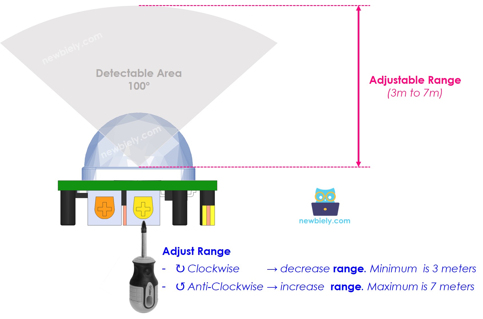
Optimal range adjustment depends on installation environment and application requirements. Indoor applications typically benefit from reduced sensitivity to prevent false triggering from HVAC systems, while outdoor or large-space installations require maximum sensitivity for adequate coverage. The Arduino Giga R1 WiFi can implement software-based range validation by timing detection events and filtering responses that fall outside expected parameters.
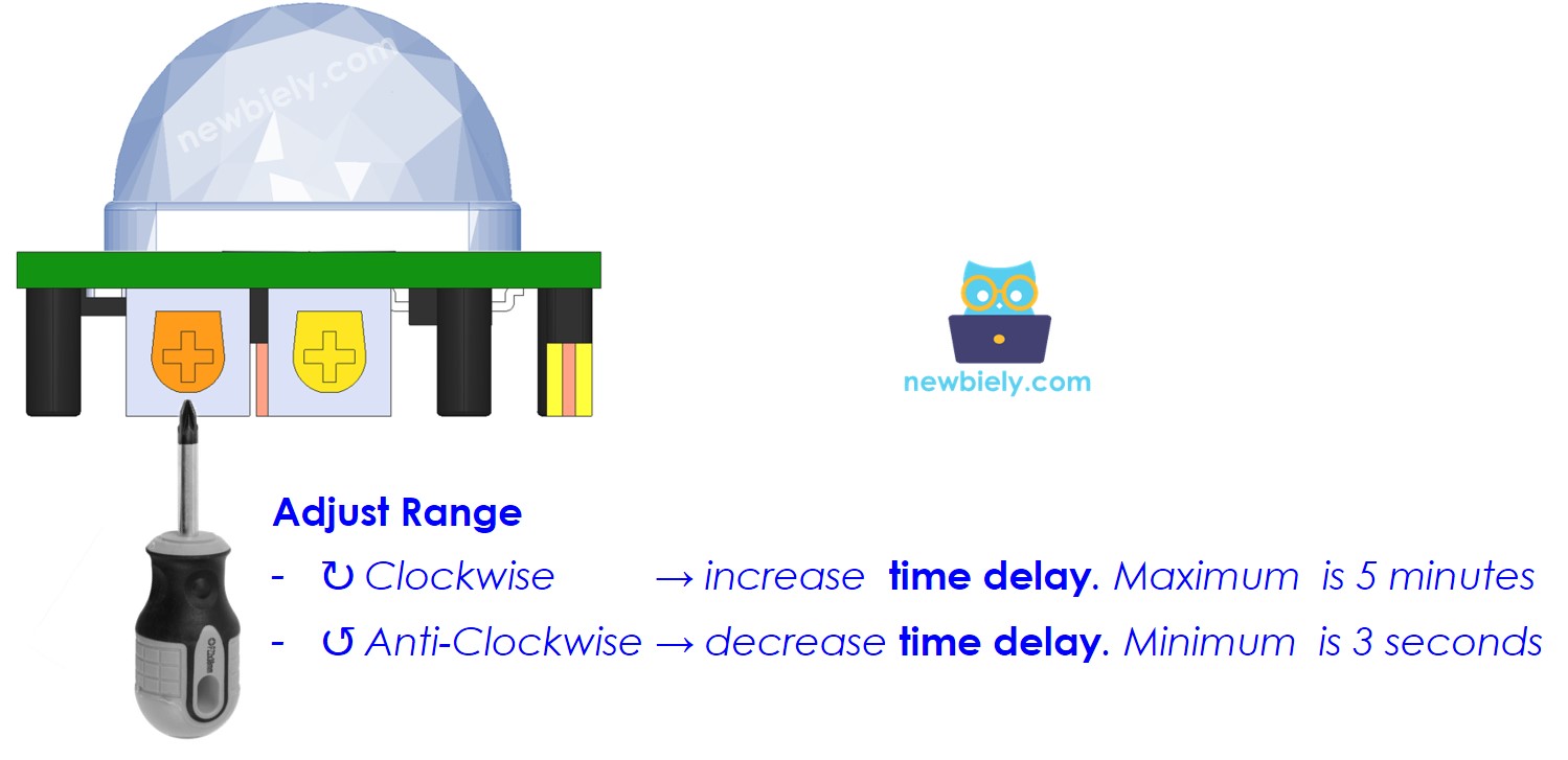
Time Delay Adjuster
This potentiometer sets the duration that the OUTPUT pin remains HIGH after motion detection ends. The adjustment range spans from approximately 3 seconds to 5 minutes, controlling how long activated devices remain on after the last motion event.
- Minimum Delay (Counter-clockwise): Approximately 3 seconds output duration. Suitable for applications requiring rapid response to occupancy changes, such as security systems or high-traffic area lighting.
- Maximum Delay (Clockwise): Approximately 5 minutes output duration. Appropriate for applications where extended activation is desirable, such as bathroom lighting or conference room automation.
The time delay setting interacts with the trigger mode selection to determine overall sensor behavior. Arduino applications can implement additional software-based delays for more precise timing control, using the hardware delay as a minimum activation period and extending it through code logic as needed.
Repeat Trigger Selector
The jumper configuration determines how the sensor responds to continuous motion within its detection field. This setting significantly affects the OUTPUT pin's behavior during extended occupancy periods.
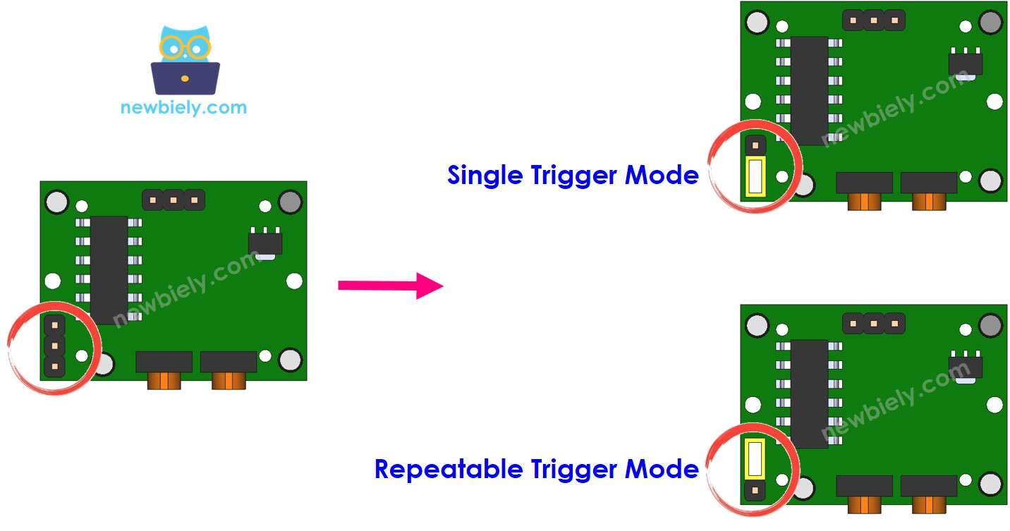
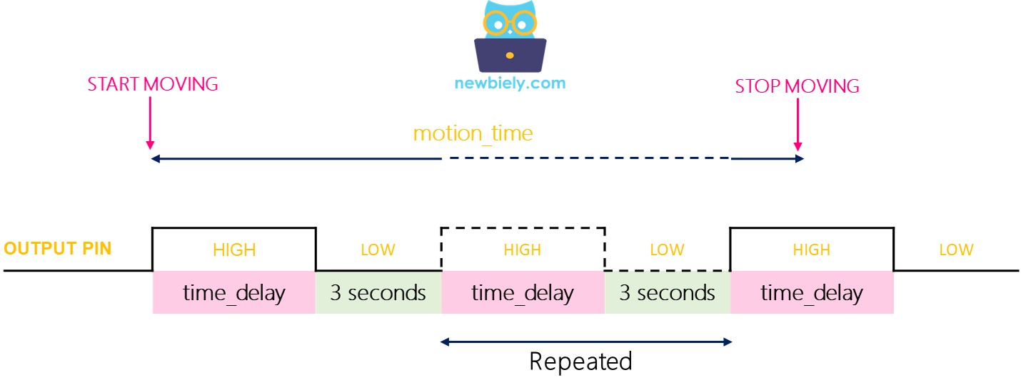
Single Trigger Mode: The OUTPUT pin cycles between HIGH and LOW states during continuous motion, with HIGH duration equal to the configured time delay and LOW duration fixed at 3 seconds. This mode provides periodic confirmation of continued occupancy but creates gaps in the output signal that may cause flickering in connected devices.
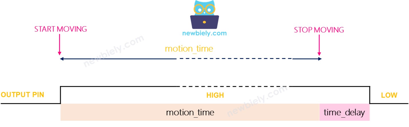
Repeatable Trigger Mode (Recommended): The OUTPUT pin remains HIGH for the entire duration of motion plus the configured time delay. This mode provides stable output during continuous occupancy, making it ideal for lighting and automation applications where consistent activation is required.
Testing Trigger Modes
To observe trigger mode behavior, configure the Time Delay Adjuster to minimum (3 seconds) and test both modes with continuous motion:
Single Trigger Mode Testing:
- Set jumper to single trigger position
- Move continuously in sensor range for 10 seconds
- Stop motion and observe serial output for 6-9 seconds total
- Expected output shows multiple detection cycles:
Repeatable Trigger Mode Testing:
- Set jumper to repeatable trigger position
- Move continuously in sensor range for 10 seconds
- Stop motion and observe serial output for 13+ seconds total
- Expected output shows single continuous detection period:
The repeatable trigger mode provides more predictable behavior for Arduino applications, eliminating the need to handle rapid state changes during continuous occupancy periods.
※ NOTE THAT:
Both trigger modes include a 3-second blocking period after each LOW transition during which the sensor cannot detect new motion. This hardware limitation prevents immediate re-triggering but rarely affects practical applications. The Arduino Giga R1 WiFi's processing capabilities enable software-based motion pattern analysis to compensate for this limitation in applications requiring continuous monitoring.
How To Use Time Delay
Time delay implementation can occur at the hardware level (sensor configuration) or software level (Arduino code), or both. Understanding the interaction between these delay mechanisms enables precise control over automation timing behavior.
Hardware Delay Only: When relying solely on the sensor's time delay setting, the OUTPUT pin remains HIGH for the configured duration after motion stops. This approach provides simple, reliable timing but limits flexibility for complex applications.
Software Delay Only: Setting the sensor's time delay to minimum (3 seconds) and implementing timing logic in Arduino code provides maximum flexibility. The Arduino Giga R1 WiFi can implement sophisticated algorithms considering multiple inputs, user preferences, and environmental conditions.
Combined Delay: Using both hardware and software delays creates a compound timing effect where the total delay equals the sum of both settings. This approach can provide fail-safe operation where the sensor maintains minimum activation time even if software fails.
Setting Time Delay in Arduino Code
The following implementation demonstrates software-based time delay management, providing precise control over activation timing with configurable parameters and multiple sensor support:
This implementation provides 30 seconds of software delay in addition to the sensor's hardware delay setting. In repeatable trigger mode with minimum hardware delay (3 seconds), the total deactivation delay becomes 33 seconds after motion stops. The Arduino Giga R1 WiFi's millis() function provides precise timing resolution suitable for applications requiring exact timing control.
Challenge Yourself
Challenge: Implement an intelligent lighting controller that adjusts activation timeout based on time of day and ambient light levels. Use the Arduino Giga R1 WiFi's real-time clock capabilities and analog inputs to create context-aware automation that extends timeout periods during evening hours and reduces them during peak daylight.
Challenge: Create a multi-sensor fusion system combining HC-SR501 motion detection with ultrasonic distance measurement to distinguish between human occupancy and small animal movement. Implement logic that requires both motion and appropriate distance readings to trigger activation, reducing false alarms in outdoor installations.
Challenge: Build a wireless sensor network using multiple Arduino Giga R1 WiFi units with HC-SR501 sensors that communicate occupancy data via WiFi mesh networking. Implement distributed decision-making where sensor nodes coordinate to provide building-wide occupancy mapping and energy optimization.
Challenge: Develop a machine learning application that analyzes motion patterns to predict occupancy schedules and optimize HVAC pre-conditioning. Use the Arduino Giga R1 WiFi's processing power to implement basic pattern recognition algorithms that learn from historical motion data and adjust building systems proactively.
Challenge: Create a comprehensive security system that combines motion detection with camera triggering, audio alerts, and smartphone notifications. Implement staged response protocols where different motion patterns trigger appropriate security responses, from silent monitoring to active alarm states.