Arduino Giga R1 WiFi Traffic Light
This guide covers traffic light control with the Arduino Giga R1 WiFi — from hardware setup to advanced programming techniques using millis() timing. The Arduino Giga R1 WiFi's dual-core STM32H747XI processor and generous GPIO resources make it an excellent choice for traffic management systems, prototype intersection controllers, and educational traffic simulation projects.
Traffic light modules are fundamental components in automation and control systems, providing clear visual status indication across industrial, educational, and prototype applications. The three-color LED system (red, yellow, green) offers an intuitive interface that translates directly to real-world traffic control logic. When paired with the Arduino Giga R1 WiFi, these modules enable sophisticated timing sequences, wireless connectivity for networked traffic systems, and the processing power needed for complex intersection management algorithms.
This tutorial walks through complete implementation details, covering basic digital output control, optimized programming patterns, and non-blocking timing techniques. You'll implement standard traffic light sequences using both delay-based and millis()-based approaches, understanding the trade-offs between simplicity and system responsiveness. The Arduino Giga R1 WiFi's 480MHz processing capability ensures precise timing control even when managing multiple traffic signals simultaneously.
The documentation covers hardware integration, pinout specifications, wiring requirements, and three progressively sophisticated code implementations. By the end, you'll have working traffic light control with professional-grade non-blocking timing suitable for real automation projects.
Hardware Preparation
Or you can buy the following kits:
| 1 | × | DIYables Sensor Kit (18 sensors/displays) |
Additionally, some of these links are for products from our own brand, DIYables .
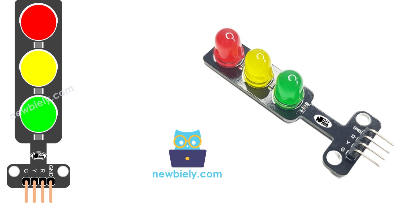
Overview of Traffic Light Module
Traffic light modules are solid-state LED-based indicator devices designed for visual status communication in automation and control systems. These modules integrate three discrete LED elements (red, yellow, green) with current-limiting resistors and a common cathode or anode configuration, typically operating at 5V logic levels with current consumption ranging from 10-20mA per active LED.
The underlying operating principle relies on individual GPIO control of each LED color through dedicated input pins. Each pin accepts standard TTL/CMOS logic levels (0V for LOW, 3.3V-5V for HIGH) to activate the corresponding LED element. The module's internal circuitry includes appropriate current-limiting resistors sized for 5V operation, eliminating the need for external current limiting when interfaced with Arduino digital outputs.
Traffic light modules offer significant advantages over discrete LED implementations: standardized pinout, integrated current limiting, consistent color output, and mechanical housing suitable for panel mounting. Compared to addressable RGB LEDs, traffic light modules provide independent control of each color with simpler wiring requirements and no protocol timing constraints. The Arduino Giga R1 WiFi's abundant GPIO pins (76 digital I/O) easily accommodate multiple traffic light modules for complex intersection simulation.
Integration considerations include power supply capacity (plan for 60mA maximum per module with all LEDs active), GPIO current sourcing limits (20mA per pin maximum on the STM32H747XI), and timing precision requirements for realistic traffic sequences. The module's discrete LED approach provides excellent visibility and color differentiation essential for traffic indication applications.
Pinout
The pinout maps each physical connection to its electrical function in the traffic light control circuit. Correct wiring is essential — an incorrect connection may damage the module or produce unreliable LED operation, particularly if power supply polarity is reversed.
A traffic light module includes 4 pins with the following electrical specifications:
- GND pin: Ground reference, 0V. Connects to Arduino GND to complete the current return path for all LED circuits. This connection must be established first to prevent floating voltages during assembly.
- R pin: Red LED control input, accepts 0-5V logic levels. Connects to any Arduino digital output pin to control red LED state. Internal current limiting sized for 15mA typical draw at 5V supply.
- Y pin: Yellow LED control input, accepts 0-5V logic levels. Connects to any Arduino digital output pin to control yellow LED state. Internal current limiting matched to red LED specifications for consistent brightness.
- G pin: Green LED control input, accepts 0-5V logic levels. Connects to any Arduino digital output pin to control green LED state. Internal current limiting provides uniform LED intensity across all three colors.
The Arduino Giga R1 WiFi's GPIO pins source up to 20mA maximum current, well within the module's 15mA requirement per LED. All three LEDs can be activated simultaneously without exceeding GPIO current limits. Signal logic levels are compatible with both 3.3V and 5V logic systems due to the module's wide input voltage range.
How It Works
The traffic light module operates through individual LED control via digital GPIO signals from the Arduino Giga R1 WiFi. Each color LED (red, yellow, green) responds independently to HIGH/LOW logic states applied to its respective input pin. When a digital output pin is set HIGH (3.3V or 5V), current flows through the corresponding LED and its series current-limiting resistor, illuminating that color. Setting the pin LOW (0V) stops current flow, turning off the LED.
The module's internal architecture uses a common ground configuration where all LED cathodes connect to the GND pin, while individual anodes connect to the R, Y, and G control inputs. This arrangement allows simultaneous control of multiple LEDs by driving their respective input pins HIGH independently. Current limiting resistors, typically 220-330 ohms, are integrated within the module to provide appropriate LED current at 5V supply voltage.
Traffic sequence timing depends entirely on the Arduino program logic. Standard traffic patterns involve sequential activation: red (stop), red+yellow (prepare), green (go), yellow (caution), then repeat. Professional traffic systems implement precise timing intervals — typically 30-60 seconds for green, 3-5 seconds for yellow, with red duration calculated to accommodate cross-traffic timing.
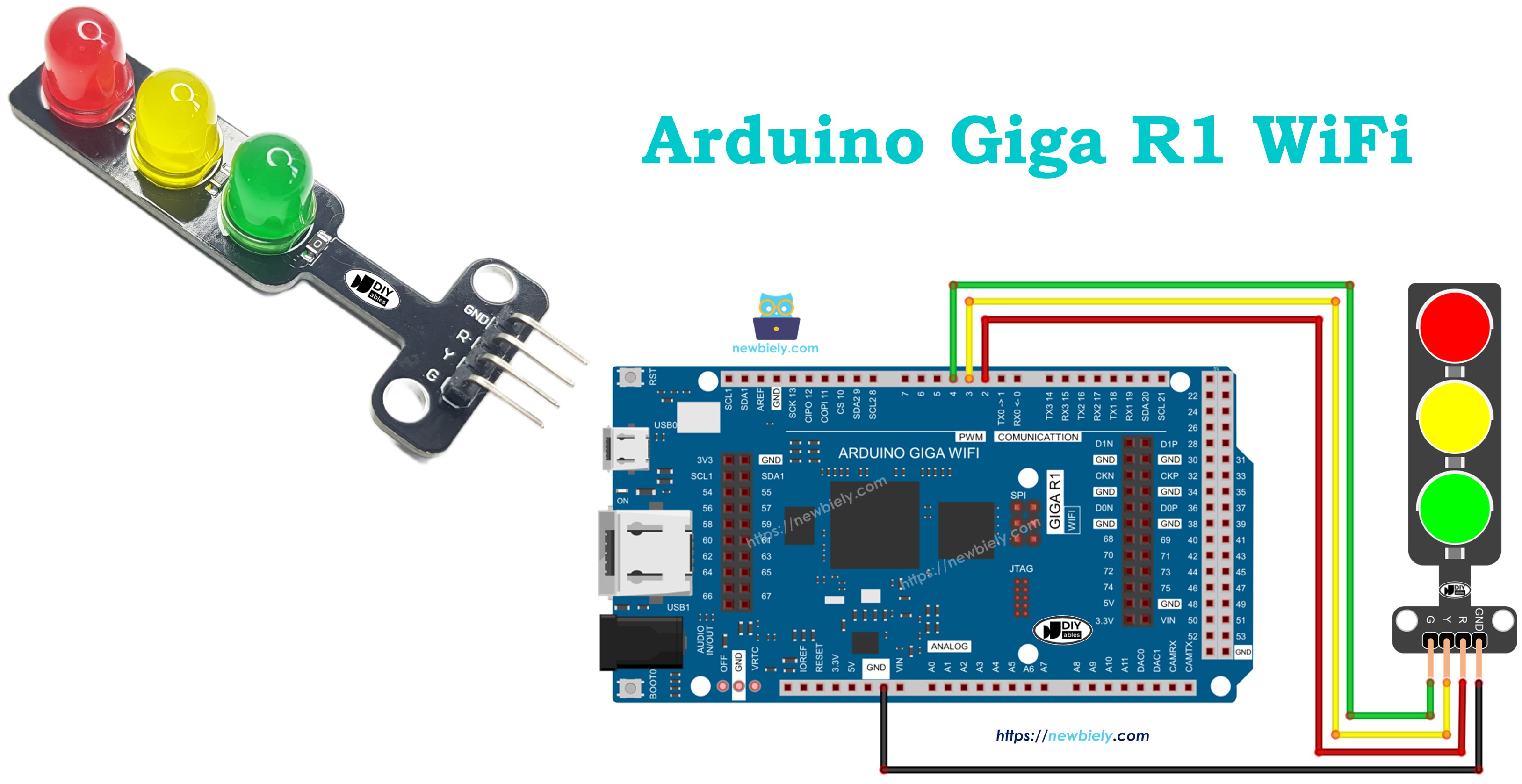
Wiring Diagram
The wiring implementation connects each traffic light control pin to a dedicated Arduino Giga R1 WiFi digital output. This configuration provides independent control of all three LED colors with reliable electrical connections and proper current handling.
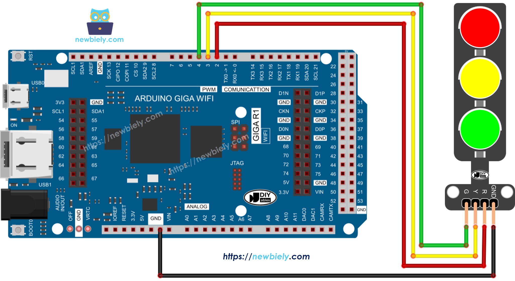
This image is created using Fritzing. Click to enlarge image
Electrical Note: The diagram above shows the minimum viable connection for traffic light control. For production applications or extended operation, consider adding external pull-down resistors (10kΩ) on control lines to ensure defined OFF states during Arduino reset or power-up sequences.
The power supply design draws maximum 60mA when all LEDs are active simultaneously, well within the Arduino Giga R1 WiFi's 5V output capability. The USB power supply typically provides 500mA, leaving substantial margin for additional components or multiple traffic light modules.
| Traffic Light Pin | Arduino Giga R1 WiFi Pin |
|---|---|
| GND | GND |
| R (Red) | Digital Pin 8 |
| Y (Yellow) | Digital Pin 9 |
| G (Green) | Digital Pin 10 |
How To Program For Traffic Light module
The implementation logic centers on configuring Arduino digital pins as outputs and controlling LED states through digitalWrite() operations. The code structure handles traffic sequence timing using either delay() functions for simple applications or millis()-based timing for responsive, non-blocking operation.
The approach uses standard Arduino digital I/O functions to manage three independent LED outputs. Each traffic light color maps to a specific digital pin, configured during setup() and controlled through the main loop logic. Key programming sections include pin initialization, timing control, and sequence state management for realistic traffic patterns.
- Configure Arduino pins as digital outputs using pinMode() function to enable LED current sourcing:
Arduino Code
The following implementation demonstrates basic traffic light control using delay-based timing. The code is structured to handle standard traffic sequences with configurable timing intervals for each state. Key sections include pin definitions, timing constants, and the sequential state machine logic explained inline.
Detailed Instructions
For initial Arduino Giga R1 WiFi setup, refer to the Arduino Giga R1 WiFi Getting Started guide before proceeding with traffic light implementation.
- Connect Hardware: Wire the traffic light module to Arduino pins 8, 9, and 10 according to the wiring diagram. Verify all connections are secure and GND is properly connected to prevent floating voltages.
- Open Arduino IDE: Launch Arduino IDE and ensure the Arduino Giga R1 WiFi board package is selected from Tools > Board menu. Incorrect board selection will cause compilation errors due to different pin definitions.
- Load Code: Copy the traffic light control code and paste into a new Arduino sketch. Verify pin definitions match your physical wiring configuration before proceeding.
- Upload Program: Click the Upload button to compile and transfer code to the Arduino Giga R1 WiFi. Monitor the IDE console for any compilation errors, which typically indicate missing board packages or syntax issues.
- Verify Operation: Observe the traffic light sequence - red (5 seconds), red+yellow (2 seconds), green (5 seconds), yellow (2 seconds), then repeat. Each transition should occur at precise timing intervals without LED flickering.
- Monitor Serial Output: Open the serial monitor at 9600 baud to view state transition messages. The output should show "Red Light", "Red + Yellow Light", "Green Light", "Yellow Light" messages corresponding to each phase.
Technical Note: The basic implementation uses delay() functions which block program execution during timing intervals. For applications requiring sensor input, communication, or multi-tasking capabilities, the millis()-based approach shown in advanced examples provides non-blocking timing control.
It's important to note that the exact workings of a traffic light can vary depending on the specific design and technology used in different regions and intersections. The principles described above provide a general understanding of how traffic lights operate to manage traffic and enhance safety on the roads.
The code above demonstrates individual light control. Now, let's enhance the code for better optimization.
Arduino Code Optimization
Advanced traffic light control implementation improves code maintainability and system responsiveness through function-based design and non-blocking timing techniques. These optimizations enable integration with sensors, communication systems, and multiple traffic signals while maintaining precise timing control.
- Let's improve the code by implementing a function for light control:
- Let's improve the code by using a for loop for sequence management:
- Let's improve the code by using millis() function instead of delay() for non-blocking operation:
The millis()-based implementation provides significant advantages for real-world applications: the system can respond to sensor inputs during timing intervals, handle multiple traffic signals simultaneously, and maintain communication with other devices without timing disruption. This approach is essential for professional automation applications where system responsiveness is critical.
Application Ideas
Intersection Traffic Simulator: Build a complete four-way intersection controller with multiple traffic light modules and pedestrian crossing signals. The Arduino Giga R1 WiFi's dual-core architecture enables simultaneous management of multiple signal phases while handling sensor inputs for vehicle detection and pedestrian requests.
Industrial Process Status Display: Implement traffic light modules as machine status indicators in manufacturing environments. Red indicates fault conditions, yellow shows maintenance required, and green signals normal operation. Integration with the Arduino Giga R1 WiFi's WiFi capability enables remote monitoring and SCADA system integration.
Smart Parking Guidance System: Deploy traffic lights to indicate parking space availability — green for available, yellow for time-limited, red for occupied. The Arduino Giga R1 WiFi's wireless connectivity supports real-time updates to mobile applications and central management systems for large parking facilities.
Educational Traffic Training System: Create scale model intersections for driver education with realistic timing patterns and emergency vehicle preemption. Multiple Arduino Giga R1 WiFi units can network together to simulate coordinated traffic signal systems across educational facilities.
Warehouse Vehicle Management: Control traffic flow in industrial facilities where forklifts and pedestrians share pathways. Integration with proximity sensors and RFID systems enables automatic traffic priority control based on vehicle type and load urgency.
Remote Site Status Monitoring: Deploy weatherproof traffic light assemblies for remote infrastructure monitoring — pump stations, solar installations, or communication towers. The Arduino Giga R1 WiFi's low power modes and wireless connectivity enable long-term deployment with cellular or satellite communication links.
Challenge Yourself
Challenge: Implement emergency vehicle preemption that immediately switches all directions to red when a digital input is activated. Add proper timing delays to ensure safe intersection clearing before returning to normal sequence operation.
Challenge: Create a pedestrian crossing system with button input and audible feedback. Use the Arduino Giga R1 WiFi's second core to handle audio generation while the main core manages traffic timing without interruption.
Challenge: Build a networked intersection system where multiple Arduino Giga R1 WiFi units communicate via WiFi to coordinate green light timing. Implement adaptive timing based on traffic density sensors to optimize flow through the intersection network.
Challenge: Design a traffic light controller with web interface for remote monitoring and manual override. Utilize the Arduino Giga R1 WiFi's WiFi capability to serve configuration pages and log traffic pattern data to SD card storage for traffic engineering analysis.
Challenge: Implement a complete Intelligent Transportation System (ITS) node with vehicle detection sensors, emergency preemption, pedestrian request handling, and communication with traffic management centers. Use both processor cores for real-time signal processing and communication management.