Arduino Giga R1 WiFi Soil Moisture Sensor
This guide covers capacitive soil moisture sensor integration with the Arduino Giga R1 WiFi — from hardware setup to working code. The Arduino Giga R1 WiFi's robust analog-to-digital converter and 12-bit resolution make it an excellent choice for precise soil moisture monitoring applications in agricultural automation, smart gardening systems, and environmental monitoring projects.
Implementing soil moisture sensing on the Arduino Giga R1 WiFi requires understanding capacitive measurement principles and proper sensor calibration techniques. This documentation covers each step in detail, including the critical differences between resistive and capacitive moisture sensors, calibration procedures for different soil types, and threshold determination for automated irrigation systems.
You'll implement a complete moisture monitoring system using a capacitive soil moisture sensor that provides corrosion-resistant, long-term operation. The required hardware includes the Arduino Giga R1 WiFi, a capacitive soil moisture sensor, and basic connection materials. The final implementation will accurately distinguish between wet and dry soil conditions with user-defined thresholds.
This tutorial is structured in four main sections: sensor technology comparison and selection, hardware integration with proper wiring practices, code implementation with calibration procedures, and practical applications for real-world deployment. The Arduino Giga R1 WiFi's expanded memory capacity and dual-core architecture enable advanced features like data logging, wireless reporting, and multi-sensor array management.
Hardware Preparation
Or you can buy the following kits:
| 1 | × | DIYables Sensor Kit (18 sensors/displays) |
Additionally, some of these links are for products from our own brand, DIYables .
Buy Note: Many soil moisture sensors available in the market are unreliable, regardless of their version. We strongly recommend buying the sensor with TLC555I Chip from the DIYables brand using the link provided above. We tested it, and it worked reliably.
Overview of Soil Moisture Sensor
Capacitive soil moisture sensors are electronic measurement devices designed for non-invasive soil water content detection in agricultural and environmental monitoring applications. These sensors operate on capacitive sensing principles, measuring the dielectric constant changes in soil as moisture content varies, providing analog voltage output proportional to water concentration levels.
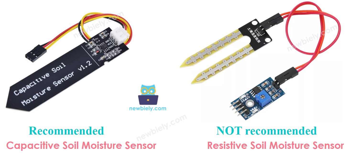
Two primary soil moisture sensor technologies dominate the market: resistive moisture sensors and capacitive moisture sensors. Both sensors provide quantitative soil moisture information through electrical measurement techniques. However, their underlying operating principles, longevity characteristics, and measurement accuracy differ significantly in practical applications.
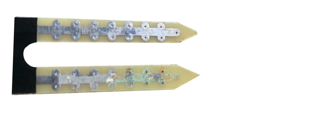
Resistive Moisture Sensors operate by measuring electrical conductivity between two exposed metal probes inserted into soil. As soil moisture increases, ionic conductivity rises, reducing electrical resistance between the probes. However, this direct current flow causes electrochemical corrosion of the metal electrodes over time. The corrosion process degrades measurement accuracy and ultimately destroys the sensor, typically within 6-12 months of continuous operation in soil environments.
Capacitive Moisture Sensors function by detecting changes in the dielectric constant of soil surrounding the sensor's capacitive plates. Unlike resistive sensors, capacitive designs use non-exposed electrodes embedded within a protective substrate, eliminating direct electrical contact with soil. This design approach prevents electrochemical corrosion entirely, enabling multi-year operational lifespans with consistent measurement accuracy.
The capacitive approach offers superior performance characteristics: corrosion immunity, stable long-term calibration, reduced sensitivity to soil salinity variations, and lower power consumption. For Arduino Giga R1 WiFi applications requiring reliable, long-term soil monitoring, capacitive sensors represent the optimal engineering choice.
Operating parameters for typical capacitive soil moisture sensors include: 3.3V to 5V supply voltage compatibility, 0.7V to 3.0V analog output range, 5mA maximum current consumption, and -40°C to +85°C operating temperature range. The measurement accuracy typically ranges from ±3% to ±5% after proper calibration for specific soil compositions.
The below image demonstrates a resistive soil moisture sensor exhibiting severe electrode corrosion after extended field deployment, illustrating the fundamental durability limitations of resistive measurement technology.
The remainder of this tutorial focuses exclusively on capacitive soil moisture sensor implementation with the Arduino Giga R1 WiFi platform.
Capacitive Soil Moisture Sensor Pinout
The pinout defines each physical connection's electrical function and integration requirements. Correct wiring is essential for reliable operation — incorrect power connections may damage the sensor, while signal line errors produce unreliable readings or complete measurement failure.
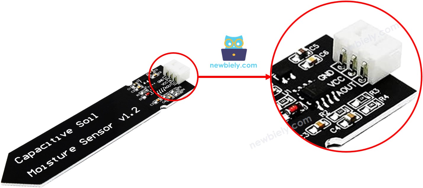
A capacitive soil moisture sensor implements a three-pin interface optimized for microcontroller integration:
GND pin: Ground reference connection, 0V potential. Connects to Arduino Giga R1 WiFi ground plane to establish common electrical reference for all circuit elements.
VCC pin: Power supply input, accepts 3.3V to 5V DC. Connects to Arduino Giga R1 WiFi 5V output to provide sensor operating power. Current consumption typically 5mA maximum during active measurement.
AOUT pin: Analog output signal, 0.7V to 3.0V range. Connects to Arduino Giga R1 WiFi analog input pin (A0-A5) to enable ADC conversion. Output voltage decreases proportionally with increasing soil moisture content.
Signal logic levels follow standard 0-5V conventions compatible with Arduino Giga R1 WiFi analog input specifications. The AOUT pin features high output impedance (typically >10kΩ), requiring minimal input loading from the Arduino's ADC circuitry. No external pull-up or pull-down resistors are required for proper operation.
Common wiring errors include power supply polarity reversal (which may damage the sensor's internal voltage regulator), connecting AOUT to a digital pin instead of an analog input (preventing ADC measurement), and inadequate ground connections causing measurement noise and instability.
How It Works
The capacitive soil moisture sensor operates on dielectric constant measurement principles. Soil composition creates a variable capacitor between the sensor's internal electrodes, where water content directly influences the dielectric properties of the soil medium. As moisture increases, the effective dielectric constant rises, increasing capacitance between the sensor plates.
The sensor's internal oscillator circuit converts capacitance variations into proportional voltage changes on the AOUT pin. Higher soil moisture content produces lower output voltages, creating an inverse relationship between water concentration and measured voltage. This inverse characteristic enables direct threshold-based dry/wet determination logic in software applications.
Temperature compensation circuitry within quality capacitive sensors minimizes thermal drift effects, maintaining measurement stability across typical environmental operating ranges. The measurement principle remains effective across various soil types, though calibration procedures must account for different soil compositions and mineral content variations.
Wiring Diagram
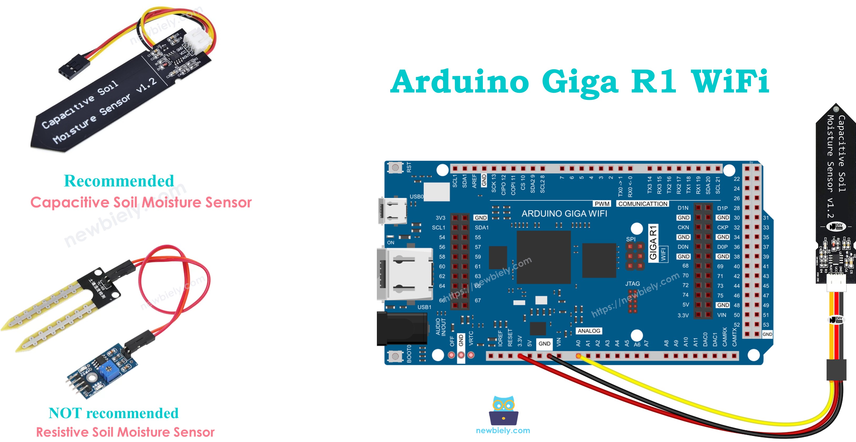
The following wiring configuration demonstrates the standard connection method for integrating a capacitive soil moisture sensor with the Arduino Giga R1 WiFi platform. This implementation uses analog input pin A0 for signal acquisition and provides 5V power supply from the Arduino's regulated output.
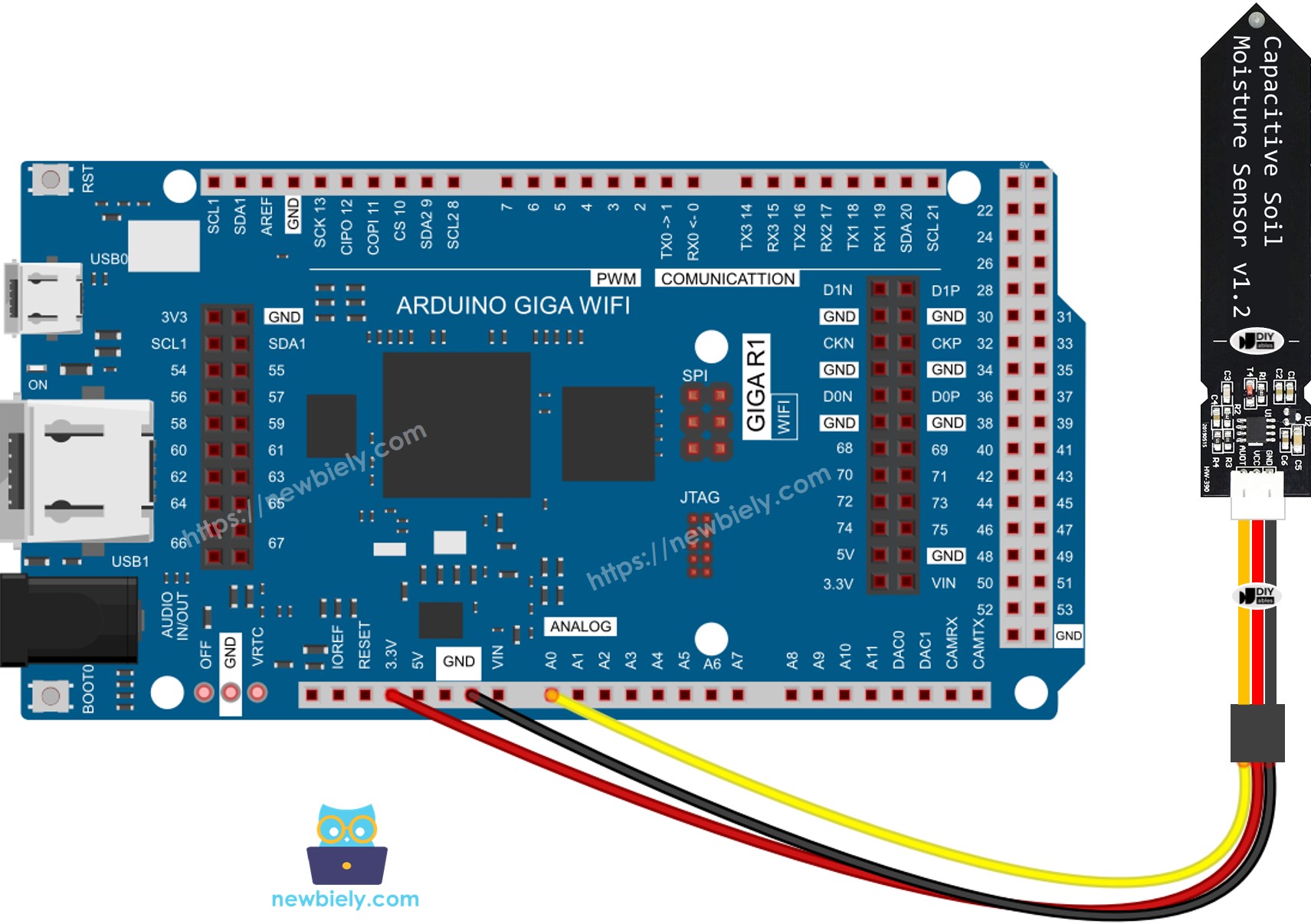
This image is created using Fritzing. Click to enlarge image
Electrical Note: The diagram above shows the minimum viable connection for development and testing purposes. For production deployment or extended outdoor operation, consider adding a 100nF ceramic capacitor between VCC and GND near the sensor to improve power supply decoupling and reduce measurement noise. Additionally, use shielded cable for the AOUT connection if wire runs exceed 1 meter to minimize electromagnetic interference.
Power supply requirements: The capacitive moisture sensor operates reliably from the Arduino Giga R1 WiFi's onboard 5V regulator, which provides up to 500mA current capacity. The sensor's 5mA consumption represents minimal loading on the Arduino's power system, leaving adequate margin for additional sensors or peripherals in multi-device applications.
| Sensor Pin | Arduino Giga R1 WiFi Pin |
|---|---|
| VCC | 5V |
| GND | GND |
| AOUT | A0 (Analog Input) |
Arduino Code Implementation
The following implementation demonstrates analog-to-digital conversion and serial communication techniques for soil moisture measurement. The code is structured to handle continuous sensor polling with 500ms sampling intervals, providing real-time moisture monitoring capabilities. Key sections include ADC configuration, serial output formatting, and timing control for optimal measurement stability.
The analogRead() function utilizes the Arduino Giga R1 WiFi's 12-bit ADC to convert the sensor's analog voltage into digital values ranging from 0 to 4095. This high resolution enables precise moisture level discrimination and accurate threshold detection for automated irrigation control applications.
This basic implementation polls the moisture sensor continuously and outputs raw ADC values to the serial monitor. The 500ms delay provides sufficient time between readings for stable measurements while enabling responsive monitoring of moisture changes during calibration procedures.
Detailed Instructions
Prerequisites: Arduino IDE installed and the Giga R1 WiFi board package configured. Refer to the Getting Started guide for setup instructions if needed.
- Connect Hardware: Wire the capacitive soil moisture sensor to the Arduino Giga R1 WiFi according to the wiring diagram above. Verify VCC connects to 5V, GND to ground, and AOUT to analog pin A0. Double-check connections before applying power to prevent component damage.
- Load Code: Copy the moisture sensor code and open it with Arduino IDE. Verify the board selection shows "Arduino Giga R1 WiFi" and the correct COM port is selected. The code should compile without errors if the board package is properly installed.
- Upload Firmware: Click the Upload button on Arduino IDE to transfer code to the Arduino Giga R1 WiFi. The IDE should display "Done uploading" upon successful completion. If upload fails, verify USB cable connection and board selection settings.
- Prepare Test Setup: Bury the sensor portion in soil, leaving the circuit board above ground level. Never submerge the circuit portion in water or soil as this will damage the electronics. For initial testing, use salt water (not pure water) to simulate moisture changes.
- Monitor Output: Open Serial Monitor in Arduino IDE and set baud rate to 9600. The monitor should display continuous "Moisture: [value]" readings. Values typically range from 400-900 depending on soil type and moisture content. Pour water gradually to observe value changes.
- Verify Operation: As moisture increases, ADC values should decrease consistently. Dry soil produces higher values (typically 600-900), while wet soil generates lower values (typically 400-600). Sudden value changes or constant readings may indicate wiring errors.
Technical Note: The Arduino Giga R1 WiFi's 12-bit ADC provides 4096 discrete measurement levels, offering superior resolution compared to traditional 10-bit Arduino platforms. This enhanced precision enables more accurate threshold determination and improved wet/dry discrimination in challenging soil conditions.
Serial Monitor Output
※ NOTE THAT:
- Do NOT use pure water for testing since it doesn't conduct electricity, which means it won't impact the sensor readings. Use salt water or natural soil with mineral content for accurate moisture detection.
- The sensor readings typically don't drop to zero. It's normal for them to stay within the range of 400 to 900, but this might change based on factors such as how deep the sensor is placed, the type of soil or water, and the voltage of the power supply.
- Never bury the circuit part (found on top of the sensor) in soil or water, as this could harm the sensor and void any warranty coverage.
Calibration for Capacitive Soil Moisture Sensor
Soil moisture sensor calibration is essential for accurate wet/dry determination because measured values are relative to specific soil compositions, mineral content, and environmental conditions. Raw ADC readings vary significantly between different soil types — sandy soil, clay soil, and potting mix each produce different baseline readings and moisture response curves.
The calibration process establishes a threshold value that represents the transition point between dry and wet soil conditions for your specific application. This threshold becomes the decision boundary for automated irrigation systems, plant monitoring applications, and environmental data logging projects.
Calibration Procedure:
The calibration process requires systematic measurement of soil moisture transition points under controlled conditions. This procedure establishes accurate thresholds for reliable wet/dry determination in your specific soil environment.
- Execute Baseline Code: Run the moisture monitoring code provided above on your Arduino Giga R1 WiFi system. Verify stable serial monitor output showing consistent ADC readings before proceeding with calibration measurements.
- Install Sensor: Embed the capacitive moisture sensor into your target soil at the desired monitoring depth. Ensure the sensing portion is fully inserted while keeping the circuit board above ground level. Allow 2-3 minutes for readings to stabilize after installation.
- Establish Dry Baseline: Record several moisture readings from completely dry soil conditions. Calculate the average value — this represents your dry soil baseline for threshold calculation purposes.
- Perform Moisture Addition: Pour water into the soil slowly and gradually, allowing time for water absorption and distribution. Monitor serial output continuously during this process to observe the moisture response curve.
- Identify Transition Point: Watch Serial Monitor readings closely during water addition. Identify the specific ADC value at the moment when soil transitions from visually dry to adequately moist for your application requirements. This value becomes your calibration threshold.
- Document Threshold: Record the transition point value — this is your THRESHOLD constant for wet/dry determination logic. Add a 10-20% safety margin if needed for your specific application requirements.
Determine if the soil is wet or dry
After completing calibration procedures, implement threshold-based wet/dry determination using the established THRESHOLD value. The following code demonstrates conditional logic for soil state classification with clear serial output formatting for monitoring and debugging purposes.
The conditional logic uses greater-than comparison because capacitive moisture sensors produce inverse output — higher ADC values indicate drier soil conditions, while lower values represent increased moisture content. Adjust the THRESHOLD value based on your calibration results and specific application requirements.
Application and Project Ideas
Automated Irrigation Controller: Implement a complete irrigation management system using the soil moisture sensor to trigger water pumps or solenoid valves. The Arduino Giga R1 WiFi's dual-core architecture enables simultaneous sensor monitoring and pump control with precise timing control for optimal plant care.
Smart Garden Monitoring Station: Create a comprehensive plant monitoring system that logs soil moisture data alongside temperature and humidity sensors. The Arduino Giga R1 WiFi's expanded memory capacity supports extensive data logging with timestamps, while WiFi connectivity enables remote monitoring through web dashboards.
Agricultural Field Sensor Network: Deploy multiple soil moisture sensors across farming areas using the Arduino Giga R1 WiFi as a central data collection hub. The platform's processing power handles multiple sensor inputs simultaneously, aggregating data for transmission to farm management systems via wireless protocols.
Greenhouse Environmental Control: Integrate soil moisture sensing with HVAC control systems for optimal growing conditions. The Arduino Giga R1 WiFi's real-time capabilities enable responsive environmental adjustments based on soil moisture trends, maintaining ideal conditions for commercial plant production.
Research Data Collection Platform: Build scientific data logging systems for soil science research and environmental studies. The Arduino Giga R1 WiFi's precision ADC and computational capabilities support advanced statistical analysis and correlation studies between soil moisture and other environmental parameters.
Indoor Plant Care Assistant: Develop intelligent plant care systems for home and office environments. The Arduino Giga R1 WiFi's connectivity features enable smartphone notifications when plants require watering, with historical moisture trend analysis for optimal care scheduling.
Video Section
The accompanying video demonstrates the complete hardware assembly process and live code execution for soil moisture sensor integration. It covers sensor installation techniques in different soil types, calibration procedures with real-time threshold determination, and troubleshooting common wiring issues that may affect measurement accuracy and system reliability.
Challenge Yourself
Challenge: Implement multi-level moisture classification beyond simple wet/dry states. Create four moisture categories (Very Dry, Dry, Moist, Wet) using multiple threshold values, enabling more precise irrigation control and plant care optimization.
Challenge: Add data logging capabilities using the Arduino Giga R1 WiFi's expanded memory to store hourly moisture readings with timestamps. Implement circular buffer management to maintain 30 days of historical data for trend analysis and irrigation pattern optimization.
Challenge: Create a wireless moisture monitoring network by implementing WiFi connectivity to transmit sensor data to a remote server or cloud platform. Use the Arduino Giga R1 WiFi's built-in WiFi module to enable real-time monitoring from mobile devices or web browsers.
Challenge: Develop an adaptive threshold system that automatically adjusts wet/dry boundaries based on seasonal moisture patterns and plant growth stages. Implement machine learning algorithms using the dual-core processing capabilities for intelligent irrigation scheduling.
Challenge: Build a complete smart irrigation system incorporating soil moisture sensors, weather API integration, and pump control logic. Use the Arduino Giga R1 WiFi's processing power to analyze weather forecasts and adjust irrigation schedules based on predicted rainfall and temperature conditions.