Arduino Giga R1 WiFi Touch Sensor
This guide covers capacitive touch sensor implementation with the Arduino Giga R1 WiFi — from hardware connections to working code examples. Touch sensors (also called touch buttons or touch switches) provide the same digital input functionality as mechanical buttons while offering several engineering advantages: no mechanical wear, sealed construction for harsh environments, and modern aesthetic appeal.
The Arduino Giga R1 WiFi's robust digital input capabilities and dual-core architecture make it excellent for touch sensor applications requiring fast response times or concurrent processing. This tutorial implements four distinct touch sensor configurations, from basic digital reading to advanced toggle functionality with edge detection algorithms.
Touch sensors are widely deployed in consumer electronics (touchable lamps, appliances), industrial control panels, automotive interfaces, and IoT devices where reliability and weather resistance are critical. The capacitive sensing technology responds to finger proximity by detecting changes in electrical capacitance, eliminating the mechanical failure points of traditional switches.
This documentation covers complete implementation details: electrical connections, signal timing characteristics, debouncing considerations, and multiple code examples progressing from simple polling to interrupt-driven state machines. Each section includes troubleshooting guidance and real-world application context.
Hardware Preparation
Or you can buy the following kits:
| 1 | × | DIYables Sensor Kit (18 sensors/displays) |
Additionally, some of these links are for products from our own brand, DIYables .
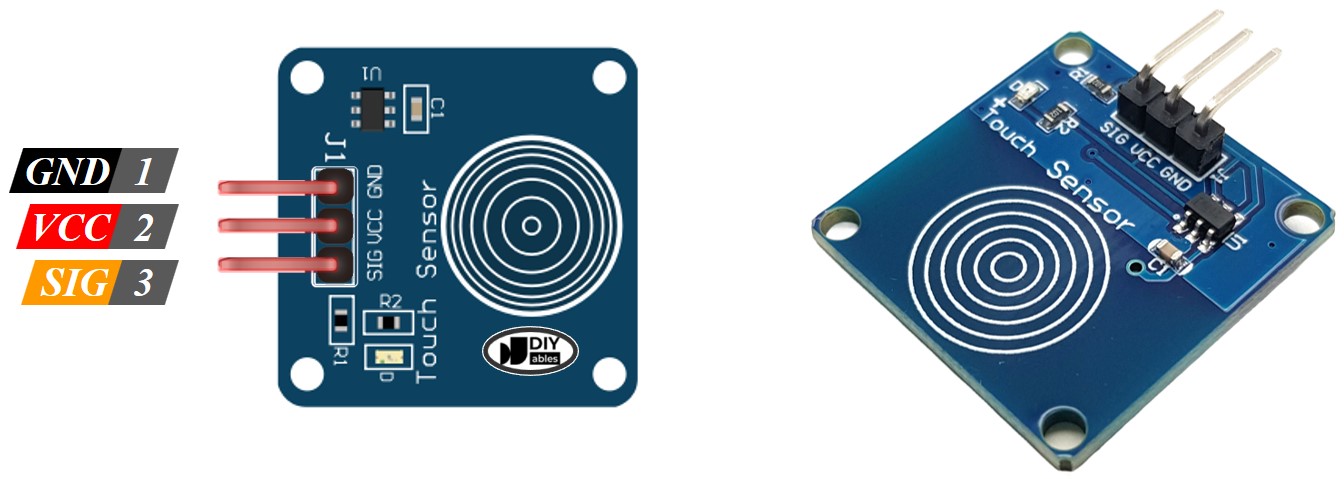
Overview of Touch Sensor
Touch sensors are capacitive detection devices designed for human interface applications. These sensors operate by measuring changes in electrical field capacitance when a conductive object (finger) approaches the sensing pad. Unlike mechanical switches, touch sensors have no moving parts, providing unlimited operational cycles and consistent performance across temperature ranges.
The underlying operating principle relies on capacitive coupling between the sensor electrode and ground reference. When a finger touches or approaches the sensing surface, it introduces additional capacitance to ground, shifting the sensor's oscillator frequency. Internal comparator circuits detect this frequency change and assert a digital output signal.
Modern touch sensors integrate signal conditioning, noise filtering, and hysteresis to provide clean digital outputs suitable for microcontroller interfacing. Typical sensitivity ranges from direct contact to several millimeters proximity, depending on sensor design and calibration. The Arduino Giga R1 WiFi's 3.3V I/O compatibility ensures reliable signal levels with most commercial touch sensor modules.
Touch sensors offer significant advantages over mechanical switches in applications requiring weather sealing, high reliability, or aesthetic considerations. Common alternatives include mechanical tactile switches (lower cost, tactile feedback) and proximity sensors (greater detection range, higher cost). For Arduino Giga R1 WiFi integration, touch sensors provide an optimal balance of simplicity, reliability, and cost-effectiveness.
Pinout
The pinout defines the electrical interface between the touch sensor and Arduino Giga R1 WiFi. Correct wiring is essential — an incorrect connection may damage the sensor or produce unreliable readings. Touch sensor modules typically use a three-pin configuration optimized for microcontroller interfacing.
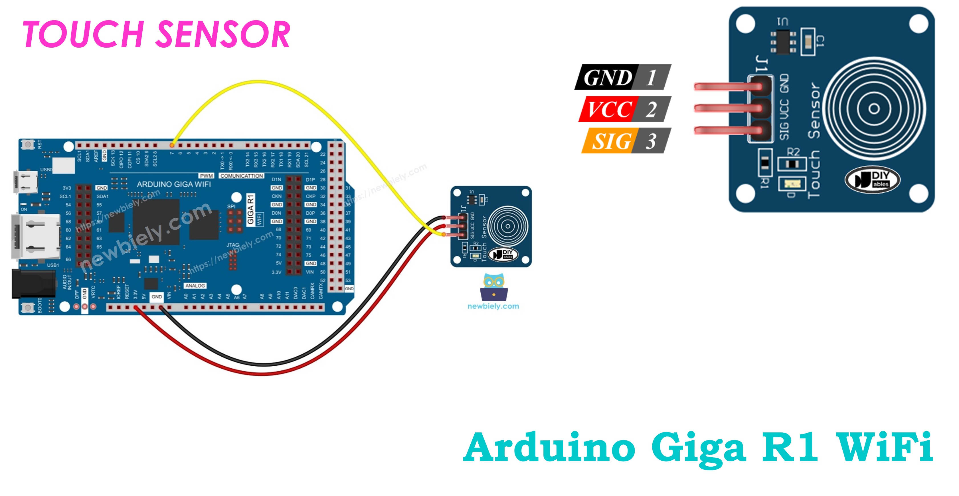
Touch sensor has 3 pins:
- GND pin: Ground reference connection (0V). Connects to Arduino Giga R1 WiFi ground to establish common reference potential. This connection carries return current and must be low-impedance.
- VCC pin: Power supply input (3.3V or 5V). Connects to Arduino regulated power output to supply sensor electronics. Current consumption typically 1-5mA during operation.
- SIGNAL pin: Digital output signal (3.3V logic levels). Connects to Arduino digital input pin to provide touch state information. Output is LOW (0V) when untouched, HIGH (3.3V) when touched. Signal includes integrated pull-down for clean logic transitions.
Signal logic levels are CMOS-compatible with the Arduino Giga R1 WiFi's 3.3V I/O standards. The sensor output includes sufficient drive capability for direct connection without external buffering. Internal debouncing provides stable output during touch transitions, though software debouncing may be required for critical applications.
Common wiring errors include reversed power connections (VCC/GND swap) which may damage the sensor, or connecting the signal pin to Arduino power pins which can damage the microcontroller. Always verify connections against the pinout diagram before applying power.
How It Works
Touch sensor operation is based on capacitive field detection. The sensor generates a low-frequency oscillating electric field around the sensing electrode. When a conductive object (human finger) approaches this field, it alters the capacitive coupling between the electrode and ground reference.
- When the sensor is NOT touched, the sensor's SIGNAL pin is LOW (0V)
- When the sensor is touched, the sensor's SIGNAL pin is HIGH (3.3V)
Internal circuitry continuously monitors this capacitive change through frequency shift detection or charge transfer measurement. When the capacitance exceeds a calibrated threshold, the output comparator switches from LOW to HIGH state. Built-in hysteresis prevents oscillation at the switching threshold.
Response time is typically 100-200 milliseconds from initial touch to stable output assertion. This delay includes internal signal processing, noise filtering, and debouncing algorithms. For applications requiring faster response, the Arduino Giga R1 WiFi's dual-core architecture enables dedicated touch processing on the secondary core.
Arduino - Touch Sensor
The touch sensor's SIGNAL pin connects to any Arduino Giga R1 WiFi digital input pin. The Arduino's internal input conditioning provides additional noise immunity and ESD protection for reliable operation in electromagnetic environments.
By reading the state of Arduino's pin (configured as an input pin), we can detect whether the touch sensor is touched or not. The Arduino Giga R1 WiFi's advanced GPIO capabilities support both polling and interrupt-driven touch detection, enabling efficient processor utilization in multi-tasking applications.
Input pin configuration options include internal pull-up enablement (INPUT_PULLUP mode) for applications requiring additional noise immunity, though most touch sensor modules include integrated pull-down circuitry making external pulls unnecessary.
Wiring Diagram
The following diagram illustrates the standard connection method for integrating a capacitive touch sensor with the Arduino Giga R1 WiFi. This configuration provides the minimum viable connection for development and prototyping applications.
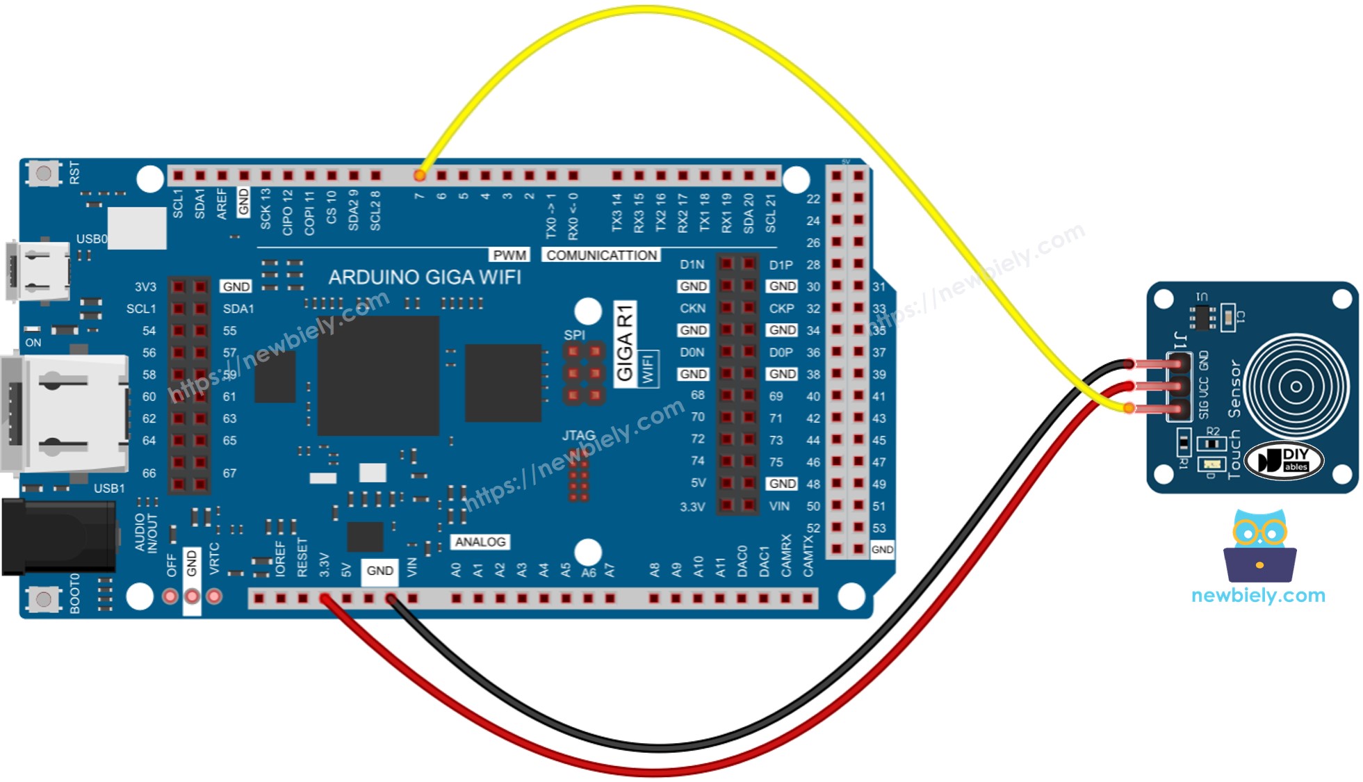
This image is created using Fritzing. Click to enlarge image
Electrical Note: The diagram above shows the minimum viable connection. For production or extended use, consider adding a 100nF ceramic capacitor between VCC and GND pins near the sensor to improve power supply noise immunity. Additionally, keep signal wires short (under 15cm) to minimize EMI pickup that could cause false triggering.
The touch sensor operates from the Arduino's regulated 5V supply, providing optimal sensitivity and noise margin. Ground connection establishes the reference potential for capacitive sensing. Signal wire routing should avoid proximity to switching circuits or PWM outputs that could introduce interference.
| Touch Sensor Pin | Arduino Giga R1 WiFi Pin |
|---|---|
| VCC | 5V |
| GND | GND |
| SIGNAL | Digital Pin 7 |
Power supply requirements: 5V DC, 1-5mA typical consumption. The Arduino Giga R1 WiFi's onboard voltage regulator provides sufficient current capacity for multiple touch sensors in array configurations. Decoupling capacitors (100nF ceramic) should be placed close to the sensor VCC pin for optimal performance in electrically noisy environments.
How To Program For Touch Sensor
The following implementation demonstrates polling-based touch detection using Arduino's standard digital I/O functions. The code is structured to handle both immediate state reading and edge detection for applications requiring touch event processing. Key sections include pin initialization, state reading, and edge detection algorithms.
Touch sensor programming utilizes the Arduino's digitalRead() function to sample the sensor's output state. This approach provides reliable detection with minimal processor overhead. The Arduino Giga R1 WiFi's 48MHz ARM Cortex-M4 processor enables high-frequency polling without impacting system performance.
Two fundamental programming patterns are commonly used: direct state monitoring (immediate response to touch state) and edge detection (response to touch state changes). Selection depends on application requirements - direct monitoring for applications like LED control, edge detection for counting or toggle operations.
- Initialize the Arduino pin to digital input mode using pinMode() function. For example, pin 7:
- Read the state of the Arduino pin using digitalRead() function:
※ NOTE THAT:
There are two widely-used implementation patterns:
- Direct State Monitoring: If the input state is HIGH, execute one action. If the input state is LOW, execute a different action. This pattern provides immediate response to touch state.
- Edge Detection: If the input state changes from LOW to HIGH (or HIGH to LOW), execute an action. This pattern responds to touch events rather than continuous state.
Application selection criteria:
- For LED control where the LED should be ON when touched and OFF when released, use direct state monitoring.
- For toggle functionality where each touch cycles between ON/OFF states, use edge detection.
Edge detection requires state memory (previous reading storage) and comparison logic to identify transitions. This approach prevents multiple triggers from a single touch event.
- Edge detection implementation for LOW to HIGH transition:
This edge detection algorithm samples the touch sensor each loop iteration, comparing current reading against the previously stored state. When a LOW-to-HIGH transition is detected, it triggers the event handler. The lastState variable maintains state memory between loop cycles, enabling transition detection.
Touch Sensor - Arduino Code
The following implementations demonstrate four progressive touch sensor applications with the Arduino Giga R1 WiFi. Each example builds upon previous concepts, advancing from basic digital reading through sophisticated toggle control with debouncing. These examples cover the most common touch sensor use cases in embedded systems development.
Code examples are structured for educational clarity and practical implementation. The Arduino Giga R1 WiFi's architecture supports all demonstrated techniques with excellent performance characteristics. Library dependencies are minimal, using only standard Arduino functions for maximum compatibility.
We will implement four example applications:
- Basic Reading: Polls touch sensor state and outputs to Serial Monitor for debugging and verification
- Direct LED Control: Controls onboard LED according to instantaneous touch sensor state
- Touch Event Detection: Identifies touch and release events using edge detection algorithms
- Toggle LED Control: Implements sophisticated state machine for LED toggle functionality (most commonly deployed)
Each implementation includes detailed inline documentation, performance considerations, and troubleshooting guidance. Examples progress from fundamental concepts to production-ready implementations suitable for integration into larger systems.
Reads the value from the touch sensor and print to the Serial Monitor
This implementation polls the touch sensor continuously and outputs the digital state to the Arduino IDE Serial Monitor. This approach is essential for initial testing, sensor characterization, and debugging connectivity issues. The continuous output allows observation of sensor behavior, response timing, and noise characteristics.
Detailed Instructions
For initial Arduino Giga R1 WiFi setup, refer to the Arduino Giga R1 WiFi Getting Started guide before proceeding.
- Connect Hardware: Wire the touch sensor to Arduino Giga R1 WiFi according to the wiring diagram. Verify VCC connects to 5V, GND connects to ground, and SIGNAL connects to digital pin 7.
- Open Arduino IDE: Launch Arduino IDE and ensure the Arduino Giga R1 WiFi board is selected under Tools > Board. Verify the correct COM port is selected.
- Load Code: Copy the above code and paste into a new Arduino IDE sketch. The code configures pin 7 as input and continuously reads the sensor state.
- Upload Firmware: Click Upload button to compile and transfer code to Arduino Giga R1 WiFi. Monitor the status bar for successful upload confirmation.
- Open Serial Monitor: Navigate to Tools > Serial Monitor or press Ctrl+Shift+M. Set baud rate to 9600 to match code configuration.
- Test Touch Response: Touch finger to sensor surface and observe output transition from 0 to 1. Release finger and verify return to 0 state.
- Verify Timing: Note the response delay between physical touch and serial output change - typically 100-200ms due to internal sensor processing.
Technical Note: The continuous polling approach consumes minimal processor resources on the Arduino Giga R1 WiFi's ARM Cortex-M4. For battery-powered applications, consider implementing interrupt-driven detection or sleep modes between readings to reduce power consumption.
Controls LED according to the sensor's state
This implementation demonstrates direct state mapping between touch sensor input and LED output. When sensor detects touch (HIGH state), the onboard LED illuminates. When touch is removed (LOW state), LED extinguishes. This pattern is fundamental for applications requiring immediate visual feedback or appliance control.
Detailed Instructions
Ensure the Arduino IDE is configured for the Arduino Giga R1 WiFi before following these steps. See the Getting Started guide if needed.
- Load Configuration: Copy the above code into Arduino IDE. This implementation adds LED_BUILTIN configuration and direct state transfer from sensor to LED output.
- Upload Code: Click Upload button to transfer the firmware. The Arduino Giga R1 WiFi will restart automatically after successful upload.
- Test Direct Control: Touch finger to sensor pad and maintain contact. The onboard LED should illuminate immediately, demonstrating direct state mapping.
- Verify LED Response: LED should remain ON while finger maintains contact with sensor surface. Visual feedback confirms proper electrical connection and code operation.
- Test Release Response: Remove finger from sensor surface. LED should extinguish within 100-200ms, matching sensor response timing.
- Check for False Triggers: Observe LED behavior without touching sensor. Steady OFF state indicates proper wiring and absence of electrical interference.
Technical Note: This direct mapping approach provides zero-latency response between touch detection and LED control. The Arduino Giga R1 WiFi's digital I/O can drive the onboard LED directly without external buffering. For driving higher-current loads, implement transistor switching or relay control interfaces.
Detects the sensor is touched or released
This implementation uses edge detection algorithms to identify touch and release events rather than continuous state monitoring. The state machine compares current sensor reading against the previous reading, triggering event handlers only when transitions occur. This approach is essential for counting applications, event logging, or user interface implementations requiring distinct touch events.
Detailed Instructions
Prerequisites: Arduino IDE installed and the Giga R1 WiFi board package configured. Refer to the Getting Started guide for setup instructions.
- Implement Edge Detection: Load the code into Arduino IDE. This implementation introduces state memory (lastState variable) and transition detection logic.
- Upload and Monitor: Upload code and open Serial Monitor at 9600 baud. The system now responds to state transitions rather than continuous state.
- Test Touch Event: Touch finger to sensor surface. Serial Monitor should display "The sensor is touched" exactly once per touch initiation.
- Maintain Contact: Keep finger on sensor surface. No additional messages should appear, confirming event-based operation rather than continuous polling output.
- Test Release Event: Remove finger from sensor. Serial Monitor should display "The sensor is released" confirming detection of HIGH-to-LOW transition.
- Verify Event Isolation: Perform multiple touch/release cycles. Each physical touch should generate exactly one touch message and one release message.
- Check for Bounce: If multiple events appear for single touches, sensor may exhibit mechanical bounce requiring software debouncing implementation.
Technical Note: Edge detection algorithms prevent event flooding in user interfaces and enable accurate touch counting. The Arduino Giga R1 WiFi's processing speed enables bounce detection and filtering for sensors with mechanical contact elements. For applications requiring precise timing, consider interrupt-driven implementations using attachInterrupt() functions.
Toggles LED when the sensor is touched
This implementation demonstrates a sophisticated state machine combining edge detection with toggle logic. Each touch event alternates the LED between ON and OFF states, simulating push-button toggle switches commonly found in consumer electronics. This pattern is the most frequently deployed touch sensor application in embedded systems.
Detailed Instructions
For initial Arduino Giga R1 WiFi setup, refer to the Arduino Giga R1 WiFi Getting Started guide before proceeding.
- Load Toggle Implementation: Copy the complete code into Arduino IDE. This version combines edge detection with LED state memory for toggle functionality.
- Upload Advanced Code: Transfer firmware to Arduino Giga R1 WiFi. The system now maintains LED state independently of sensor state.
- Test First Toggle: Touch sensor briefly and release. LED should turn ON and remain ON after finger removal, demonstrating state memory operation.
- Verify State Persistence: LED should maintain ON state indefinitely without additional touches, confirming proper state variable implementation.
- Test Second Toggle: Touch sensor again briefly. LED should turn OFF and remain OFF, completing the toggle cycle.
- Repeat Toggle Sequence: Continue touching sensor repeatedly. LED should alternate between ON and OFF states with each touch event.
- Verify Single-Touch Response: Each physical touch should generate exactly one toggle event, regardless of contact duration.
Technical Note: Toggle state machines require three state variables: current sensor reading, previous sensor reading, and output device state. This implementation can be extended to control external relays, motors, or communication interfaces. The Arduino Giga R1 WiFi's dual-core architecture enables complex toggle sequences with timing constraints or multi-device coordination.
Application Ideas
Touch sensor integration with Arduino Giga R1 WiFi enables diverse applications across industrial automation, consumer electronics, and IoT deployments. The following applications leverage the Arduino's processing capabilities and connectivity features for comprehensive system implementations.
Smart Home Lighting Control: Implement capacitive touch switches for wall-mounted lighting control with WiFi connectivity. The Arduino Giga R1 WiFi's wireless capabilities enable integration with home automation systems like Home Assistant or Amazon Alexa. Multiple touch sensors create scene control interfaces with programmable lighting sequences.
Industrial Control Panel Interface: Deploy touch sensors in harsh industrial environments where mechanical switches fail due to contamination or vibration. The Arduino Giga R1 WiFi's robust I/O and dual-core processing enables real-time control with data logging to cloud services. Sealed touch sensors provide IP65+ environmental protection.
IoT Device Wake/Sleep Control: Use touch sensors as power management interfaces for battery-powered IoT devices. The Arduino Giga R1 WiFi's low-power modes combined with interrupt-driven touch detection extend battery life while maintaining user interface responsiveness. Touch events can trigger WiFi connection and data transmission cycles.
Appliance User Interface: Integrate touch sensors into kitchen appliances, HVAC controls, or automotive interfaces requiring modern aesthetics and reliability. The Arduino's processing power enables multi-touch gesture recognition and haptic feedback control via PWM outputs.
Access Control System: Implement secure touch-based entry systems with RFID integration and wireless monitoring. The Arduino Giga R1 WiFi's connectivity enables real-time access logging, remote monitoring, and integration with building management systems.
Equipment Maintenance Interface: Deploy touch sensors for equipment calibration, diagnostic access, or safety interlocks in manufacturing environments. Data logging capabilities enable maintenance scheduling and usage analytics through cloud connectivity.
Video Section
The accompanying video demonstrates the complete hardware assembly process and live code execution with the Arduino Giga R1 WiFi and capacitive touch sensor. It covers proper wiring techniques to avoid common connection errors, shows expected serial monitor output for each code example, and demonstrates the timing characteristics of touch detection and release events.
Challenge Yourself
Advanced touch sensor implementations provide opportunities to explore the Arduino Giga R1 WiFi's full capabilities while developing practical embedded systems skills. These challenges progress from basic modifications to complete system development.
Challenge: Implement touch sensor debouncing with adjustable timing thresholds. Add a potentiometer to control the debounce delay from 10-500ms, enabling optimization for different sensor types and environmental conditions.
Challenge: Create a multi-touch sensor array using 4-6 touch sensors connected to different digital pins. Implement pattern recognition to detect specific touch sequences (like security codes) and trigger different responses based on the detected pattern.
Challenge: Develop a WiFi-enabled touch sensor monitoring system that logs all touch events to a web server with timestamps. Use the Arduino Giga R1 WiFi's wireless connectivity to create a REST API endpoint that reports sensor status and historical touch data.
Challenge: Build a touch-sensitive smart switch with over-the-air firmware updates and remote configuration. Implement a web interface for setting touch sensitivity, toggle behavior, and scheduling automatic operation modes.
Challenge: Design a dual-core implementation where one core handles touch sensor processing with interrupt-driven edge detection while the second core manages WiFi communication and data logging. Implement inter-core communication to share sensor events and system status.