Arduino Giga R1 WiFi Water/Liquid Valve
This guide covers liquid flow control with the Arduino Giga R1 WiFi and solenoid valves — from hardware setup to working code. The implementation demonstrates precise valve control for water, oil, beer, or any fluid requiring automated flow management.
The Arduino Giga R1 WiFi's robust GPIO capabilities and dual-core STM32H747XI processor make it an excellent choice for industrial automation and fluid control applications. This tutorial walks through the complete implementation using a 12V solenoid valve controlled via relay switching, providing the foundation for automated irrigation systems, beverage dispensing, chemical processing, and manufacturing applications.
Implementing reliable liquid valve control requires understanding both the electrical characteristics of solenoid valves and proper relay isolation techniques. The solenoid valve operates as an electromagnetic actuator that opens or closes a flow path when energized, while the relay provides electrical isolation between the Arduino's 3.3V logic levels and the valve's 12V operating voltage. This configuration ensures safe, reliable operation while protecting the microcontroller from inductive kickback.
This documentation covers hardware selection, wiring implementation, safety considerations, and practical code examples. You'll implement a complete valve control system capable of precise timing control, suitable for integration into larger automation systems or as a standalone flow controller.
Hardware Preparation
Or you can buy the following kits:
| 1 | × | DIYables Sensor Kit (18 sensors/displays) |
Additionally, some of these links are for products from our own brand, DIYables .
Overview of Water/Liquid Valve
Liquid solenoid valves are electromagnetic actuators designed for automated flow control in fluid systems. These devices consist of a coil, plunger, spring mechanism, and valve seat arrangement that provides reliable on/off control of liquid flow. When energized, the electromagnetic coil creates a magnetic field that overcomes the spring force, lifting the plunger and opening the flow path.
The operating principle relies on electromagnetic force generation. When 12V DC is applied across the coil terminals, the resulting magnetic field magnetizes the plunger core, creating an attractive force toward the coil center. This force overcomes the spring preload, lifting the plunger and unseating the valve mechanism. When power is removed, the spring force returns the plunger to its closed position, sealing the flow path.
Typical solenoid valves operate with electrical specifications including 12V DC nominal voltage (±10%), current draw ranging from 200mA to 2A depending on valve size, and response times of 10-50 milliseconds for opening and closing cycles. Flow capacity ranges from fractional GPM for small valves up to several hundred GPM for industrial applications. Operating pressure ranges typically span 0-150 PSI for standard configurations.
Integration with the Arduino Giga R1 WiFi requires relay-based isolation due to the voltage and current requirements exceeding the microcontroller's direct drive capability. The Arduino's GPIO pins operate at 3.3V logic levels with maximum source current of 25mA, insufficient for direct solenoid valve control. A relay module provides the necessary voltage translation and current amplification while maintaining electrical isolation.
Pinout
The pinout maps each physical connection to its electrical function. Correct wiring is essential — an incorrect connection may damage components or produce unreliable valve operation. Reversed polarity connections can damage the Arduino or create safety hazards in pressurized systems.
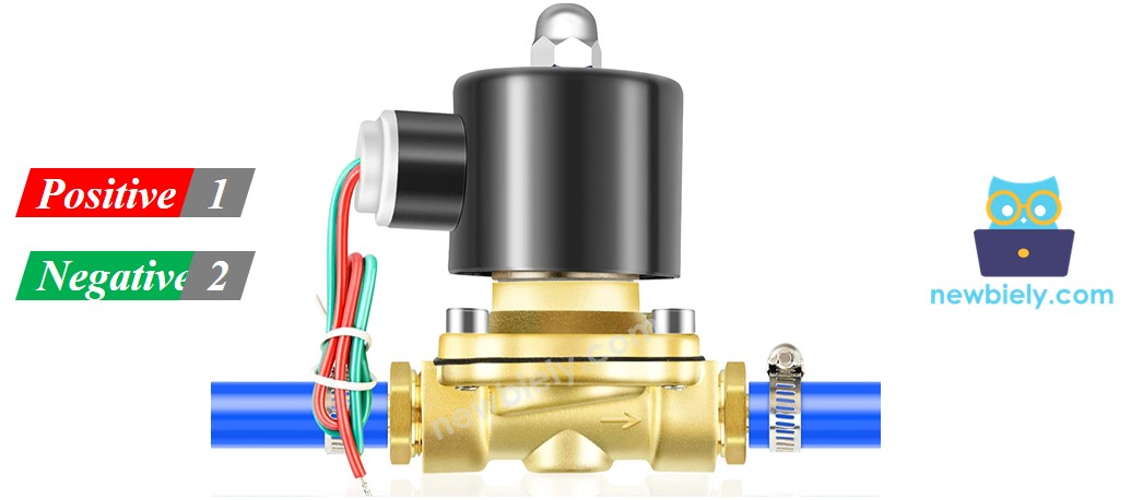
Solenoid valves typically feature two main electrical terminals:
Positive (+) Terminal (Red Wire): 12V DC supply input, 200mA-2A current depending on valve specifications. Connects to relay normally-open contact to enable Arduino switching control. Requires stable DC voltage within ±5% for reliable operation.
Negative (-) Terminal (Black/Blue Wire): Ground return path to DC power supply negative terminal. Must maintain low-resistance connection to prevent voltage drop and ensure proper coil energization. Current capacity must match positive terminal specifications.
Signal logic levels require 12V DC for valve activation (ON state) and 0V for deactivation (OFF state). The coil presents an inductive load that generates back-EMF during switching transitions. Proper relay selection with flyback diode protection prevents damage from inductive voltage spikes.
Common wiring errors include reversed polarity (which may damage valve coil), inadequate wire gauge for current requirements (causing voltage drop), and missing flyback protection (causing relay contact arcing). Always verify polarity before applying power and use appropriately rated wire gauge for the valve's current specification.
How Water/Liquid Valve works
The solenoid valve operates through electromagnetic actuation of a spring-loaded plunger mechanism. In the de-energized state (12V not applied), the spring force maintains the plunger in the closed position, sealing the valve seat and blocking liquid flow. The valve remains normally closed, preventing flow regardless of inlet pressure up to the valve's maximum rated pressure.
When 12V DC is applied to the coil terminals, the electromagnetic field generates sufficient magnetic force to overcome the spring preload plus any differential pressure force. The plunger lifts from the valve seat, creating a flow path through the valve body. Flow capacity depends on the valve orifice diameter, inlet pressure, and fluid viscosity.
The electromagnetic response time is typically 10-50 milliseconds for valve opening, determined by the coil inductance, applied voltage, and mechanical inertia. Closing response time is generally faster (5-20 milliseconds) since it relies only on spring force and does not require magnetic field buildup.
※ NOTE THAT:
- For some kinds of valve, there is a gasket arrangement inside, so there is a minimum pressure requires to open the valve (after 12V DC is applied). The pressure can be created by liquid flow.
- For some kinds of valve, liquid can only flow one direction.
- Pilot-operated valves may require minimum pressure differential (typically 3-5 PSI) to achieve full opening even when electrically energized.
- Direct-acting valves can open against zero pressure differential but have lower flow capacity than pilot-operated designs.
- Valve orientation affects performance — some designs require horizontal mounting while others can operate in any orientation.
- Operating temperature range typically spans -10°C to +80°C, with seal materials determining upper temperature limits.
How to Control Water/Liquid Solenoid Valve
Controlling liquid solenoid valves with the Arduino Giga R1 WiFi requires relay-based isolation due to the voltage and current mismatch between the microcontroller and valve specifications. The Arduino operates at 3.3V logic levels with maximum GPIO current of 25mA, while solenoid valves require 12V DC at currents ranging from 200mA to 2A.
The control architecture uses a relay module as an electrically isolated switch. The Arduino GPIO pin controls the relay coil (typically requiring 15-20mA at 3.3V), which actuates relay contacts capable of switching the 12V valve supply. This configuration provides complete electrical isolation between the low-voltage control circuit and high-current valve circuit.
Relay selection requires consideration of contact ratings, coil voltage compatibility, and switching speed. Choose relays with contact ratings exceeding the valve current by at least 50% safety margin. For example, a 1A solenoid valve should use a relay rated for minimum 1.5A contact current. The relay coil must operate reliably from 3.3V Arduino GPIO output to ensure consistent switching.
Timing considerations include relay switching delay (typically 5-15 milliseconds) plus valve response time (10-50 milliseconds). Total system response from Arduino command to full valve opening ranges from 15-65 milliseconds depending on component specifications. For precise timing applications, account for these delays in software implementation.
If you do not know about relay operation, electrical characteristics, pinout identification, or programming techniques, learn about relay fundamentals in the Arduino - Relay tutorial before proceeding with valve control implementation.
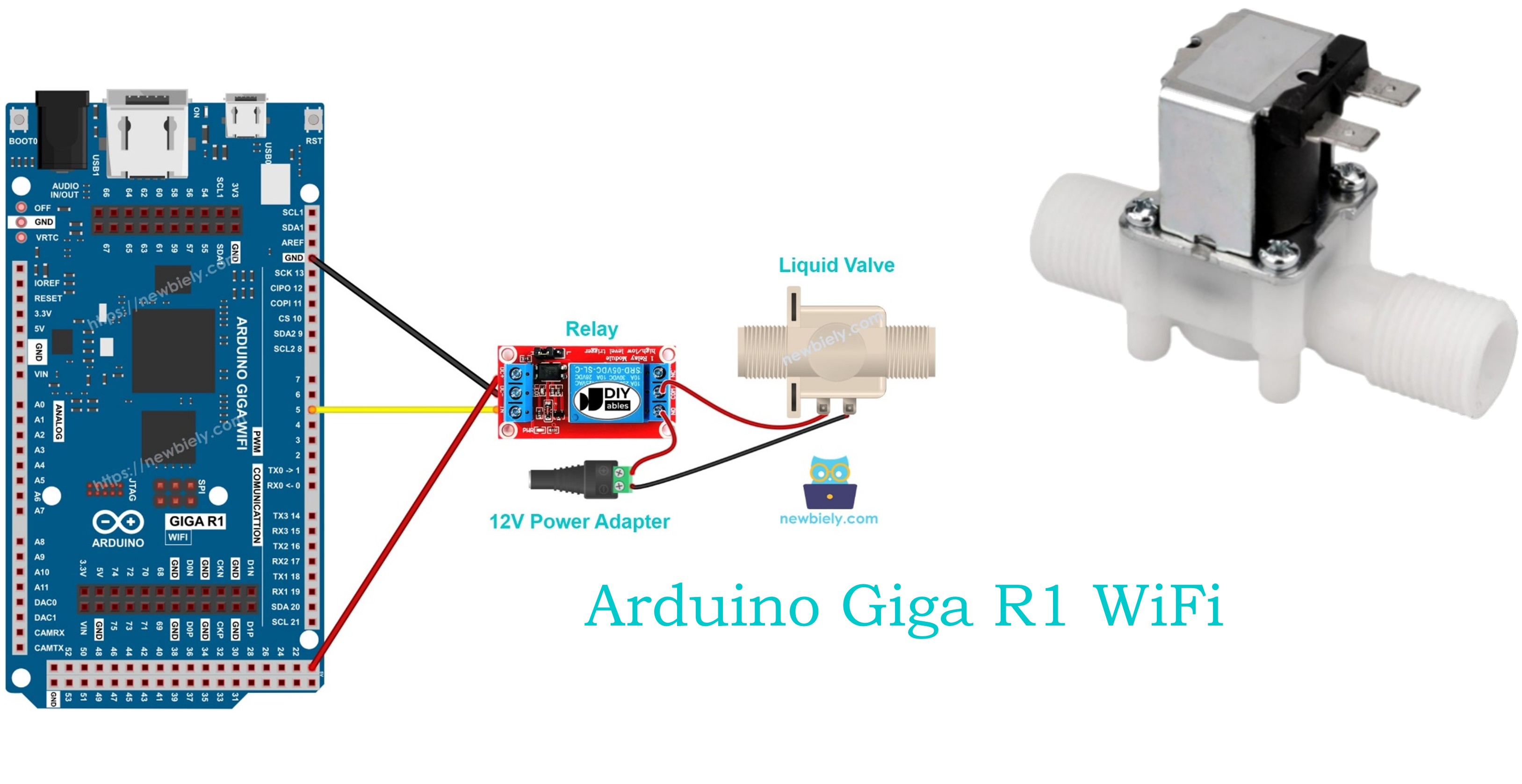
Wiring Diagram
The wiring diagram below demonstrates the complete electrical connection between the Arduino Giga R1 WiFi, relay module, solenoid valve, and power supply. This configuration provides safe, isolated control of high-current valve loads using low-voltage microcontroller signals.
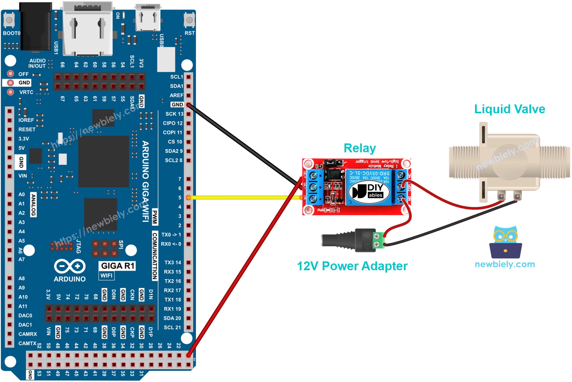
This image is created using Fritzing. Click to enlarge image
Electrical Note: The diagram above shows the minimum viable connection for solenoid valve control. For production or extended use, consider adding LED status indicators for valve state visualization, current monitoring for fault detection, and emergency manual override switches for safety compliance in critical applications.
Power supply requirements include a stable 12V DC source capable of supplying the valve's rated current plus 20% margin for inrush current during switching. Typical solenoid valves exhibit current inrush of 150-200% of steady-state current for the first 50-100 milliseconds after energization. Use appropriately rated power supplies and fusing to handle these transient conditions.
| Component Pin | Arduino Giga R1 WiFi Pin | Notes |
|---|---|---|
| Relay VCC | 5V | Relay module power (3.3V compatible modules available) |
| Relay GND | GND | Common ground reference |
| Relay IN | Digital Pin 7 | Control signal (3.3V logic) |
| Valve Positive | Relay NO Contact | Switched 12V supply |
| Valve Negative | Power Supply GND | Return path for valve current |
| 12V Supply + | Relay Common | Power source for valve |
| 12V Supply - | Arduino GND | Shared ground reference |
Arduino Code
The following implementation demonstrates timer-based valve control with precise on/off cycling. The code is structured to handle relay switching delays and provides clear status reporting through serial communication. Key sections include initialization, timing control, and safety state management to ensure reliable valve operation.
The control algorithm implements a simple state machine with configurable timing intervals for valve open and closed periods. This approach provides predictable valve cycling suitable for irrigation systems, batch processing applications, and automated dispensing equipment. The implementation includes safety features such as startup delay and graceful shutdown handling.
Library requirements are minimal, using only the standard Arduino digital I/O functions for relay control. The code structure separates timing logic from hardware control, making it easily adaptable for different timing requirements or integration with sensor feedback systems.
The below code repeatedly turns the water valve ON for five seconds and OFF for five seconds, creating a continuous cycling pattern suitable for testing and demonstration purposes:
Detailed Instructions
For initial Arduino Giga R1 WiFi setup, refer to the Arduino Giga R1 WiFi Getting Started guide before proceeding with valve control implementation.
- Connect Hardware: Wire the relay module to Arduino Giga R1 WiFi pin 7 (control), 5V (power), and GND (reference). Connect solenoid valve through relay contacts as shown in wiring diagram. Verify all connections match the pinout specifications before applying power.
- Install Libraries: Open Arduino IDE and verify no additional libraries are required — this implementation uses standard digital I/O functions. Confirm IDE is configured for Arduino Giga R1 WiFi board selection under Tools > Board menu.
- Load Code: Copy the valve control code and paste into a new Arduino IDE sketch. Review timing constants and modify the 5-second intervals if different cycling periods are required for your application.
- Upload Program: Connect Arduino to PC via USB cable, select correct COM port under Tools > Port, then click Upload button. Monitor the compilation process for any errors and verify successful upload completion message.
- Verify Operation: Open serial monitor at 9600 baud rate to observe valve state messages. Listen for relay clicking sounds indicating proper switching operation. "Valve ON" and "Valve OFF" messages should appear at 5-second intervals with corresponding relay actuation.
- Test Flow Control: Connect liquid supply to valve inlet and verify flow starts/stops according to serial monitor messages. Check for proper sealing in closed state and unrestricted flow in open state. Monitor for leakage or incomplete valve operation.
- Safety Check: Confirm emergency shutdown capability by pressing Arduino reset button or disconnecting power. Verify valve returns to closed state (normally closed valve) or remains in safe state for your application requirements.
Technical Note: The relay introduces 10-15 milliseconds switching delay between Arduino command and valve actuation. For applications requiring precise timing synchronization, account for this delay in software timing calculations and consider feedback sensors for closed-loop position verification.
Serial Monitor Output
Applications and Project Ideas
Automated Irrigation Controller: Implement soil moisture-based irrigation with multiple solenoid valve zones. The Arduino Giga R1 WiFi's multiple GPIO pins enable control of 8+ valve zones simultaneously, while WiFi connectivity allows remote monitoring and scheduling through web interface or mobile app integration.
Beverage Dispensing System: Control precise liquid portions for automated bartending or beverage vending applications. The dual-core processor enables simultaneous valve timing control and user interface management, while high-speed GPIO ensures accurate dispensing volumes through pulse-width timing control.
Industrial Batch Processing: Automate chemical or food processing with timed ingredient addition sequences. Multiple valve control enables complex recipes with precise timing coordination, while the expanded memory capacity supports storage of numerous processing programs and data logging capabilities.
Hydroponic Nutrient Delivery: Control nutrient solution flow in automated hydroponic systems with pH and conductivity monitoring integration. The Arduino Giga R1 WiFi's analog inputs enable sensor feedback for closed-loop nutrient management, while WiFi connectivity supports remote monitoring and alert notifications.
Laboratory Sample Handling: Implement automated liquid handling for analytical instruments or sample preparation systems. Precise timing control enables accurate volume delivery, while serial communication interfaces support integration with laboratory information management systems (LIMS).
Emergency Shutoff Systems: Deploy as safety interlocks for industrial equipment or chemical processing applications. The reliable relay isolation provides fail-safe operation, while multiple input monitoring enables integration with emergency stop circuits and alarm systems.
Video Tutorial
The accompanying video demonstrates the complete hardware assembly and live code execution. It covers proper relay wiring techniques, power supply connection, and safety considerations for liquid handling systems. The demonstration shows expected valve operation with audible relay switching and visible flow control through transparent tubing.
Challenge Yourself
Challenge: Implement flow rate monitoring by adding a liquid flow sensor to measure actual flow volume. Use interrupts to count flow pulses and calculate gallons per minute, displaying results on serial monitor with valve state correlation.
Challenge: Add WiFi-based remote control using the Arduino Giga R1 WiFi's wireless capabilities. Create a web server interface allowing valve control from smartphones or computers, including scheduling capabilities and usage history logging.
Challenge: Design a multi-zone irrigation controller managing 4-6 solenoid valves with independent timing schedules. Store watering programs in flash memory and implement calendar-based scheduling with seasonal adjustments for different plant zones.
Challenge: Integrate pressure monitoring using an analog pressure sensor to detect valve malfunction or pipe blockages. Implement automatic shutoff when pressure readings indicate abnormal conditions, with diagnostic reporting via serial communication.
Challenge: Build a closed-loop level control system using an ultrasonic distance sensor to maintain liquid level in a tank. Implement PID control algorithm to minimize level oscillation and optimize valve cycling for smooth operation.