Arduino Giga R1 WiFi Sound Sensor
This guide covers sound detection with the Arduino Giga R1 WiFi — from hardware setup to working code. The sound sensor is a versatile acoustic detection device capable of identifying the presence of sound in the surrounding environment through both digital and analog outputs.
The Arduino Giga R1 WiFi's dual-core STM32H747XI processor and generous memory make it an excellent choice for sound-reactive applications that require real-time processing and responsive triggering. This tutorial walks through the complete implementation of both digital and analog sound detection, demonstrating how to leverage the board's GPIO capabilities for precise acoustic sensing.
Sound sensors find widespread application in industrial automation (noise level monitoring), security systems (acoustic intrusion detection), home automation (voice-activated controls), and interactive art installations. The combination of the Arduino Giga R1 WiFi's processing power and the sound sensor's rapid response enables sophisticated sound-reactive projects, such as clap-activated lighting systems, sound-triggered pet feeders, acoustic event loggers, and voice-controlled servo mechanisms.
This documentation covers hardware connections for both digital and analog sound sensor variants, complete code implementations with sensitivity adjustment guidance, troubleshooting techniques for optimal performance, and practical application examples. The tutorial structure progresses from basic detection principles through advanced implementation challenges, providing both immediate functionality and extensibility for complex projects.
Hardware Preparation
Or you can buy the following kits:
| 1 | × | DIYables Sensor Kit (18 sensors/displays) |
Additionally, some of these links are for products from our own brand, DIYables .
Overview of Sound Sensor
The sound sensor is an acoustic detection device designed for environmental sound monitoring and triggering applications. These sensors utilize electret microphone capsules with integrated amplification and signal conditioning circuits to convert acoustic waves into electrical signals suitable for microcontroller interfacing.
Two primary variants are available for different application requirements. Digital sound sensor modules output binary HIGH/LOW signals based on a configurable threshold, operating at 3.3V to 5V logic levels with typical response times under 10ms. Analog sound sensor modules provide both digital threshold outputs and continuous analog voltage outputs (0-5V) proportional to sound intensity, enabling amplitude measurement and complex audio analysis.
The underlying operating principle involves acoustic-to-electrical transduction through a capacitive electret microphone element. Acoustic pressure variations modulate the capacitance between a vibrating diaphragm and a fixed back plate, generating electrical signals that are amplified by an integrated operational amplifier circuit. The digital output stage uses a voltage comparator with hysteresis to provide clean switching behavior and noise immunity.
Typical specifications include frequency response from 20Hz to 20kHz, sensitivity adjustable via onboard potentiometer (typically 48-66dB range), and detection distances up to 25cm for normal conversation levels. Current consumption ranges from 4-6mA during active detection, making them suitable for battery-powered applications.
Integration with the Arduino Giga R1 WiFi leverages the board's 12-bit ADC resolution for precise analog readings and fast GPIO switching for reliable digital detection. The board's dual-core architecture enables real-time sound processing on one core while maintaining communication and control functions on the other, particularly valuable for applications requiring simultaneous WiFi data transmission and acoustic monitoring.
The Digital Sound Sensor Pinout
The pinout defines the electrical interface between the sound sensor and the Arduino Giga R1 WiFi. Correct wiring is essential — an incorrect connection may damage the sensor's amplification circuitry or produce unreliable detection behavior.
- VCC pin: Power input, 3.3V to 5V DC. Connects to Arduino 5V or 3.3V rail to supply the microphone preamp and comparator circuits. Current consumption: 4-6mA typical.
- GND pin: Ground reference, 0V. Connects to Arduino ground plane to complete the power circuit and establish signal reference level.
- OUT pin: Digital output, TTL compatible (0V/3.3V or 0V/5V depending on supply voltage). Active LOW detection — outputs LOW when sound exceeds threshold, HIGH during quiet periods. Connects to any Arduino digital input pin with internal pull-up capability.
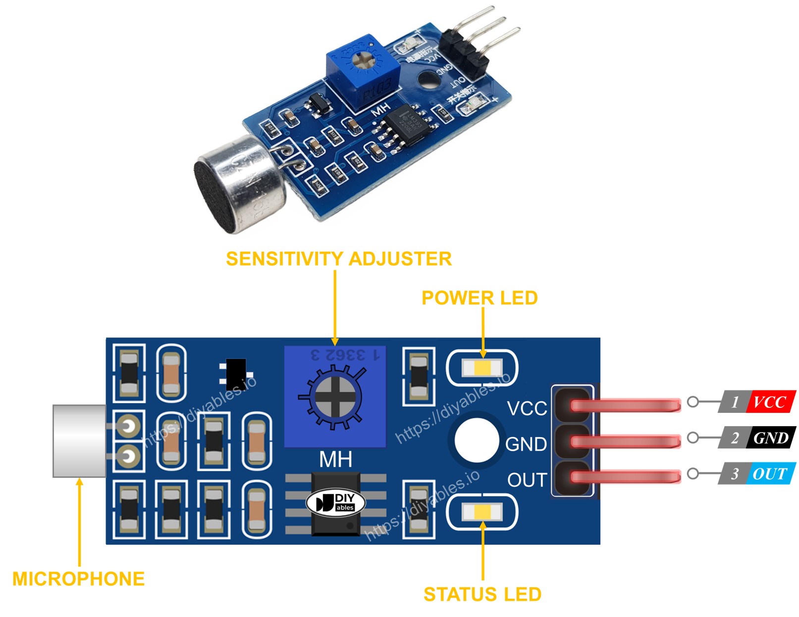
The onboard potentiometer adjusts the comparator threshold voltage, effectively setting the sound level required to trigger the digital output. Clockwise rotation typically increases sensitivity (lower threshold), while counterclockwise rotation decreases sensitivity (higher threshold). The dual LED indicators provide immediate visual feedback: the power LED confirms proper supply voltage, while the detection LED mirrors the digital output state for troubleshooting and sensitivity adjustment.
Electrical Note: For production deployments or extended operation, consider adding a 100μF electrolytic capacitor between VCC and GND near the sensor to reduce power supply noise sensitivity, particularly when operating from switching regulators or shared power rails.
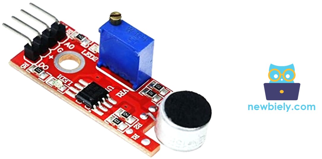
The Analog Sound Sensor Pinout
The analog variant provides enhanced functionality through dual output modes, enabling both threshold detection and continuous amplitude measurement for advanced sound analysis applications.
- + pin: Power input, 5V DC recommended. Connects to Arduino 5V rail to power the microphone amplifier and output buffer stages. Higher supply voltage improves signal-to-noise ratio.
- G pin: Ground reference, 0V. Connects to Arduino ground plane for power return and analog signal reference.
- DO pin: Digital output, TTL compatible (0V/5V). Active LOW detection identical to digital-only sensors. Connects to any Arduino digital input pin for binary sound detection.
- AO pin: Analog output, 0-5V proportional to sound intensity. Connects to Arduino analog input pins (A0-A15) for amplitude measurement. Output impedance: typically 10kΩ.
The analog output provides a DC voltage proportional to the RMS sound level, enabling applications such as sound level meters, noise monitoring systems, and variable-response audio triggers. The potentiometer adjusts only the digital threshold; the analog output remains unaffected, providing full dynamic range regardless of digital sensitivity settings.
GPIO constraints specific to the Arduino Giga R1 WiFi: analog inputs A0-A15 provide 12-bit resolution (0-4095 counts) with 0-3.3V input range. When using 5V analog sensors, ensure proper level shifting or use the board's 5V-tolerant pins where available. The STM32H747XI's fast ADC enables sampling rates up to 1MSPS for real-time audio analysis applications.
How It Works
The sound sensor operates through a three-stage signal processing chain: acoustic transduction, amplification, and threshold comparison. The electret microphone converts sound pressure waves into electrical signals with amplitude proportional to acoustic intensity. An integrated operational amplifier provides approximately 40-60dB gain to bring microphone-level signals up to logic-compatible voltages.
For digital output, a voltage comparator with adjustable threshold determines the switching point. The potentiometer sets the reference voltage for this comparator — higher reference voltages require louder sounds to trigger detection. Hysteresis in the comparator design prevents oscillation around the threshold, ensuring clean digital transitions.
The module implements active-low logic for reliable operation:
- When ambient sound level exceeds the threshold, the digital output pin switches to LOW (0V)
- When ambient sound level falls below the threshold, the digital output pin returns to HIGH (VCC level)
This configuration provides natural pull-up behavior and noise immunity, as electrical interference typically cannot pull outputs low without deliberate switching action.
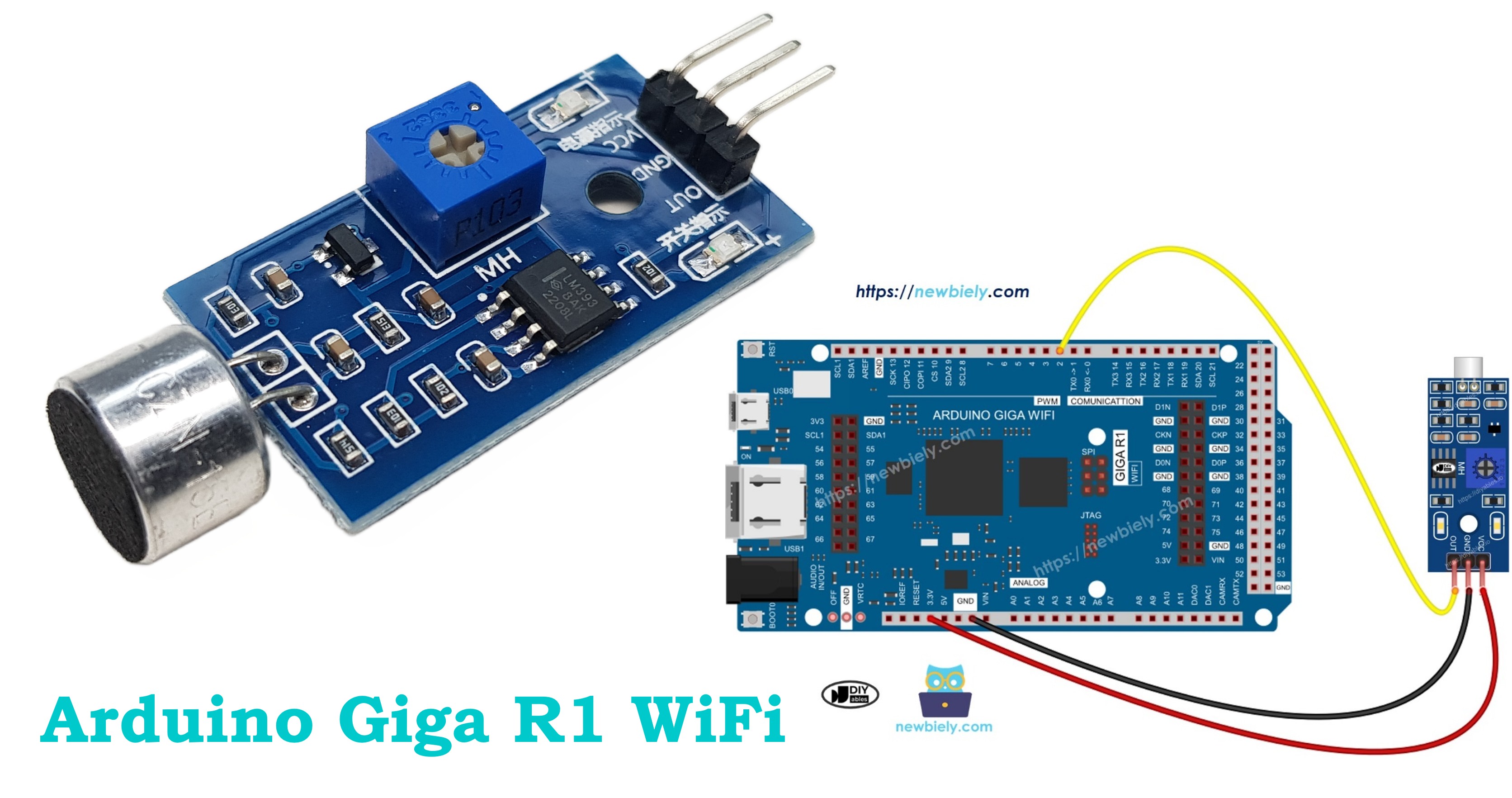
Wiring Diagram
The following implementation demonstrates direct GPIO interfacing between the Arduino Giga R1 WiFi and digital sound sensor. The connection utilizes the board's 5V supply rail and digital input capabilities for reliable sound detection with minimal external components.
Electrical Note: The diagram shows the minimum viable connection for digital sound detection. For production applications or environments with electrical noise, consider adding a 10kΩ pull-up resistor between the OUT pin and VCC, although the Arduino's internal pull-up is typically sufficient for distances under 30cm.
| Sound Sensor Pin | Arduino Giga R1 WiFi Pin |
|---|---|
| VCC | 5V |
| GND | GND |
| OUT | Digital Pin 2 |
The digital pin 2 selection provides interrupt capability (external interrupt 0) for future expansion to event-driven sound detection, reducing CPU overhead compared to continuous polling methods. The Arduino Giga R1 WiFi's robust GPIO drivers can handle the sensor's output current requirements without additional buffering.
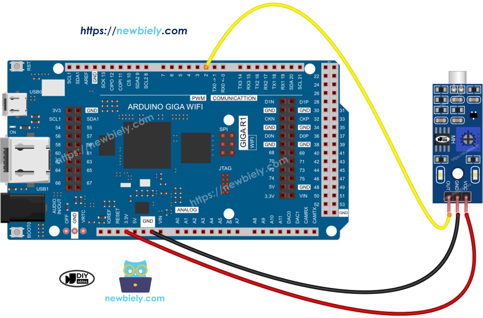
This image is created using Fritzing. Click to enlarge image
How To Program For Sound Sensor
The implementation logic centers on GPIO configuration and digital state polling. The Arduino Giga R1 WiFi's STM32H747XI processor provides fast GPIO access and flexible pin configuration, enabling responsive sound detection with minimal latency.
Initialize the selected Arduino pin as a digital input to enable high-impedance reading of the sensor's output state. The pinMode() function configures the GPIO direction and enables internal pull-up resistors for noise immunity:
Read the instantaneous digital state using digitalRead() to determine current sound detection status. This function returns the logical level present on the specified pin, automatically handling voltage level translation:
The returned value is LOW (0) when sound is detected and HIGH (1) during quiet periods, following the sensor's active-low output logic. For applications requiring edge detection or timing analysis, store previous readings and compare against current values to identify sound onset and cessation events.
Arduino Code - Detecting the sound
Detailed Instructions
Prerequisites: Arduino IDE installed and the Giga R1 WiFi board package configured. Refer to the Getting Started guide for setup instructions.
- Upload Code: Open the provided code in Arduino IDE and click the Upload button. Verify successful compilation and upload completion through the IDE's status messages.
- Connect Hardware: Wire the sound sensor according to the diagram above. Verify VCC connection shows power LED illumination on the sensor module.
- Adjust Sensitivity: Rotate the onboard potentiometer while monitoring the detection LED. Clockwise rotation increases sensitivity (triggers on quieter sounds), counterclockwise decreases sensitivity (requires louder sounds).
- Test Detection: Open Serial Monitor (Tools → Serial Monitor) and set baud rate to 9600. Generate test sounds near the sensor — clapping, speaking, or tapping should trigger detection messages.
- Verify Operation: Confirm detection LED mirrors serial output behavior. Consistent LED activity without sound indicates excessive sensitivity; lack of LED response with loud sounds indicates insufficient sensitivity.
- Fine-tune Response: Adjust potentiometer for desired triggering threshold. Optimal setting produces reliable detection of intended sounds while ignoring background noise and vibrations.
Technical Note: The Arduino Giga R1 WiFi's dual-core architecture enables real-time sound processing extensions. Consider implementing interrupt-driven detection on one core while maintaining WiFi communication or data logging functions on the other core for advanced applications.
Serial Monitor Output
Please keep in mind that if you notice the LED status remaining on constantly or off even when there is sound, you can adjust the potentiometer to fine-tune the sound sensitivity of the sensor.
Now we can customize the code to activate an LED or a light when sound is detected, or even make a servo motor rotate. You can find more information and step-by-step instructions in the tutorials provided at the end of this tutorial.
Application Ideas
Industrial Noise Monitoring: Implement continuous sound level measurement for workplace safety compliance. The Arduino Giga R1 WiFi's WiFi capability enables real-time data transmission to management systems, while the analog sound sensor provides quantitative measurements for OSHA noise exposure calculations.
Smart Home Automation: Create voice-activated lighting and appliance control systems. The board's dual-core architecture allows simultaneous sound detection processing and WiFi communication with home automation networks, enabling responsive voice command recognition and smart speaker integration.
Security and Intrusion Detection: Deploy acoustic monitoring for perimeter security applications. Digital sound sensors provide reliable glass-break detection and unusual noise alerts, while the Arduino Giga R1 WiFi's connectivity enables remote notifications and integration with existing security infrastructure.
Interactive Art Installations: Build sound-reactive displays and kinetic sculptures. The analog sensor output enables proportional responses to sound intensity, while the board's processing power supports complex LED patterns, servo choreography, and multi-channel audio visualization.
Environmental Acoustic Research: Develop wildlife monitoring and urban noise analysis systems. The Arduino Giga R1 WiFi's generous memory supports extended data logging, while WiFi connectivity enables remote data collection and real-time monitoring of acoustic environments.
Machine Condition Monitoring: Monitor industrial equipment through acoustic signature analysis. Changes in motor noise, bearing wear, or mechanical vibrations can be detected and transmitted for predictive maintenance scheduling, reducing downtime and maintenance costs.
Troubleshooting
Enhanced diagnostic procedures for optimal Arduino Giga R1 WiFi sound sensor performance:
- Reduce vibrations: The sound sensor exhibits sensitivity to mechanical vibrations and wind noise due to its high-gain amplification circuitry. Mount the sensor on vibration-dampening materials or isolated platforms. Consider enclosing the sensor in foam windscreens for outdoor applications.
- Consider the sensing range: The effective detection range varies with ambient noise levels and sound frequency content. Typical range is 10-25cm for conversational speech (60-65dB). High-frequency sounds (clapping, metallic impacts) detect at greater distances than low-frequency sounds (voices, motors).
- Check the power supply: Clean, stable power supply is critical for analog circuit performance. Switching regulators and shared power rails can introduce noise that appears as false detections. Add 100μF electrolytic and 0.1μF ceramic capacitors near the sensor VCC pin for improved noise rejection.
- Verify GPIO configuration: Ensure the Arduino pin is configured as INPUT_PULLUP to provide proper bias for the sensor's open-collector output. Floating inputs can cause erratic behavior and false triggering.
- Test with known sound sources: Use consistent test sounds (clapping at fixed distance, smartphone tone generator) to verify repeatable operation and calibrate sensitivity settings objectively.
- Monitor signal integrity: Use the analog output (if available) to observe actual signal levels and confirm the digital threshold is appropriately set relative to ambient noise floor.
Challenge Yourself
Challenge 1: Implement threshold adjustment through software rather than hardware potentiometer. Use the analog output to read sound levels and set digital triggering thresholds programmatically, enabling adaptive sensitivity based on ambient conditions.
Challenge 2: Create a sound-level datalogger using the Arduino Giga R1 WiFi's SD card interface. Log timestamped sound intensity measurements with configurable sampling rates, enabling long-term noise analysis and trend identification.
Challenge 3: Build a multi-zone sound detection system using multiple sensors connected to different GPIO pins. Implement directional sound source identification through time-of-arrival analysis and triangulation algorithms.
Challenge 4: Develop a WiFi-connected sound monitoring network. Transmit real-time sound detection events and analog levels to a central server using the Arduino Giga R1 WiFi's networking capabilities, creating a distributed acoustic monitoring system.
Challenge 5: Implement frequency analysis using the Arduino Giga R1 WiFi's processing power. Sample the analog output at high rates and perform basic FFT analysis to distinguish between different types of sounds (voices, machinery, music) for intelligent triggering applications.