Arduino Giga R1 WiFi Switch
This guide covers ON/OFF switch implementation with the Arduino Giga R1 WiFi. The ON/OFF switch (toggle switch) maintains its state after being pressed, making it ideal for persistent control applications.
This tutorial demonstrates proper debouncing techniques using the ezButton library to ensure reliable state detection. You'll implement a complete switch interface that can detect both the current switch position and state change events.

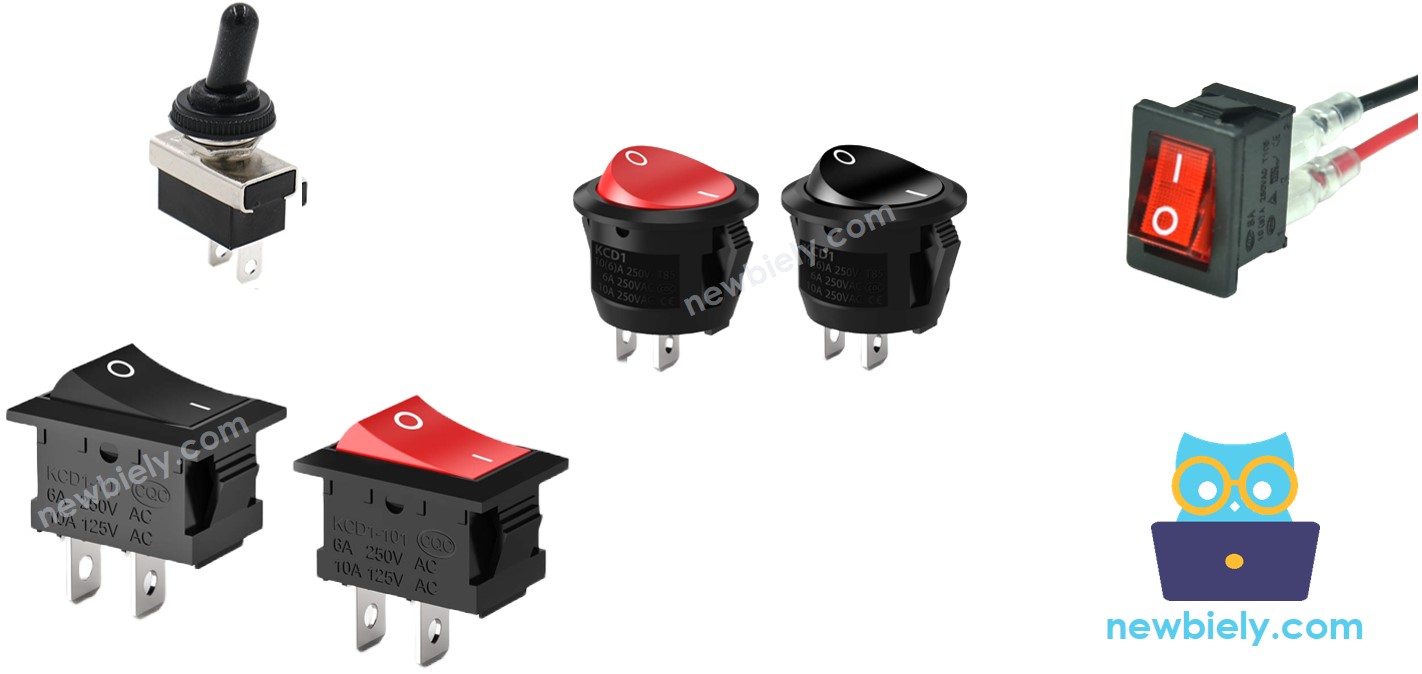
Please do not confuse with the following:
Hardware Preparation
Or you can buy the following kits:
| 1 | × | DIYables Sensor Kit (18 sensors/displays) |
Additionally, some of these links are for products from our own brand, DIYables .
Overview of ON/OFF Switch
An ON/OFF switch is a bistable mechanical device that maintains its selected position (ON or OFF) until manually toggled. Unlike momentary switches that return to default position, ON/OFF switches use a spring-loaded latch that locks contacts in the closed (ON) or open (OFF) position.
Common ratings include 125V AC at 6A or 12V DC at 10A. Operating temperature ranges typically span -20°C to +85°C, with mechanical life exceeding 100,000 cycles.
Pinout
The pinout configuration determines how the switch integrates with the Arduino Giga R1 WiFi's GPIO architecture. Correct terminal identification is essential — an incorrect connection may result in inverted logic or unreliable state detection due to floating inputs.
ON/OFF switches are available in two primary configurations: two-pin and three-pin variants. The two-pin configuration provides simple ON/OFF functionality, while three-pin switches often include a center-off position for tri-state operation.
Two-Pin Switch Configuration: The terminals are electrically equivalent and interchangeable. Terminal 1: Switch contact, connects to either Arduino GPIO or reference voltage. Terminal 2: Switch contact, connects to the complementary connection (Arduino GPIO or reference voltage). No polarity considerations apply to the switch itself, though the circuit configuration determines the logic levels.
For Arduino Giga R1 WiFi integration, one terminal typically connects to a GPIO pin configured with internal pull-up enabled, while the other connects to ground. This configuration provides reliable 3.3V/0V logic levels. The internal pull-up resistors (typically 40kΩ) ensure the GPIO reads HIGH when the switch is open, and LOW when closed to ground.
Three-Pin Switch Configuration (if applicable): Common Terminal: Central connection point. NO (Normally Open): Closed when switch is in ON position. NC (Normally Closed): Open when switch is in ON position. This configuration enables more complex switching logic and can interface with both digital and analog circuits.
Signal integrity considerations include contact bounce duration (typically 1-5ms), which requires software debouncing. The Arduino Giga R1 WiFi's GPIO pins can handle the switch's contact current without external buffering, and the Schmitt trigger inputs provide noise immunity during state transitions.
Wiring Diagram
The wiring implementation establishes the electrical interface between the ON/OFF switch and Arduino Giga R1 WiFi GPIO system. This configuration utilizes the internal pull-up resistor to create a stable high/low logic interface suitable for reliable state detection.
Electrical Note: The diagram below shows the standard pull-up configuration. For production applications or environments with electrical noise, consider adding a 100nF ceramic capacitor between the GPIO pin and ground to provide additional debouncing and noise suppression.
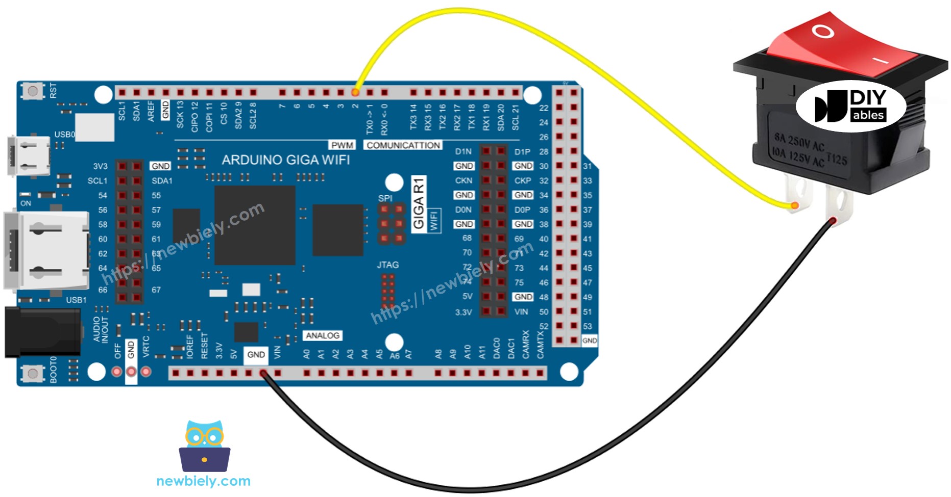
This image is created using Fritzing. Click to enlarge image
The connection leverages the Arduino Giga R1 WiFi's internal pull-up resistors to maintain a defined logic level. When the switch is open (OFF position), the pull-up resistor pulls the GPIO pin to 3.3V (logic HIGH). When the switch closes (ON position), it creates a low-impedance path to ground, pulling the pin to 0V (logic LOW). This configuration prevents floating inputs that could cause erratic readings.
Power Supply Considerations: The switch operates with no external power requirements. Current consumption is minimal—approximately 82.5 microamps when closed (3.3V / 40kΩ pull-up). The Arduino Giga R1 WiFi's GPIO pins can source/sink sufficient current for reliable operation without external buffering.
| Switch Terminal 1 | Arduino Giga R1 WiFi Pin 7 |
|---|---|
| Switch Terminal 2 | GND |
To make the wiring connection stable and firm, we recommend using Soldering Iron to solder wires and ON/OFF switch's pin together, and then use Heat Shrink Tube to make it safe.
How It Works
There are two primary wiring configurations for interfacing ON/OFF switches with the Arduino Giga R1 WiFi. Each configuration provides different logic relationships between the physical switch position and the digital reading:
| Configuration | Terminal 1 | Terminal 2 | Arduino Input State |
|---|---|---|---|
| Pull-up (Recommended) | GND | Arduino Pin 7 (with pull-up) | HIGH = OFF, LOW = ON |
| Pull-down (Alternative) | 3.3V | Arduino Pin 7 (with pull-down) | HIGH = ON, LOW = OFF |
The pull-up configuration is recommended for Arduino Giga R1 WiFi applications because the internal pull-up resistors are readily available and provide excellent noise immunity. The pull-down configuration requires external resistors since the STM32H747XI has stronger internal pull-up capabilities compared to pull-down.
The switching mechanics involve mechanical contact bouncing that creates multiple brief transitions during position changes. The Arduino Giga R1 WiFi's high-speed processor can detect these microsecond-level bounces, requiring software debouncing to ensure clean state transitions for application logic.
Arduino Code - ON/OFF Switch
The implementation demonstrates proper debounced switch reading using the ezButton library, which abstracts the timing complexities and provides clean state detection. The code structure handles both current state polling and state change event detection, making it suitable for applications requiring either continuous monitoring or event-driven responses.
Switch debouncing is essential because mechanical contacts exhibit brief oscillations during state transitions. Without debouncing, the Arduino Giga R1 WiFi's fast processor would detect multiple false triggers during a single physical switch action. The ezButton library implements a time-based debouncing algorithm that filters out these transients while maintaining responsive detection of legitimate state changes.
The library leverages the Arduino Giga R1 WiFi's internal pull-up resistors automatically, eliminating the need for external components. This simplifies the hardware design and reduces component count in space-constrained applications. The debouncing algorithm uses the processor's system timer for precise timing control, typically requiring 50-100 milliseconds for reliable settling.
※ NOTE THAT:
There are two wide-used use cases:
- The first: If the switch's state is ON, do something. If the input state is OFF, do another thing in reverse.
- The second: If the switch's state is changed from ON to OFF (or OFF to ON), do something.
Detailed Instructions
For initial Arduino Giga R1 WiFi setup, refer to the Arduino Giga R1 WiFi Getting Started guide before proceeding.
- Connect Hardware: Wire the ON/OFF switch according to the wiring diagram above. Ensure solid connections between switch terminals and Arduino pins to prevent intermittent operation.
- Prepare Development Environment: Connect the Arduino Giga R1 WiFi to your computer via USB cable. The board should enumerate as a COM port and power indicator should illuminate.
- Configure Arduino IDE: Open Arduino IDE and verify the board manager shows "Arduino Giga R1 WiFi" selected. Confirm the correct COM port is identified for code upload.
- Install ezButton Library: Navigate to Library Manager and install the ezButton library. This library provides debouncing functionality and simplifies switch state management compared to manual debouncing implementations.
- Upload Code: Click the Upload button to compile and transfer the code to the Arduino Giga R1 WiFi. The compilation process should complete without errors, and the upload progress should reach 100%.
- Test Switch Operation: Open the Serial Monitor at 9600 baud. Toggle the switch to ON position and observe the state change detection in the serial output. The debounced readings should show clean transitions without multiple triggers.
- Verify State Persistence: Toggle the switch to OFF position and confirm the state reading remains stable. Multiple readings should show consistent ON or OFF states without fluctuation.
- Monitor Change Events: The serial output displays both continuous state readings and change event notifications. State changes should trigger event messages while maintaining stable readings between transitions.
Technical Note: The ezButton library uses a default debounce time of 50ms, which is suitable for most mechanical switches. For switches with longer settling times or noisy environments, increase the debounce period using switch.setDebounceTime() method to improve reliability.
Application Ideas
Industrial Control Panel: Implement mode selection switching for manufacturing equipment control systems. The Arduino Giga R1 WiFi's dual-core architecture enables real-time monitoring of switch states while executing control algorithms, providing reliable operational mode switching with safety interlocks.
IoT Device Configuration: Create field-configurable IoT nodes where the ON/OFF switch selects between local operation and cloud connectivity modes. The integrated WiFi capability allows remote monitoring of switch positions, enabling technicians to verify configuration states remotely.
Data Logger Power Management: Design battery-powered data acquisition systems where the switch controls logging operation. The Arduino Giga R1 WiFi's low-power modes combined with switch state detection enable efficient power management, extending field deployment duration significantly.
Automated System Override: Implement manual override controls for automated processes where the switch provides immediate operator intervention capability. The persistent state ensures override conditions remain active without continuous operator presence, critical for safety systems.
Multi-Mode Sensor Networks: Deploy sensor nodes with operational mode switching between high-frequency sampling and power-saving modes. The switch state can trigger different sampling rates and communication protocols, optimizing performance for varying application requirements.
Prototype Development Platform: Create configurable hardware platforms where switches select between different operational parameters or feature sets. The Arduino Giga R1 WiFi's generous memory and processing capability support complex configuration matrices controlled by multiple switch inputs.
Video Section
The accompanying video demonstrates the complete hardware assembly process and live code execution. It covers proper soldering techniques for reliable switch connections, library installation procedures, and real-time serial monitor output showing debounced state detection and change events.
Challenge Yourself
Challenge: Implement multiple switch monitoring with individual debouncing and state change callbacks. Create an array of ezButton objects to handle 4-6 switches simultaneously, demonstrating the Arduino Giga R1 WiFi's capability for complex input management.
Challenge: Add EEPROM state persistence to remember switch positions across power cycles. Use the Arduino Giga R1 WiFi's Flash memory to store switch states and restore them during initialization, creating a non-volatile configuration system.
Challenge: Create a WiFi-enabled switch status dashboard that reports all switch positions to a web interface. Leverage the integrated WiFi capability to provide real-time remote monitoring with historical state change logging.
Challenge: Implement interrupt-driven switch detection using the STM32H747XI's external interrupt capabilities. Compare the performance and power consumption between polling-based and interrupt-driven switch monitoring approaches.
Challenge: Design a switch-controlled PWM output system where different switch combinations produce varying output patterns. Use the Arduino Giga R1 WiFi's advanced timer peripherals to generate precise PWM signals based on switch configuration states.