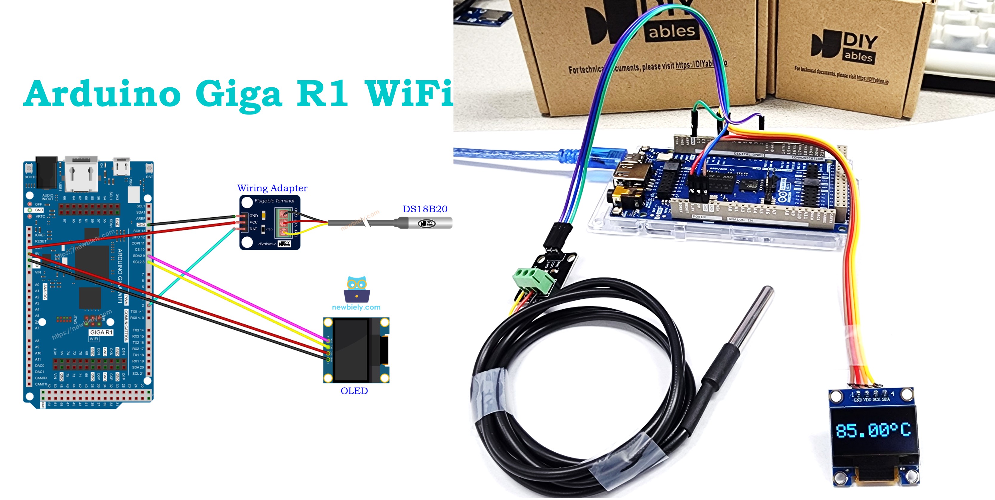
Arduino Giga R1 WiFi Temperature Sensor OLED
This comprehensive guide demonstrates how to integrate the DS18B20 one-wire temperature sensor with an SSD1306 OLED display using the Arduino Giga R1 WiFi — from hardware connections to complete working code. The DS18B20's digital output and precision make it ideal for temperature monitoring applications where accuracy and real-time display are critical.
The Arduino Giga R1 WiFi's dual-core STM32H747XI processor provides ample resources to handle both the OneWire communication protocol for the DS18B20 sensor and I2C communication for the OLED display simultaneously. With 8MB of flash memory and 1MB of RAM, the board can easily manage the required libraries and display operations without performance constraints.
This tutorial walks through the complete implementation process: connecting the DS18B20 temperature sensor to read precise temperature measurements via the OneWire protocol, interfacing with the SSD1306 OLED display through I2C communication, and programming the Arduino Giga R1 WiFi to continuously read temperature data and present it in a clear, centered format on the display. The combination enables real-time temperature monitoring for applications ranging from environmental sensing to process control systems.
The implementation covers library installation, proper wiring configurations, code structure, and practical considerations for reliable operation. By the end of this guide, you'll have a fully functional temperature display system that can serve as a foundation for more complex monitoring and data logging projects.
Hardware Preparation
Or you can buy the following kits:
| 1 | × | DIYables Sensor Kit (18 sensors/displays) |
Additionally, some of these links are for products from our own brand, DIYables .
Buy Note: Many DS18B20 sensors available in the market are unreliable. We strongly recommend buying the sensor from the DIYables brand using the link provided above. We tested it, and it worked reliably.
Overview of OLED and DS18B20 Temperature Sensor
The SSD1306 OLED display is a monochrome graphical display controller designed for compact visual output applications. Operating at 3.3V or 5V with I2C or SPI communication protocols, it provides 128x64 or 128x32 pixel resolution with high contrast and wide viewing angles. The display uses organic light-emitting diodes that require no backlight, resulting in sharp text and graphics with minimal power consumption. The SSD1306 controller includes an integrated charge pump, eliminating the need for external high-voltage generation, and supports multiple addressing modes for flexible pixel manipulation. When interfaced via I2C, the display typically uses address 0x3C or 0x3D, allowing multiple displays on the same bus.
The DS18B20 is a digital temperature sensor designed for precision temperature measurement applications. It operates over a wide temperature range (-55°C to +125°C) with ±0.5°C accuracy from -10°C to +85°C. The sensor uses the Dallas Semiconductor OneWire communication protocol, requiring only a single data line plus power and ground connections. Each DS18B20 contains a unique 64-bit serial code, enabling multiple sensors on the same bus for distributed temperature monitoring. The device performs temperature conversion internally using a 12-bit analog-to-digital converter, providing resolution down to 0.0625°C. Conversion time is typically 750ms for 12-bit resolution, though lower resolutions complete faster.
Both components integrate seamlessly with the Arduino Giga R1 WiFi's GPIO and peripheral capabilities. The OneWire protocol implementation uses bit-banging through any digital pin, while the I2C interface utilizes the board's dedicated SDA and SCL lines. The Arduino's 3.3V logic levels are compatible with both devices, though the DS18B20 can operate with parasitic power from the data line when properly configured with a pull-up resistor.
For reliable OneWire communication, the DS18B20 requires a 4.7kΩ pull-up resistor between the data line and VCC. This resistor ensures proper signal levels during the bus idle state and provides current for parasitic power operation when VCC is not connected. The OLED display requires stable I2C communication with appropriate pull-up resistors, though many modules include these on-board. Power supply considerations include ensuring adequate current capacity for the OLED display, which can consume 20-30mA during full-screen updates.
If you do not know about OLED and DS18B20 Temperature Sensor (pinout, how it works, how to program ...), learn about them in the following tutorials:
Wiring Diagram
The wiring configuration below establishes the essential connections between the Arduino Giga R1 WiFi, DS18B20 temperature sensor, and SSD1306 OLED display. This setup demonstrates a common sensor-display architecture where the microcontroller serves as the central processing unit, polling the temperature sensor and updating the display accordingly.
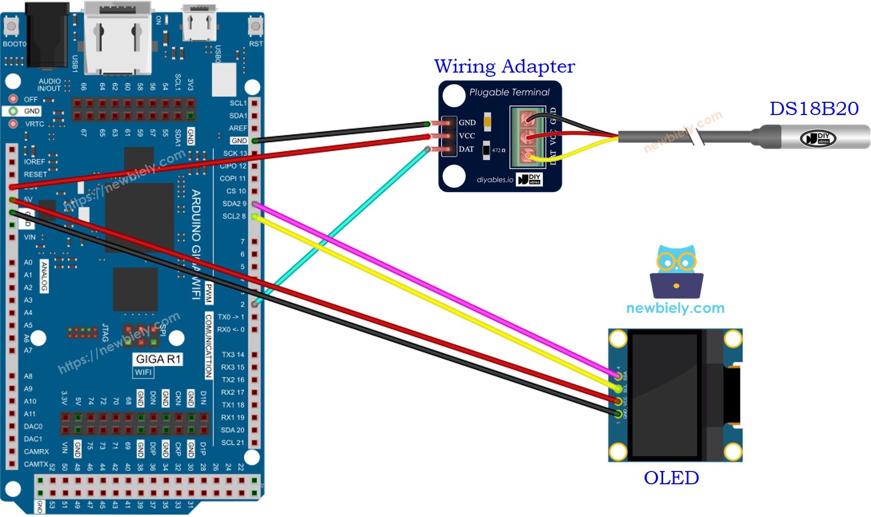
This image is created using Fritzing. Click to enlarge image
Electrical Note: The diagram above shows the minimum viable connection for prototype development. For production or extended use, consider adding decoupling capacitors (0.1µF ceramic) near each device's power pins to reduce noise and improve signal integrity. The DS18B20's pull-up resistor is critical for reliable OneWire communication — ensure the 4.7kΩ resistor is physically close to the sensor connection point.
| DS18B20 Pin | Arduino Giga R1 WiFi Pin | Function |
|---|---|---|
| VCC | 3.3V | Power supply (3.3V recommended) |
| GND | GND | Ground reference |
| DQ | Digital Pin 2 | OneWire data line (requires 4.7kΩ pull-up to VCC) |
| SSD1306 OLED Pin | Arduino Giga R1 WiFi Pin | Function |
|---|---|---|
| VCC | 3.3V | Display power supply |
| GND | GND | Ground reference |
| SDA | SDA2 (Pin 9) | I2C data line |
| SCL | SCL2 (Pin 8) | I2C clock line |
We suggest purchasing a DS18B20 sensor that comes with a wiring adapter for easy connection. The adapter has a built-in resistor, eliminating the need for a separate one in the wiring.
This image is created using Fritzing. Click to enlarge image
The pre-wired DS18B20 modules include the necessary 4.7kΩ pull-up resistor and provide standard 3-pin connector compatibility. These modules simplify prototyping by eliminating discrete component wiring while maintaining the same electrical characteristics as individual components. Current consumption for this configuration typically ranges from 25-35mA during active operation, well within the Arduino Giga R1 WiFi's power supply capabilities.
Arduino Code - Temperature from DS18B20 Temperature Sensor and display it on OLED
The following implementation demonstrates a polling-based sensor reading approach with real-time display updates. The code structure separates initialization, sensor reading, and display functions to maintain clarity and enable future modifications. Key sections handle OneWire device discovery, temperature conversion timing, and OLED text formatting with automatic centering algorithms.
The implementation utilizes the DallasTemperature library to abstract OneWire protocol complexities and the Adafruit SSD1306 library for efficient display management. These libraries provide robust error handling and device management, essential for reliable sensor operation. The code includes temperature conversion timing to ensure accurate readings and display formatting to present temperature data in a user-friendly format.
Detailed Instructions
Prerequisites: Arduino IDE installed and the Giga R1 WiFi board package configured. Refer to the Getting Started guide for setup instructions.
- Install OLED Display Library: Navigate to the Libraries icon in Arduino IDE and search "SSD1306". Select the SSD1306 library by Adafruit and click Install. This library provides comprehensive display control functions including text rendering, graphics primitives, and automatic display buffer management.
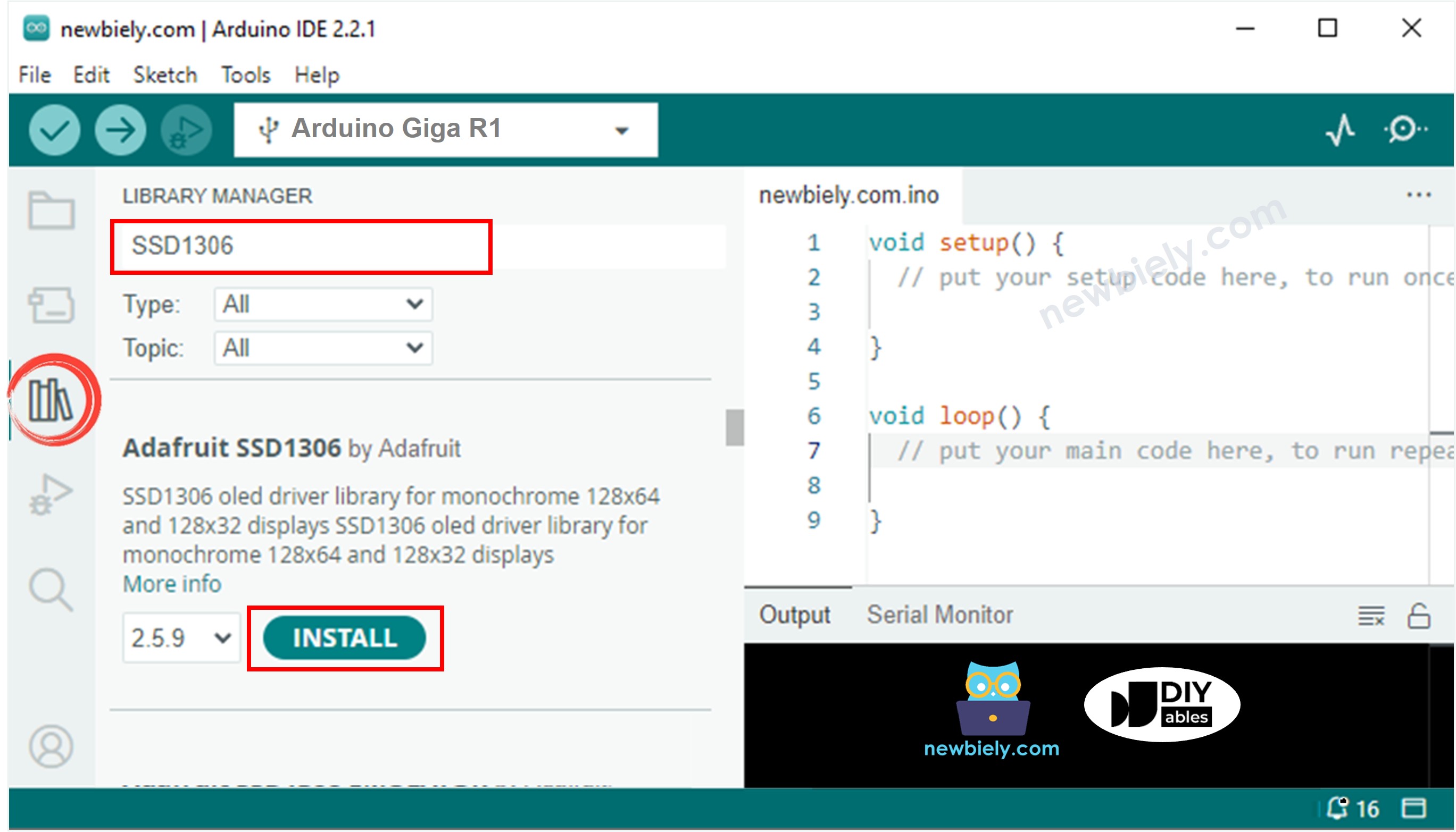
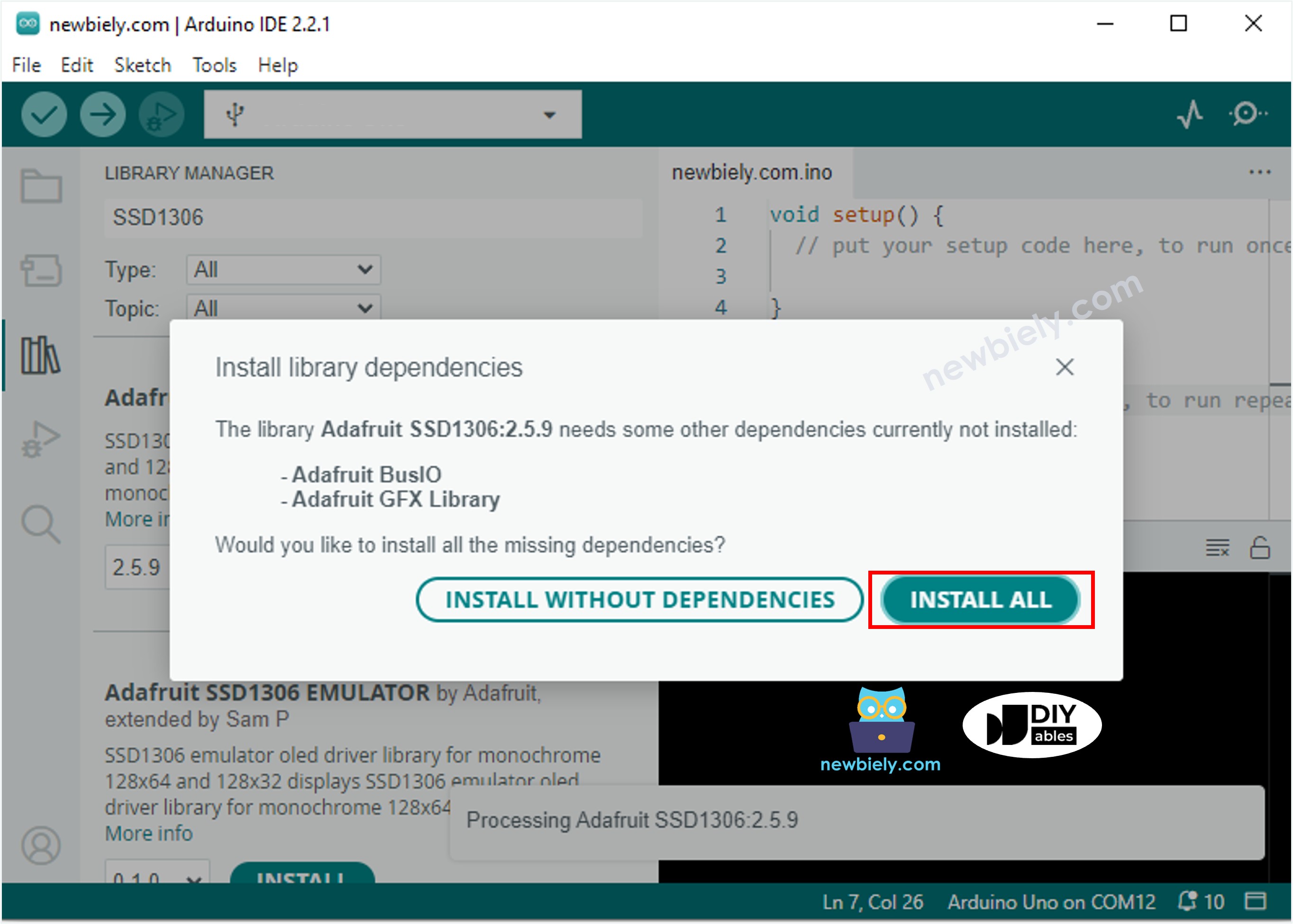
- Install Library Dependencies: Click "Install All" when prompted for additional dependencies. The Adafruit GFX library provides the underlying graphics engine, while Adafruit BusIO handles I2C communication protocols. These dependencies ensure proper display operation across different Arduino platforms.
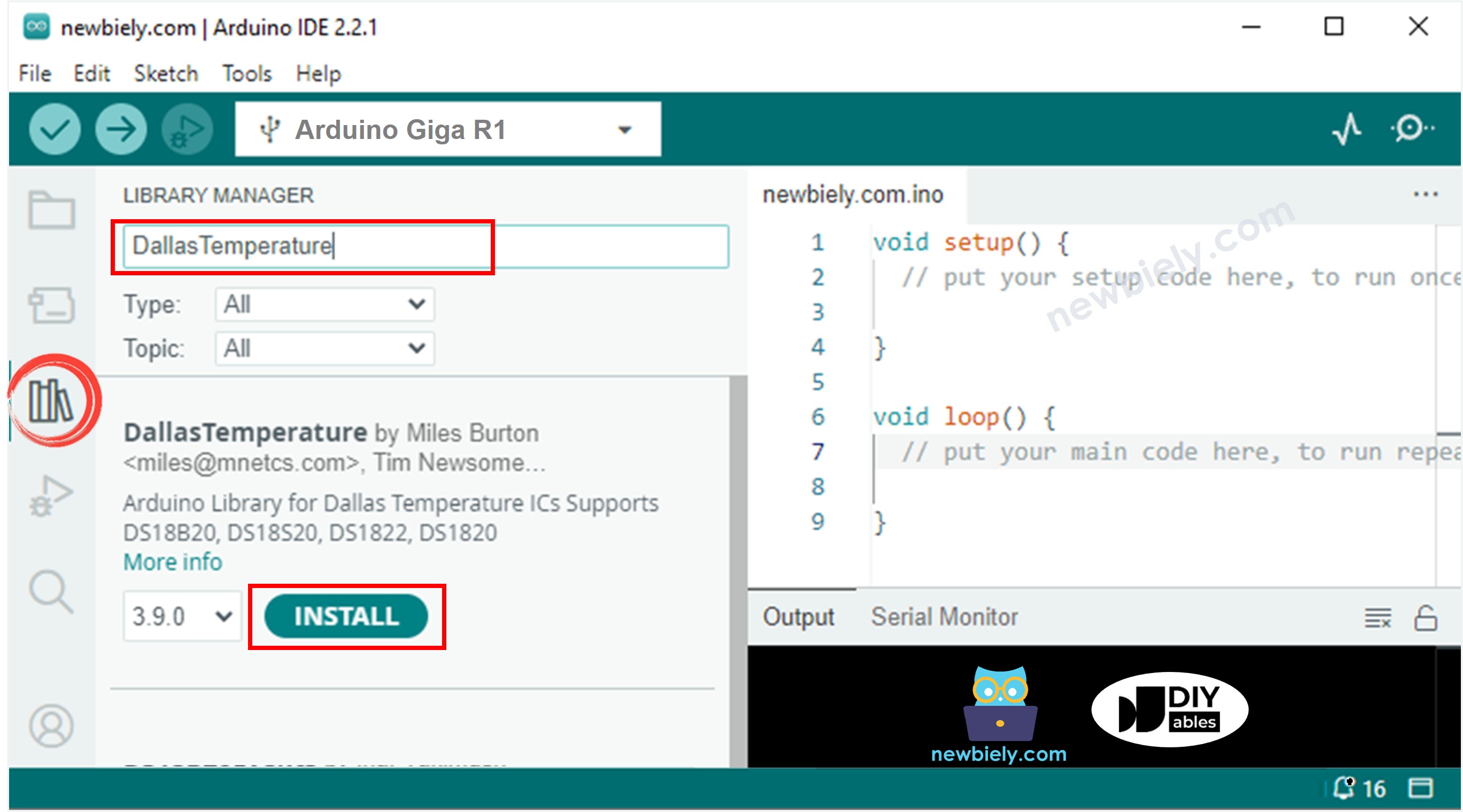
- Install Temperature Sensor Library: Search "DallasTemperature" and install the library by Miles Burton. This library manages OneWire device enumeration, temperature conversion commands, and data parsing for DS18B20 family sensors.
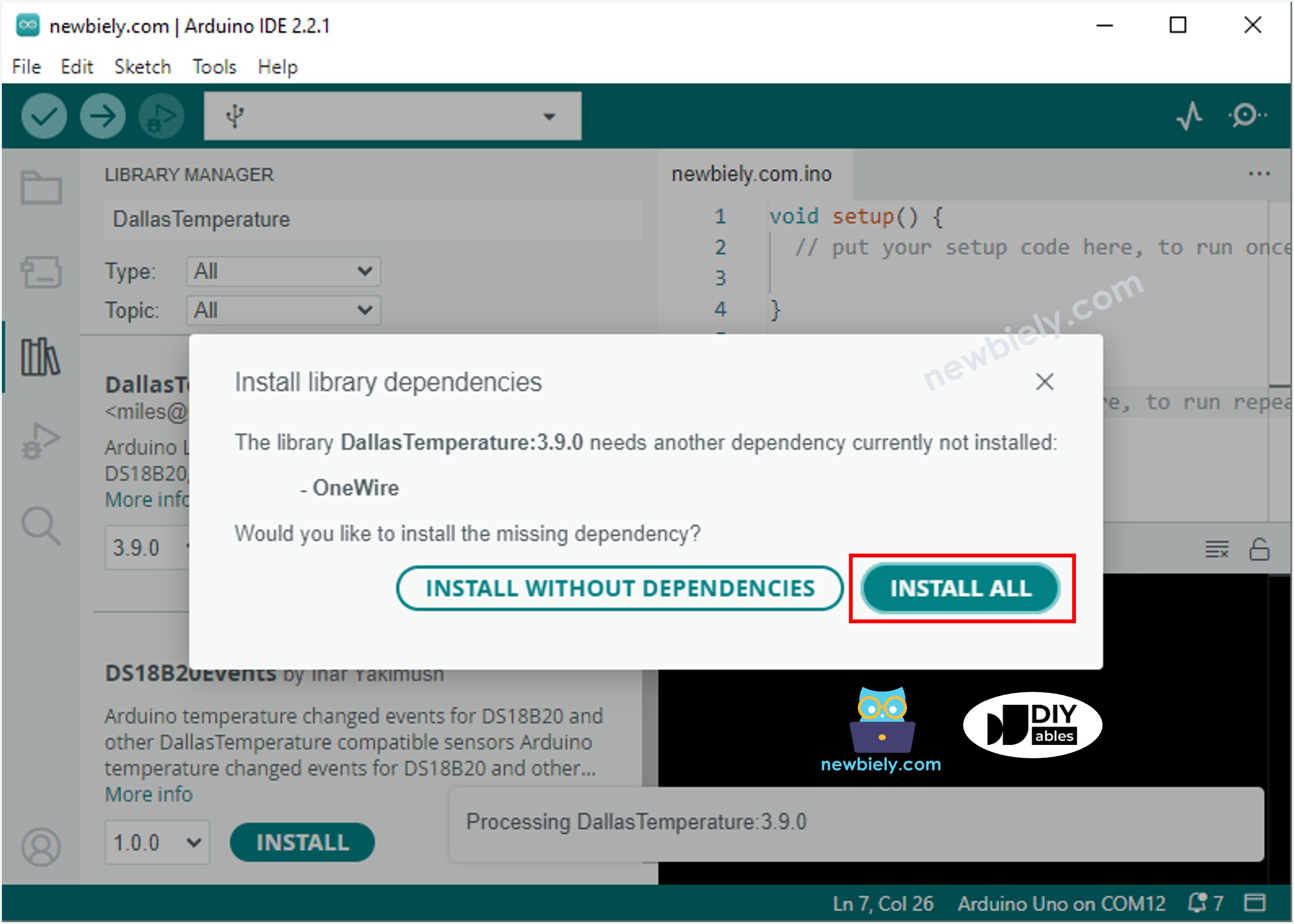
- Install OneWire Dependency: Click "Install All" to add the OneWire library. This fundamental library implements the Dallas Semiconductor OneWire communication protocol, handling the precise timing requirements for reliable sensor communication.
- Verify Wiring Connections: Double-check all connections match the wiring diagram. Incorrect I2C connections will prevent display initialization, while improper DS18B20 wiring results in temperature reading failures or invalid values.
- Upload Code: Copy the provided code to Arduino IDE and upload to the Giga R1 WiFi. Monitor the upload process for compilation errors, which typically indicate missing libraries or syntax issues.
- Test Temperature Response: Place the DS18B20 sensor in environments with different temperatures — room temperature, warm water, or grip the sensor body. The display should update within 1-2 seconds showing temperature changes. Expect accuracy within ±0.5°C for temperatures in the sensor's optimal range.
- Verify Display Operation: Confirm the OLED shows temperature readings centered on screen with proper formatting. If the display remains blank, check I2C connections and verify the display's I2C address matches the code configuration (typically 0x3C).
Technical Note: The temperature conversion process requires approximately 750ms for 12-bit resolution. The code includes appropriate delays to ensure accurate readings. For applications requiring faster response times, consider reducing resolution to 9-bit (94ms conversion time) by modifying the DallasTemperature library configuration.
Serial Monitor Output
Application Ideas
Environmental Monitoring Station: Implement a multi-sensor environmental monitoring system using the Arduino Giga R1 WiFi's dual-core architecture. The primary core handles sensor polling and data processing while the secondary core manages WiFi connectivity and data logging to cloud services. Add humidity, pressure, and air quality sensors for comprehensive environmental data collection.
Industrial Process Control Display: Create a process monitoring interface for industrial applications where temperature control is critical. The Arduino Giga R1 WiFi's robust connectivity enables integration with existing SCADA systems through WiFi or Ethernet protocols. Implement alarm thresholds and visual indicators for temperature deviations.
Laboratory Data Logger: Develop a precision temperature logging system for laboratory environments requiring accurate temperature records. Utilize the Giga R1 WiFi's expanded memory to store temperature data locally with timestamp information, while simultaneously displaying real-time readings on the OLED for immediate observation.
HVAC System Interface: Build an intelligent thermostat interface that displays current temperature and communicates with heating/cooling systems. The Arduino's GPIO capabilities allow control of relay circuits for HVAC equipment, while the OLED provides user feedback and system status information.
Food Safety Monitoring: Implement a food storage temperature monitor for commercial refrigeration applications. The DS18B20's accuracy and the OLED's visibility enable continuous temperature monitoring with immediate visual feedback when temperatures exceed safe storage ranges.
Remote Sensor Network Node: Configure as a wireless sensor node in a distributed temperature monitoring network. The Arduino Giga R1 WiFi's networking capabilities enable multiple sensor locations to report to a central monitoring system while providing local display functionality for on-site personnel.
Video Section
The accompanying video demonstrates the complete hardware assembly process and live code execution. It covers the critical wiring steps for both OneWire and I2C connections, library installation procedures, and real-time temperature display operation. The video shows expected serial monitor output and demonstrates temperature response by testing the sensor in different thermal environments.
Challenge Yourself
Challenge: Implement temperature logging with timestamp data stored to the Arduino's internal flash memory. Create functions to save temperature readings with time stamps and retrieve historical data for display on the OLED when a button is pressed.
Challenge: Add WiFi connectivity to transmit temperature data to a web server or IoT platform like ThingSpeak or Blynk. Utilize the Arduino Giga R1 WiFi's built-in wireless capabilities to create a connected temperature monitoring system with remote access capabilities.
Challenge: Create a multi-sensor system by connecting multiple DS18B20 sensors to the same OneWire bus. Modify the code to display readings from each sensor sequentially on the OLED, cycling through sensors every few seconds. Use the unique sensor addresses to identify and label each reading.
Challenge: Implement a temperature alarm system with visual and audible alerts. Add LED indicators and a buzzer that activate when temperature exceeds programmable thresholds. Store alarm thresholds in EEPROM for persistence across power cycles.
Challenge: Design a data visualization system that graphs temperature trends over time on the OLED display. Create a simple line graph showing the last 10-20 temperature readings, updating the graph as new data arrives. This challenge utilizes the Arduino Giga R1 WiFi's processing power for real-time graphics rendering.
※ NOTE THAT:
The above code automatically horizontal and vertical center aligns the text on OLED display