Arduino Giga R1 WiFi Limit Switch
This guide covers limit switch implementation with the Arduino Giga R1 WiFi — from hardware setup to working code. The limit switch is a fundamental sensing component that detects when moving mechanical parts reach specific positions, making it essential for motor control systems, automated machinery, and safety interlocks.
The Arduino Giga R1 WiFi's robust GPIO capabilities and internal pull-up resistors make it an excellent choice for limit switch integration. You'll implement a complete limit switch interface that can detect both state changes and continuous states, with proper debouncing to ensure reliable operation in industrial and automation applications.
This tutorial walks through the complete implementation, covering electrical specifications, wiring configurations, and Arduino programming with the ezButton library for professional-grade debouncing. You'll learn four different wiring methods to match your specific application requirements, from normally-open to normally-closed configurations.
By the end of this guide, you'll have a working limit switch system that can serve as the foundation for position sensing in CNC machines, 3D printers, conveyor systems, robotic arms, and automated doors. The implementation includes real-time state monitoring and change detection suitable for both prototyping and production applications.
Please do not confuse with the following:
Hardware Preparation
Or you can buy the following kits:
| 1 | × | DIYables Sensor Kit (18 sensors/displays) |
Additionally, some of these links are for products from our own brand, DIYables .
Overview of Limit Switch
A limit switch is an electromechanical switching device designed for position detection and mechanical limit sensing in automated systems. These switches operate through physical contact with moving mechanical components, providing precise position feedback with exceptional reliability and repeatability.
It is called Limit Switch because its main functionality is used to detect the moving object reaching a limit. The underlying mechanism uses a spring-loaded actuator that physically engages with the moving part, causing internal contacts to change state. This mechanical operation provides tactile feedback and eliminates the ambiguity common in proximity sensors, making limit switches the preferred choice for safety-critical applications.
Limit switches typically operate across voltage ranges from 5V to 250V AC/DC with contact ratings from 0.1A to 15A, depending on the model. The KW12-3 and V-156-1C25 models featured in this tutorial are rated for 5A at 250V AC, with contact resistance below 50mΩ and mechanical life exceeding 10 million operations. Operating temperature ranges span -40°C to +85°C for industrial-grade units.
These switches excel in harsh environments where optical or magnetic sensors might fail due to dust, vibration, or electromagnetic interference. The direct mechanical action provides inherent noise immunity and deterministic switching behavior. Common applications include end-of-travel detection in linear actuators, door position sensing in industrial equipment, emergency stop mechanisms, and homing sequences in CNC machinery.
The Arduino Giga R1 WiFi's 5V-tolerant GPIO pins and configurable internal pull-up resistors (typically 20-50kΩ) provide excellent compatibility with standard limit switches. The board's dual-core architecture allows for real-time limit switch monitoring on one core while executing other control tasks on the second core, enabling sophisticated motion control applications.
Pinout
The pinout configuration defines the electrical connections necessary for proper limit switch integration with the Arduino Giga R1 WiFi. Understanding each pin's function and electrical characteristics is critical for reliable operation and preventing component damage through incorrect wiring.
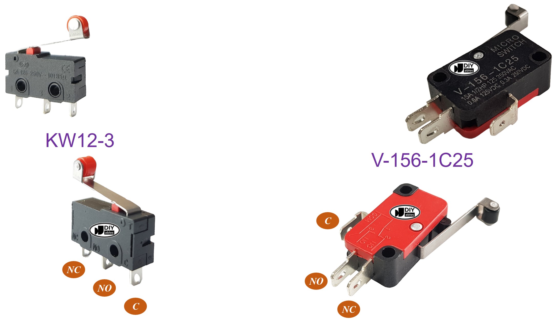
There are various types of limit switches available, but among the most commonly used are the KW12-3 and V-156-1C25. Both of these types have 3 pins:
- C pin (Common): Center contact that provides the switching connection. This pin carries the switched signal and connects internally to either NO or NC depending on actuator position. Maximum current rating: 5A at 125V AC. Connect to power rail (VCC/GND) in your switching configuration.
- NO pin (Normally Open): Contact that closes when the actuator is pressed. In the rest state, this pin has infinite resistance to the C pin. When activated, resistance drops to <50mΩ. Use this configuration when you need the circuit to close upon limit detection.
- NC pin (Normally Closed): Contact that opens when the actuator is pressed. In the rest state, this pin has <50mΩ resistance to the C pin. When activated, resistance becomes infinite. Use this configuration for fail-safe applications where limit detection should break the circuit.
Contact bounce typically lasts 1-5ms during switching transitions, requiring software debouncing for reliable digital sensing. The Arduino Giga R1 WiFi's internal pull-up resistors (enabled via INPUT_PULLUP) eliminate the need for external bias resistors in most configurations.
How It Works
Understanding the switching behavior and electrical states is essential for proper limit switch integration with Arduino systems. The limit switch provides four distinct operating modes based on pin configuration and actuator state.
Although The Limit Switch has 3 pins, a normal application usually uses only two pins: C pin and one of two remaining pins. Accordingly, there are four ways to use limit switch. The below is the wiring table for limit switch and the reading state on Arduino in all four ways:
| C pin | NO pin | NC pin | Arduino Input Pin's State | |
|---|---|---|---|---|
| 1 | GND | Arduino Input Pin (with pull-up) | not connected | HIGH when untouched, LOW when touched |
| 2 | GND | not connected | Arduino Input Pin (with pull-up) | LOW when untouched, HIGH when touched |
| 3 | VCC | Arduino Input Pin (with pull-down) | not connected | LOW when untouched, HIGH when touched |
| 4 | VCC | not connected | Arduino Input Pin (with pull-down) | HIGH when untouched, LOW when touched |
Configuration 1 (Active-Low with Pull-Up) is the most commonly used setup as it provides noise immunity and compatibility with the Arduino Giga R1 WiFi's internal pull-up resistors. When the limit is not reached, the pull-up resistor maintains the input at logic HIGH (3.3V). When the actuator is pressed, the C pin connects to NO pin, pulling the input to GND (logic LOW).
Configuration 2 (Active-High with Pull-Up) uses the normally-closed contact, creating an inverted logic where limit detection produces a HIGH signal. This configuration is preferred for safety interlocks where a broken wire should trigger a fault condition.
For each way, we can swap GND pin and Arduino Input Pin. Therefore, we have 8 way to connect Arduino to a limit switch.
The switching action includes a brief contact bounce period where the contacts rapidly make and break connection before settling to the final state. This mechanical bounce creates multiple logic transitions that must be filtered through software debouncing to prevent false triggering in Arduino applications.
We only need to choose one of the above four ways. The rest of tutorial will use the first way.
Wiring Diagram
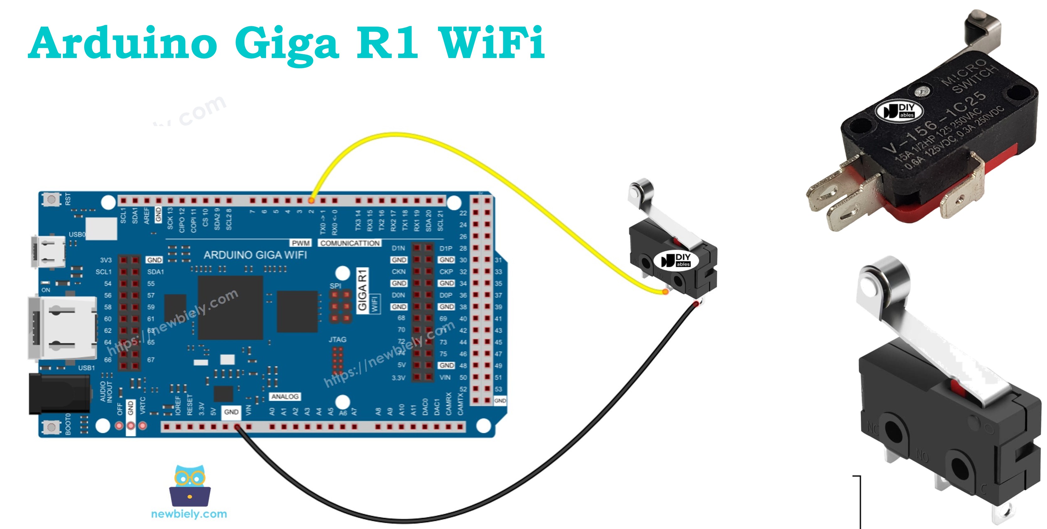
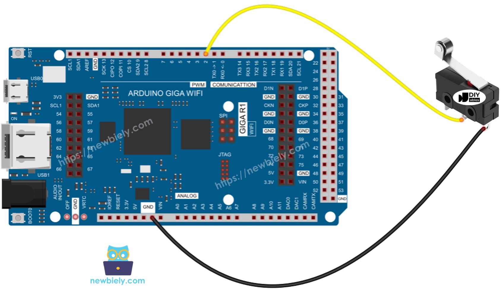
The wiring implementation demonstrates Configuration 1 (Active-Low with Pull-Up) for optimal compatibility with the Arduino Giga R1 WiFi's GPIO architecture. This configuration provides excellent noise immunity and eliminates the need for external bias components.
Electrical Note: The diagram above shows the minimum viable connection for prototyping. For production or extended use, consider adding a 100nF ceramic capacitor between the Arduino input pin and GND to suppress electromagnetic interference, and use shielded cable for runs longer than 30cm.
| Component Pin | Arduino Giga R1 WiFi Pin |
|---|---|
| C (Common) | GND |
| NO (Normally Open) | Digital Pin 7 (with internal pull-up enabled) |
| NC (Normally Closed) | Not Connected |
The Arduino Giga R1 WiFi's internal pull-up resistor (approximately 20-50kΩ) maintains the input pin at logic HIGH (3.3V) when the limit switch is not actuated. When the moving mechanism presses the actuator, the NO contact closes, connecting the input pin directly to GND through the C pin, creating a reliable logic LOW state.
Power consumption in this configuration is minimal: approximately 66-165μA when activated (3.3V ÷ 20-50kΩ), well within the Arduino Giga R1 WiFi's GPIO current sourcing capability. The low current also extends contact life by minimizing arcing during switching transitions.
This image is created using Fritzing. Click to enlarge image
To make the wiring connection stable and firm, we recommend using Soldering Iron to solder wires and limit switch's pin together, and then use Heat Shrink Tube to make it safe.
Arduino Code - Limit Switch
The following implementation demonstrates professional-grade limit switch handling using the ezButton library for hardware debouncing and state management. The code is structured to handle both continuous state monitoring and edge detection, providing a robust foundation for motion control and automation applications.
Just like a button, a limit switch also needs to be debounced (See more at Why needs debounce for the button/limit switch?). Debouncing make the code complicated. Fortunately, the ezButton library supports the debouncing functionm, The library also uses internal pull-up register. These make easy to us to program
The ezButton library provides hardware-level debouncing with configurable timing (default 50ms), eliminating the mechanical contact bounce that occurs during switching transitions. This library abstracts the complexity of state management while providing both level detection (isPressed/isReleased) and edge detection (wasPressed/wasReleased) capabilities essential for automation applications.
Key implementation features include automatic internal pull-up configuration, non-blocking operation compatible with real-time systems, and memory-efficient state tracking. The library handles the contact bounce filtering internally, ensuring that each physical switch action registers as exactly one logical event regardless of mechanical characteristics.
※ NOTE THAT:
There are two wide-used use cases:
- The first: If the switch's state is TOUCHED, do something. If the input state is UNTOUCHED, do another thing in reverse.
- The second: If the switch's state is changed from UNTOUCHED to TOUCHED (or TOUCHED to UNTOUCHED), do something.
Detailed Instructions
For initial Arduino Giga R1 WiFi setup, refer to the Arduino Giga R1 WiFi Getting Started guide before proceeding.
- Wire the connections: Connect the limit switch C pin to GND and NO pin to digital pin 7 on the Arduino Giga R1 WiFi. Ensure secure connections to prevent intermittent contact issues.
- Connect Arduino to PC: Use the USB 2.0 cable to establish communication. The Arduino IDE should recognize the Giga R1 WiFi automatically once drivers are installed.
- Install ezButton library: Navigate to Tools > Manage Libraries, search for "ezButton", and install the latest version. This library provides professional debouncing and eliminates the need for external pull-up resistors.
- Configure board settings: Select "Arduino Giga R1 WiFi" from the board menu and choose the appropriate port. Verify the connection by checking that the board appears in the port list.
- Upload the code: Click the Upload button to compile and transfer the program. The process typically takes 10-15 seconds due to the Giga R1 WiFi's generous program memory.
- Test limit switch operation: Physically actuate the limit switch several times while monitoring the serial output. You should observe clean state transitions without spurious readings due to contact bounce.
- Verify serial monitor output: Open the Serial Monitor at 9600 baud. The display should show "UNTOUCHED" when the actuator is released and "TOUCHED" when pressed, with clear transition messages during state changes.
Technical Note: The ezButton library implements a 50ms default debounce period, which is suitable for most mechanical limit switches. For applications requiring faster response times, this can be adjusted using the setDebounceTime() function, though values below 10ms may allow contact bounce to cause false triggers.
Serial Monitor Output
Application Ideas
Industrial End-Stop Detection: Implement precise position limiting in CNC machines, 3D printers, and linear actuators. The Arduino Giga R1 WiFi's dual-core architecture enables real-time limit monitoring on one core while executing motion control algorithms on the second core, preventing mechanical damage from over-travel conditions.
Automated Door Position Sensing: Monitor door and gate positions in access control systems, ensuring proper closure before engaging security locks. The limit switch provides definitive mechanical confirmation that proximity sensors cannot match, while the Giga R1 WiFi's WiFi capability enables remote status monitoring and integration with building automation systems.
Conveyor Belt Safety Interlocks: Create emergency stop mechanisms that halt conveyor operation when guards are opened or personnel enter restricted areas. Multiple limit switches can be monitored simultaneously using the Arduino Giga R1 WiFi's abundant GPIO pins, with state changes triggering immediate safety shutdowns through interrupt-driven responses.
Robotic Arm Homing Sequences: Establish reference positions for servo and stepper motor-driven robotic systems. The Arduino Giga R1 WiFi's precise timing capabilities ensure accurate positioning while the mechanical reliability of limit switches provides consistent homing accuracy across millions of cycles.
Elevator Floor Detection: Implement floor-level sensing in elevator control systems, providing backup position confirmation to encoder-based systems. The robust mechanical operation ensures reliable operation in shaft environments where optical sensors might fail due to dust or debris accumulation.
Automated Material Handling: Control pneumatic cylinders and linear actuators in manufacturing equipment, detecting full extension and retraction positions. Integration with the Arduino Giga R1 WiFi's communication capabilities enables real-time production monitoring and predictive maintenance based on cycle counting.
Video Section
The accompanying video demonstrates the complete hardware assembly process and live code execution with the Arduino Giga R1 WiFi limit switch system. It covers the critical wiring connections, proper switch mounting techniques, and real-time serial monitor output showing both state changes and continuous monitoring. The demonstration includes multiple activation cycles to illustrate the debouncing effectiveness and response timing characteristics.
Challenge Yourself
Challenge: Implement a dual-limit travel control system that monitors both minimum and maximum positions of a linear actuator. Connect two limit switches to separate GPIO pins and create logic that prevents motor operation beyond either limit while allowing bidirectional movement within the safe zone.
Challenge: Add data logging functionality that records limit switch activation timestamps to an SD card for maintenance analysis. Use the Arduino Giga R1 WiFi's SPI interface to interface with an SD card module, creating CSV files that track activation frequency and timing patterns for predictive maintenance applications.
Challenge: Create a WiFi-enabled limit switch monitoring system that publishes switch states to a web dashboard in real-time. Leverage the Arduino Giga R1 WiFi's built-in WiFi capability to implement a REST API that external systems can query for current switch status and historical activation data.
Challenge: Design a safety interlock system using multiple limit switches that implements two-hand operation control. Require simultaneous activation of two switches within a specific time window to enable dangerous machinery operation, automatically disabling the system if switches are held down (preventing bypass attempts).
Challenge: Implement interrupt-driven limit switch monitoring that can wake the Arduino Giga R1 WiFi from deep sleep mode for battery-powered applications. Configure external interrupts on switch state changes while maintaining ultra-low power consumption during inactive periods, suitable for remote monitoring installations.