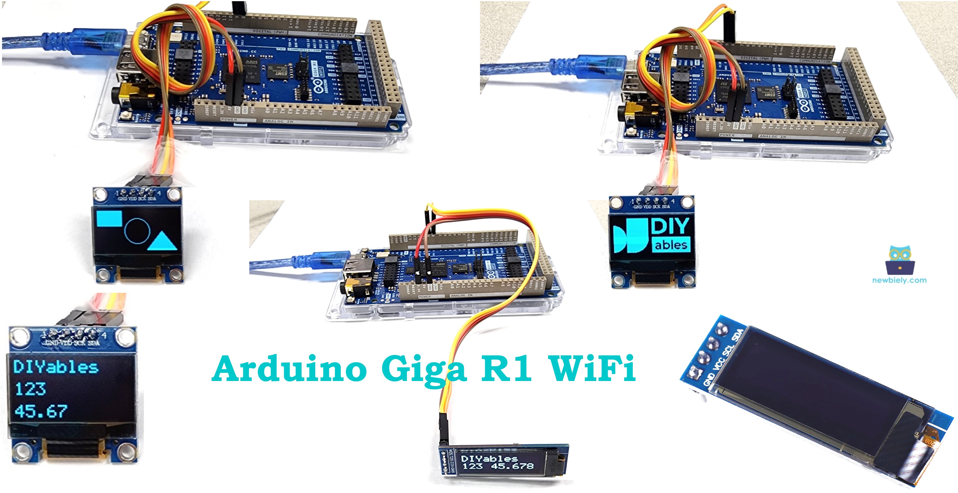
Arduino Giga R1 WiFi OLED Display
This tutorial demonstrates how to use OLED displays with the Arduino Giga R1 WiFi for high-contrast visual output. By the end, you will have working implementations for text display, graphics rendering, and image presentation on both 128x64 and 128x32 OLED modules.
- Wiring SSD1306 OLED displays to the Arduino Giga R1 WiFi
- Installing and configuring the SSD1306 library
- Writing and uploading code for text, graphics, and images
- Viewing real-time display output and serial monitor feedback
Hardware Preparation
Or you can buy the following kits:
| 1 | × | DIYables Sensor Kit (18 sensors/displays) |
Additionally, some of these links are for products from our own brand, DIYables .
Overview of OLED Display
OLED (Organic Light-Emitting Diode) displays are self-illuminating display devices designed for high-contrast visual output without requiring backlighting. Unlike traditional LCD displays, each pixel in an OLED generates its own light through electroluminescence, resulting in true blacks, superior contrast ratios (typically 1,000,000:1), and reduced power consumption when displaying dark content. The organic compounds emit light when an electric current is applied, creating vivid colors and sharp text rendering.
The underlying operating principle involves organic semiconductor layers sandwiched between two electrodes. When voltage is applied, electrons and holes recombine in the emission layer, releasing photons at specific wavelengths determined by the organic material composition. This direct light generation eliminates the need for backlighting systems, allowing for ultra-thin form factors—often less than 3mm thick including the driver board.
OLED displays are categorized by several key specifications:
Communication Interfaces:
- I2C (Inter-Integrated Circuit): 3.4 MHz maximum clock speed, requires only 2 data lines (SDA/SCL), supports multiple device addressing
- SPI (Serial Peripheral Interface): Up to 10 MHz clock speed, requires 4-6 pins but offers faster refresh rates
Resolution and Physical Dimensions:
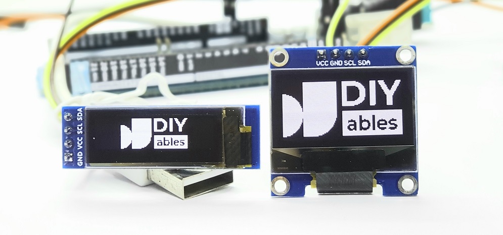
- 128x64 pixels: 0.96" diagonal, active area 21.74 x 10.86mm, pixel pitch 0.17mm
- 128x32 pixels: 0.91" diagonal, active area 22.38 x 5.58mm, pixel pitch 0.175mm
Electrical Characteristics:
- Supply voltage: 3.3V to 5V (internal voltage regulation)
- Operating current: 20mA typical (full white), 8mA (normal mixed content)
- Operating temperature: -40°C to +85°C
- Viewing angle: >160° (nearly omnidirectional)
Compared to LCD alternatives, OLED displays offer faster response times (typically <10μs vs 15-25ms for LCD), wider viewing angles, and better performance in extreme temperatures. However, they have limited lifespan under high brightness conditions and can suffer from burn-in with static content over extended periods.
For Arduino Giga R1 WiFi integration, the dual M7+M4 core architecture provides sufficient processing power for smooth graphics rendering and display updates. The board's expanded 8MB PSRAM enables storage of multiple bitmap images and complex graphical elements without memory constraints typical of smaller Arduino boards.
This tutorial focuses on SSD1306 I2C OLED displays in both 128x64 and 128x32 configurations, which represent the most common OLED modules for embedded applications due to their balance of resolution, power efficiency, and cost-effectiveness.
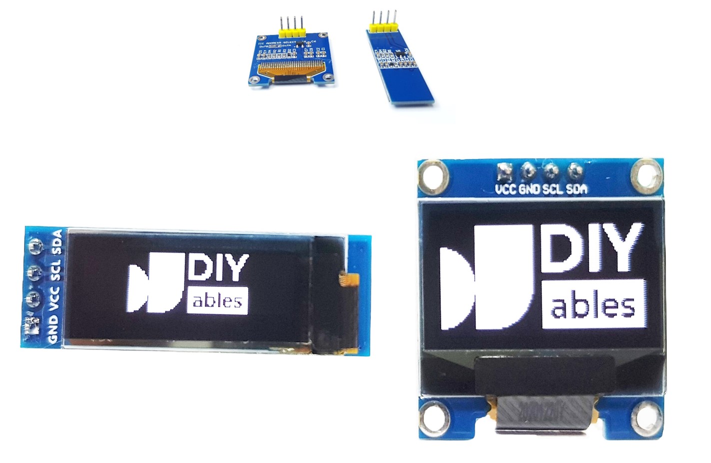
I2C OLED Display Pinout
The pinout configuration maps each physical connection to its electrical function within the I2C communication protocol. Correct wiring is critical—incorrect connections may damage the display module or produce unreliable communication that manifests as blank screens or garbled output.
Pin Specifications:
- GND: Ground reference, 0V. Connects to Arduino ground to establish common voltage reference for reliable digital communication.
- VCC: Power supply input, 3.3V to 5.5V tolerance. Connects to Arduino 5V or 3.3V rail. Internal voltage regulators step down to 3.3V for logic and generate high voltages (up to 15V) for OLED driving.
- SCL (Serial Clock Line): I2C clock input, 5V tolerant with internal pull-up resistors (typically 10kΩ). Connects to Arduino I2C clock pin. Maximum frequency 400 kHz (Fast Mode) for SSD1306 controller.
- SDA (Serial Data Line): I2C bidirectional data line, 5V tolerant with internal pull-up resistors. Connects to Arduino I2C data pin for command and display data transmission.
The SSD1306 controller includes internal pull-up resistors on I2C lines, eliminating the need for external pull-up components in most applications. Signal logic levels follow I2C specification: logic high >3.0V, logic low <0.8V at VCC=5V operation.
Arduino Giga R1 WiFi I2C Considerations:
The Arduino Giga R1 WiFi implements I2C through the STM32H747XI's I2C peripheral, supporting both Standard Mode (100 kHz) and Fast Mode (400 kHz) operation. The Wire2 I2C pins (SDA2=9, SCL2=8) feature hardware I2C controller with clock stretching support and automatic error recovery.
Common wiring errors include reversed SDA/SCL connections (causing communication failure with no acknowledgment), incorrect power supply voltage (leading to erratic behavior), and missing ground connections (resulting in floating logic levels and intermittent operation).
※ NOTE THAT:
- The order of the OLED module's pins can vary between manufacturers and module types. ALWAYS use the labels printed on the OLED module. Look closely!
- This tutorial uses the OLED display that uses the SSD1306 I2C driver. We have tested with the OLED display from DIYables. It works without any issues.
Wiring Diagram
The wiring implementation connects the SSD1306 OLED display to the Arduino Giga R1 WiFi's dedicated I2C interface pins. This configuration utilizes the hardware I2C controller for optimal performance and reliability compared to bit-banged software I2C alternatives.
Electrical Note: The diagram shows the minimum viable connection for development and prototyping. For production applications or extended operating periods, consider adding 100μF decoupling capacitors near the OLED power pins and ferrite beads on I2C lines to suppress electromagnetic interference, especially when using long connection wires (>15cm).
The Arduino Giga R1 WiFi supplies sufficient current through its regulated 5V rail to power OLED displays. Typical current consumption ranges from 8-20mA depending on displayed content brightness and complexity.
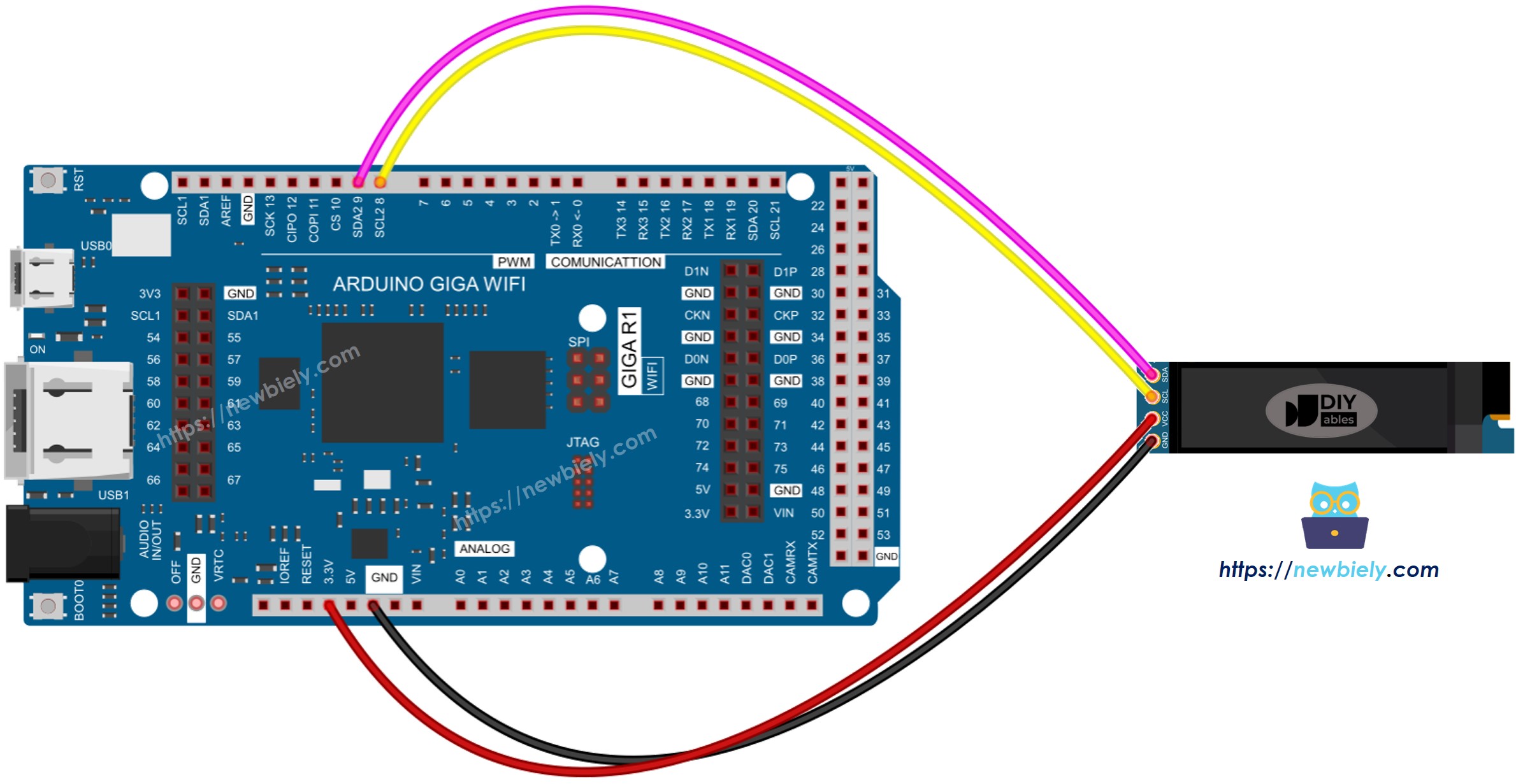
- Wiring diagram between Arduino and OLED 128x64
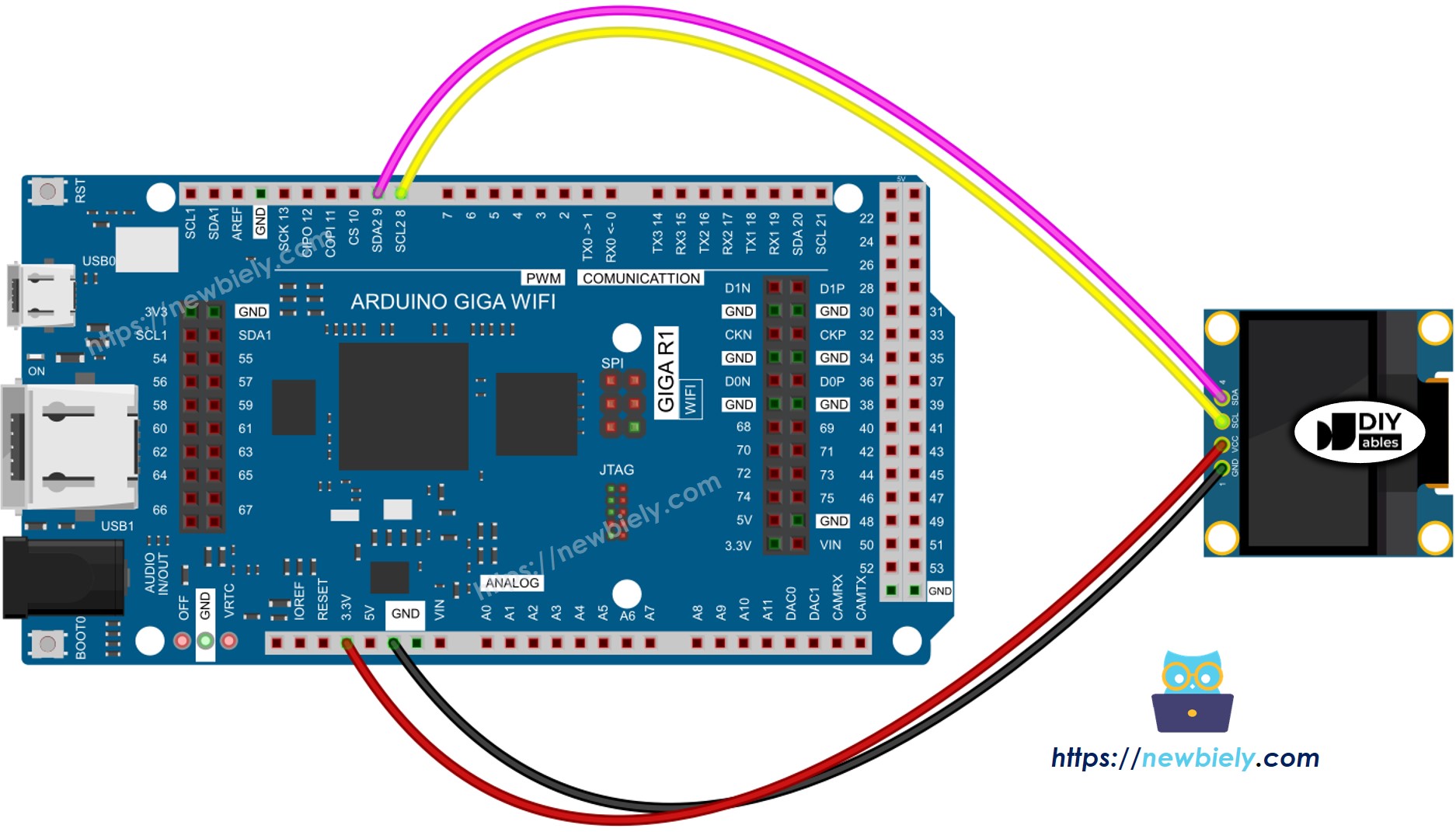
This image is created using Fritzing. Click to enlarge image
- Wiring diagram between Arduino and OLED 128x32
This image is created using Fritzing. Click to enlarge image
- The real wiring diagram between Arduino and OLED 128x64
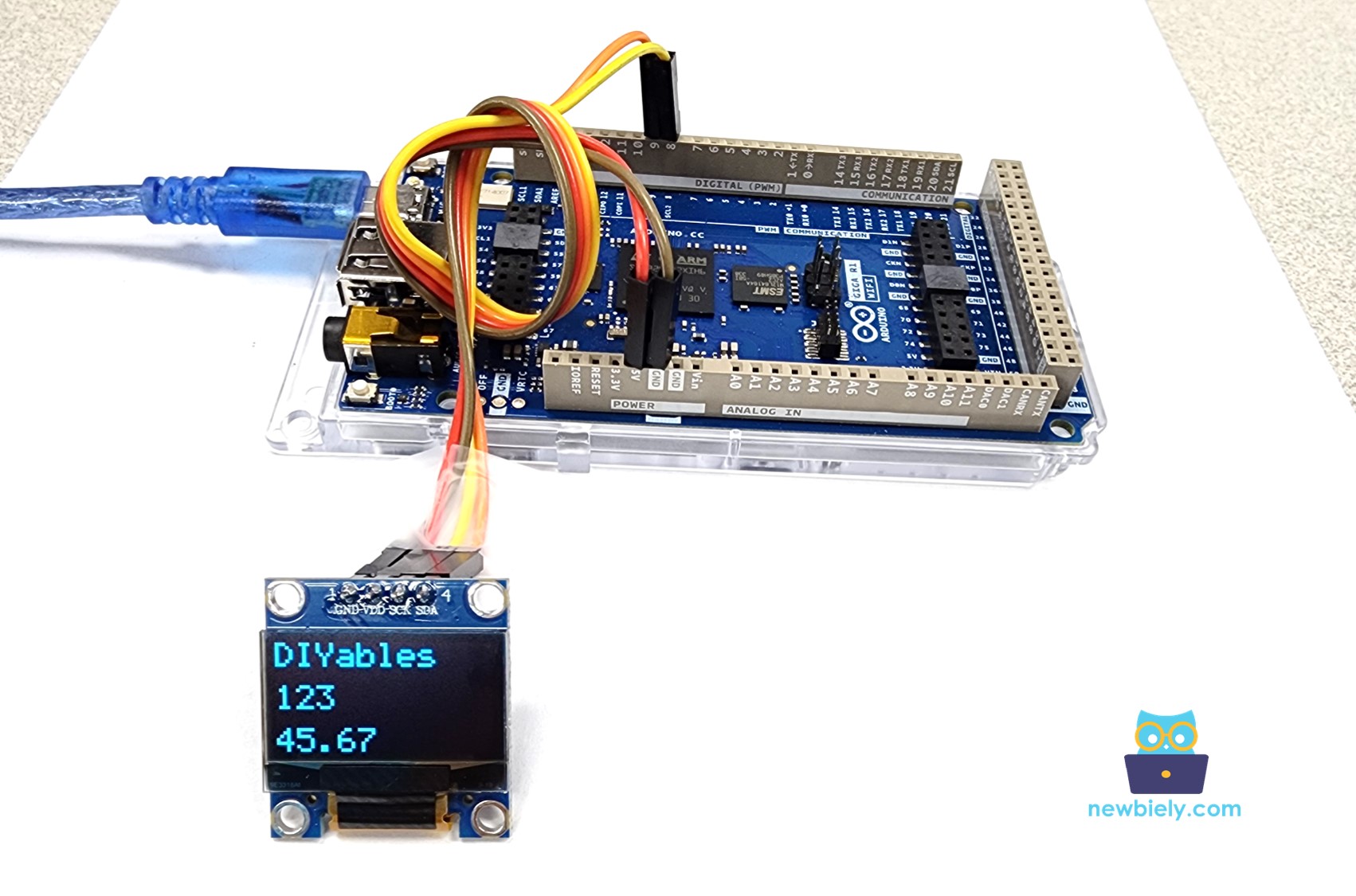
This image is created using Fritzing. Click to enlarge image
- The real wiring diagram between Arduino and OLED 128x32
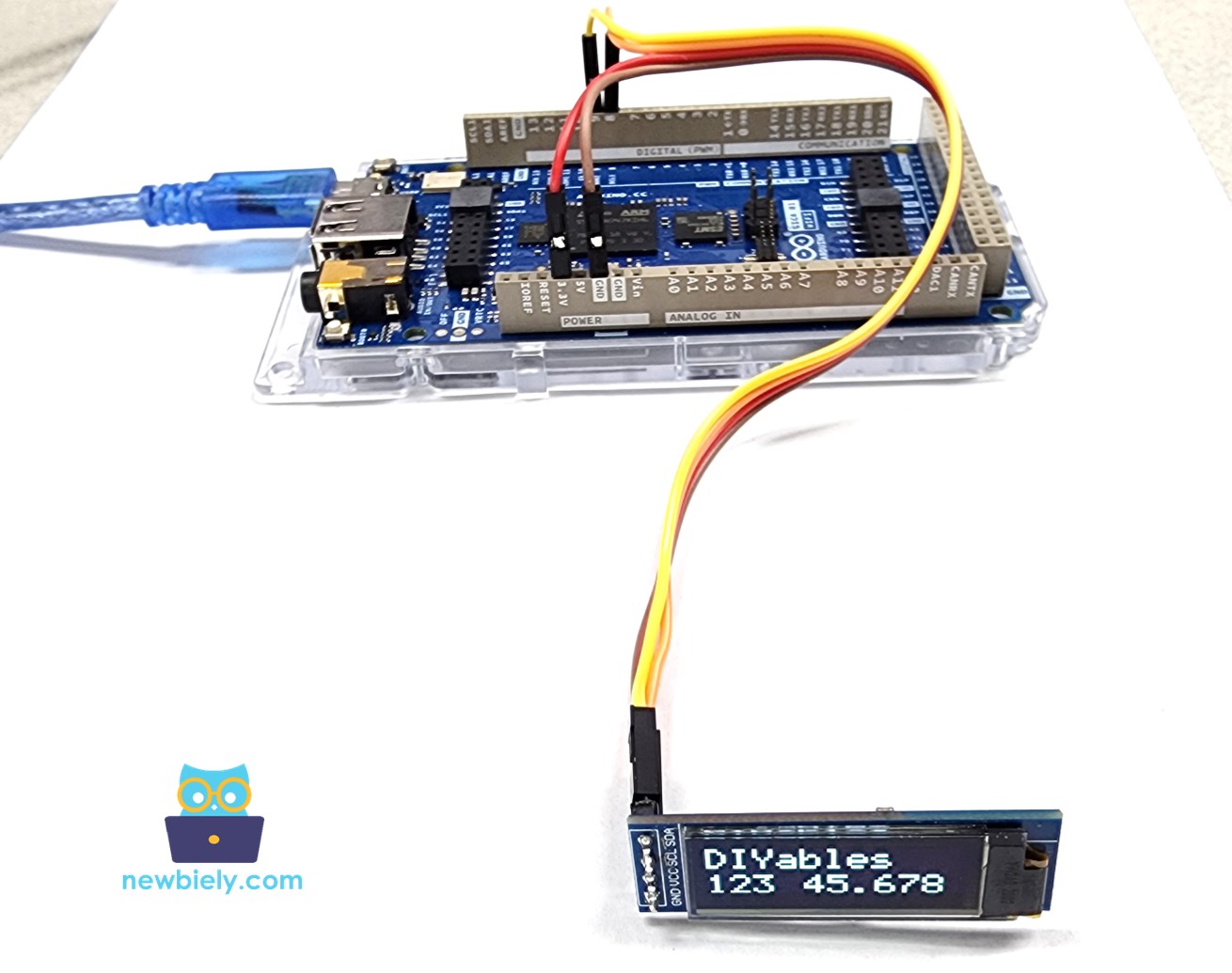
This image is created using Fritzing. Click to enlarge image
| OLED Module Pin | Arduino Giga R1 WiFi Pin |
|---|---|
| VCC | 5V |
| GND | GND |
| SDA | Pin 9 (SDA2) |
| SCL | Pin 8 (SCL2) |
If you use other Arduino boards, the I2C pin assignments differ. The Arduino Giga R1 WiFi uses pins 9 (SDA2) and 8 (SCL2) for Wire2, while Arduino Uno uses A4 (SDA) and A5 (SCL). Always verify the I2C pinout for your specific board variant to ensure proper communication establishment.
How To Use OLED with Arduino
Install SSD1306 OLED library
The Adafruit SSD1306 library provides a comprehensive graphics framework that abstracts the low-level SSD1306 controller commands into high-level drawing functions. This library handles I2C communication protocol implementation, display initialization sequences, and graphics rendering optimizations. The implementation includes font rendering, geometric drawing primitives, and bitmap display capabilities.
The library architecture separates hardware communication (SSD1306 driver) from graphics operations (GFX library), enabling code portability across different display controllers while maintaining consistent API interfaces.
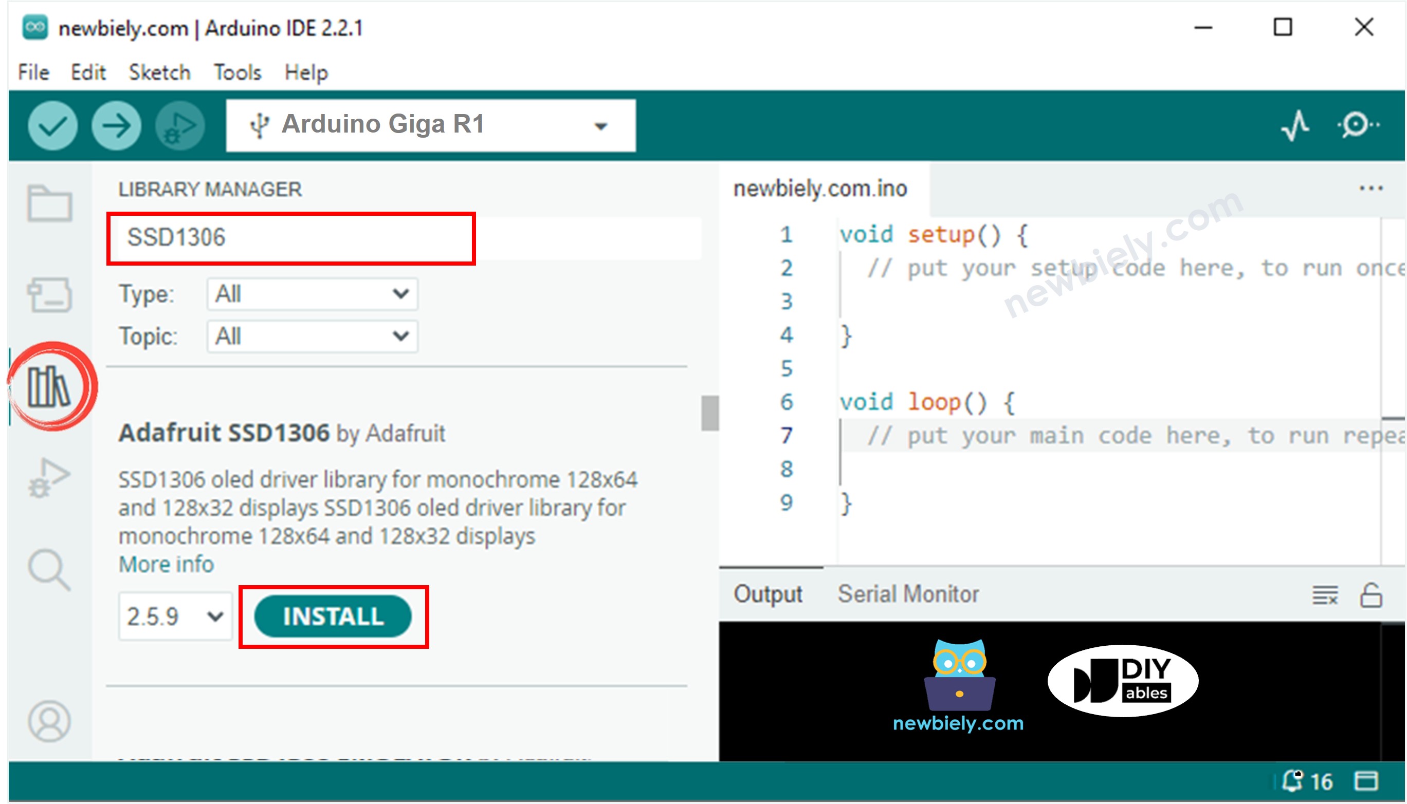
- Navigate to the Libraries icon on the left bar of the Arduino IDE.
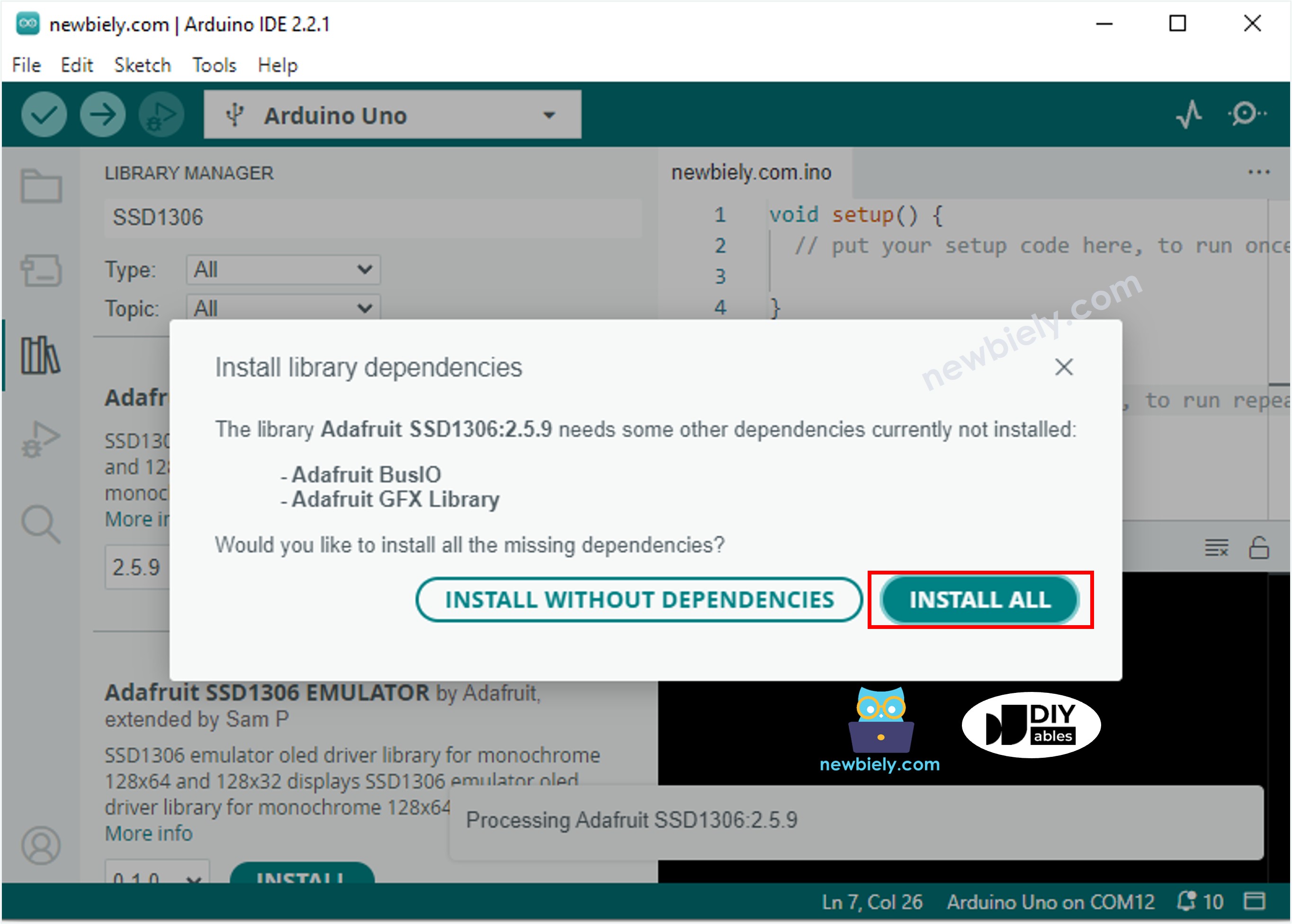
- Search "SSD1306", then find the SSD1306 library by Adafruit
- Click Install button to install the library.
- You will be asked for intalling some other library dependencies
- Click Install All button to install all library dependencies.
How to program for OLED
The following implementation demonstrates the essential structure for SSD1306 OLED control using I2C communication. The code is organized to handle hardware initialization, display configuration, and graphics rendering in a systematic approach. Key sections include library initialization, screen buffer management, and display update control.
The Adafruit_SSD1306 library abstracts the SSD1306 controller's command set, which includes over 25 different configuration commands for contrast, addressing modes, and power management. The library manages a local frame buffer in microcontroller RAM that mirrors the display contents, requiring display() calls to transfer the buffer contents to the physical OLED via I2C.
- Include library
- Define the screen size if OLED 123x64
- Define the screen size if OLED 128x32
- Declare an SSD1306 OLED object
- In setup() function, initialize OLED display
- And then you can display text, images, draw line ...
The initialization sequence configures the SSD1306 controller with optimal settings for the specified resolution. The SSD1306_SWITCHCAPVCC parameter enables the internal charge pump, allowing operation from a single 5V supply without requiring external high-voltage generation. The I2C address 0x3C is factory-set for most SSD1306 modules, though some variants use 0x3D depending on hardware configuration.
※ NOTE THAT:
From this point on, all codes are provided for OLED 128x64, but you can easily adapt for OLED 128x32 by changing the screen size and adjusts coordinates if needed
Arduino Code - Display Text on OLED
The text rendering system provides comprehensive control over font presentation and positioning. The coordinate system originates at the top-left corner (0,0), with x-axis extending right and y-axis extending down. Text baseline positioning follows standard typography conventions, with character height varying by font size multiplier.
The below are key functions for text manipulation on the OLED display:
- oled.clearDisplay(): Clears the frame buffer by setting all pixels to off state. Must call display() to update physical screen.
- oled.drawPixel(x,y, color): Sets individual pixel state at specified coordinates. Color values: SSD1306_WHITE (on) or SSD1306_BLACK (off).
- oled.setTextSize(n): Configures font scaling multiplier from 1 to 8. Size 1 = 6x8 pixels per character, size 2 = 12x16 pixels, etc.
- oled.setCursor(x,y): Positions text cursor at pixel coordinates for subsequent text output.
- oled.setTextColor(WHITE): Sets foreground text color. For monochrome displays, WHITE=pixel on, BLACK=pixel off.
- oled.setTextColor(BLACK, WHITE): Configures foreground and background colors for inverse text rendering.
- oled.println("message"): Outputs text string with automatic line advancement and word wrapping at display boundaries.
- oled.println(number): Renders numeric values in decimal format with automatic type conversion.
- oled.println(number, HEX): Displays numeric values in hexadecimal representation with "0x" prefix.
- oled.display(): Transfers complete frame buffer to OLED controller via I2C. Essential for making changes visible.
- oled.startscrollright(start, stop): Initiates hardware horizontal scrolling from specified row range, 6-pixel shift every frame.
- oled.startscrollleft(start, stop): Enables leftward scrolling with hardware timing control for smooth animation.
- oled.startscrolldiagright(start, stop): Combines horizontal and vertical scrolling for diagonal text movement effects.
- oled.startscrolldiagleft(start, stop): Creates left-diagonal scrolling animation using SSD1306 built-in scroll engine.
- oled.stopscroll(): Disables all scrolling modes and returns to static display rendering.
Performance considerations: Text rendering speed decreases with larger font sizes due to increased pixel operations. The Arduino Giga R1 WiFi's ARM Cortex-M7 core at 480 MHz provides sufficient processing power for real-time text updates without noticeable delays.
How to vertical and horizontal center align text/number on OLED
Arduino Code - Drawing on OLED
The graphics rendering system utilizes the Adafruit GFX library's primitive drawing functions optimized for monochrome displays. Drawing operations modify the frame buffer in RAM, requiring explicit display() calls to transfer changes to the physical OLED. The coordinate system maintains consistent (0,0) origin at top-left with standard Cartesian progression.
Geometric primitives include lines (Bresenham algorithm for smooth diagonal rendering), rectangles (filled and outlined variants), circles (midpoint circle algorithm), triangles, and bitmap operations. All drawing functions support pixel-level precision with automatic clipping at display boundaries to prevent buffer overflow conditions.
Arduino Code – Display Image
To render images on OLED displays, bitmap data must be converted to a byte array format compatible with the SSD1306 memory organization. The display uses a page-based addressing mode where each page represents 8 vertical pixels, requiring specific bit ordering for proper image reconstruction.
Image conversion involves several technical considerations: resolution scaling to fit display dimensions, bit depth reduction to monochrome (1-bit per pixel), and byte packing according to SSD1306 page organization. The vertical page structure means each byte represents 8 vertically-stacked pixels, with LSB at the top.
The conversion can be accomplished using this Image to Bitmap Converter tool. The process converts standard image formats (PNG, JPG, BMP) into Arduino-compatible byte arrays with proper bit ordering and PROGMEM storage directives for efficient flash memory utilization.
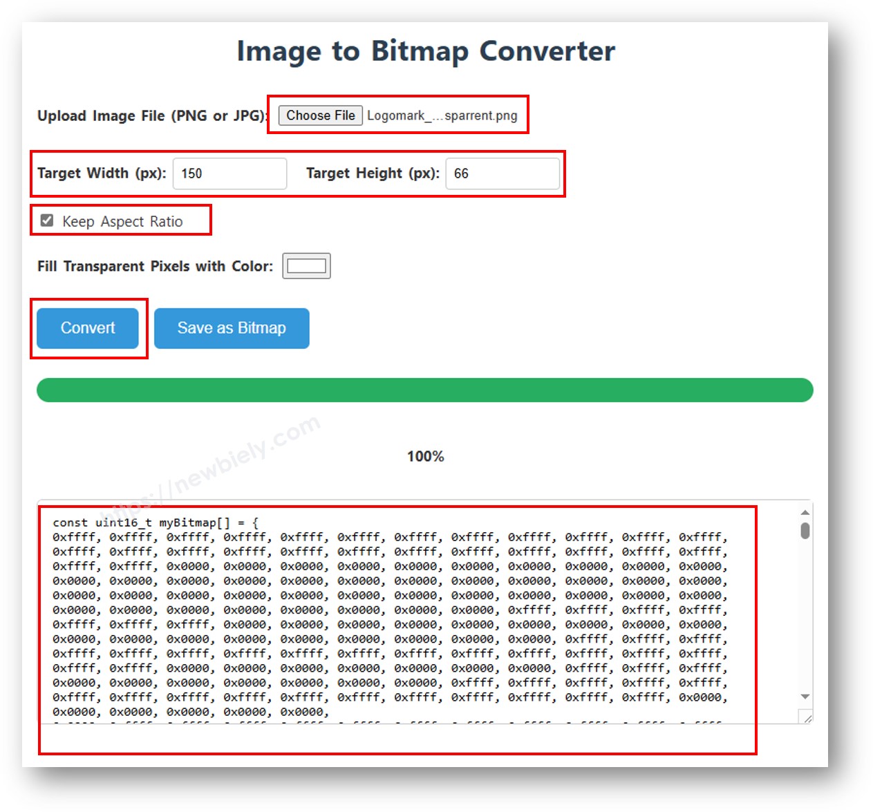
After converting, copy the generated array code and replace the ArduinoIcon array in the below implementation:
Technical considerations for bitmap display:
- Image dimensions must not exceed display resolution (128x64 or 128x32)
- Bitmap data consumes RAM during execution—large images may cause memory constraints on smaller microcontrollers
- The Arduino Giga R1 WiFi's 8MB PSRAM enables storage of multiple high-resolution bitmaps simultaneously
- Rendering speed depends on image size: 128x64 bitmap requires ~1KB transfer via I2C at 400kHz, completing in approximately 20ms
※ NOTE THAT:
- The image size should be smaller than or equal to screen size.
- If you want to adapt the above code for OLED 128x32, you need to recale image and change width/ height in oled.drawBitmap(); function
Detailed Instructions
For initial Arduino Giga R1 WiFi setup, refer to the Arduino Giga R1 WiFi Getting Started guide before proceeding.
- Install Libraries: Open Arduino IDE Library Manager and install "Adafruit SSD1306" library. Accept all dependency installations including Adafruit GFX library. This provides the complete graphics framework for OLED control.
- Connect Hardware: Wire OLED display to Arduino Giga R1 WiFi using I2C connections: VCC to 5V, GND to GND, SDA2 to Pin 9, SCL2 to Pin 8. Verify connections match pin labels on your specific OLED module.
- Configure Display: Create Adafruit_SSD1306 object with correct screen dimensions (128x64 or 128x32). Initialize with I2C address 0x3C and internal charge pump enabled for single-supply operation.
- Upload Code: Select appropriate example code (text, drawing, or image display) and upload to Arduino Giga R1 WiFi. Compilation should complete without errors if libraries are properly installed.
- Verify Operation: Power on the system and observe OLED display for expected output. Text should appear crisp and readable, graphics should render smoothly, and images should display without distortion.
- Monitor Serial Output: Open Serial Monitor at 9600 baud to view initialization status messages. Successful operation shows "SSD1306 allocation succeeded" or similar confirmation messages.
- Test I2C Communication: If display remains blank, run I2C scanner code to verify device detection at address 0x3C. No response indicates wiring issues or hardware failure.
Technical Note: The SSD1306 controller includes power-saving features that automatically reduce current consumption during static display periods. Dynamic content updates may draw up to 20mA, while static text typically consumes 8-12mA depending on pixel density.
Serial Monitor Output
Application/Project Ideas
Environmental Monitoring Station: Implement a real-time sensor display system showing temperature, humidity, and air quality readings on OLED with automatic data logging. The Arduino Giga R1 WiFi's dual-core architecture enables simultaneous sensor polling and display updates while maintaining responsive user interface.
Industrial Process Indicator: Create a compact status display for manufacturing equipment showing operational parameters, alarm conditions, and production metrics. The OLED's high contrast visibility and wide viewing angle make it ideal for industrial environments with varying lighting conditions.
IoT Device Dashboard: Develop a local information display for WiFi-connected sensors showing network status, data transmission rates, and cloud connectivity indicators. Integration with the Arduino Giga R1 WiFi's built-in WiFi capabilities enables real-time remote monitoring and configuration.
Portable Instrumentation Display: Build a handheld measurement device interface displaying sensor readings, calibration status, and data storage information. The OLED's low power consumption extends battery life in portable applications, while fast refresh rates support real-time measurement display.
Laboratory Equipment Interface: Design a compact control panel for scientific instruments showing experimental parameters, timing information, and system status indicators. The precise pixel control enables creation of custom symbols, graphs, and technical notation display.
Automation System HMI: Implement a human-machine interface for home or building automation displaying zone status, scheduling information, and energy consumption data. The Arduino Giga R1 WiFi's processing power supports complex graphics rendering for intuitive user interfaces.
Applications can be scaled from single-display systems to multi-node networks sharing display data via I2C, SPI, or wireless protocols. Consider data logging to SD cards for historical trend analysis and system diagnostics.
Video Section
The accompanying video demonstrates the complete hardware assembly process and live code execution for Arduino Giga R1 WiFi OLED integration. It covers library installation procedures, I2C wiring verification, and real-time display output for text, graphics, and image rendering examples. The video shows expected serial monitor output during initialization and troubleshooting steps for common connection issues.
Challenge Yourself
Challenge: Implement a multi-page menu system with button navigation and dynamic content updates. Add three pushbuttons to cycle through different display screens (sensors, settings, status) with smooth transitions and cursor highlighting.
Challenge: Create a real-time graph plotting system that displays sensor data over time with automatic scaling and axis labels. Utilize the Arduino Giga R1 WiFi's expanded memory to store historical data points and implement scrolling graph functionality.
Challenge: Design a wireless display node that receives data from other Arduino devices via WiFi and presents multiple sensor readings in a dashboard format. Include network status indicators, data freshness timestamps, and automatic reconnection handling.
Challenge: Develop a custom font rendering system that displays large numeric values using bitmap fonts stored in PROGMEM. Implement decimal point positioning and units display for measurement applications requiring high visibility.
Challenge: Build an image slideshow system that cycles through multiple bitmap images stored in the Arduino Giga R1 WiFi's flash memory. Add fade transitions between images and implement manual/automatic advancement controls with timing adjustments.
These challenges leverage the Arduino Giga R1 WiFi's processing power, memory capacity, and connectivity features to create sophisticated display applications beyond basic text output.
OLED Troubleshooting
If OLED does not display content, systematic diagnosis will identify the root cause. Common failure modes include communication protocol errors, power supply issues, and hardware connection problems.
Perform this diagnostic sequence:
Verify Physical Connections: Confirm wiring matches the I2C pinout specification—Arduino Giga R1 WiFi Pin 9 (SDA2) to OLED SDA, Pin 8 (SCL2) to OLED SCL, 5V to VCC, GND to GND. Loose connections cause intermittent operation or complete communication failure.
Confirm SSD1306 Driver Compatibility: Ensure your OLED module uses the SSD1306 controller IC. Some visually similar displays use SH1106 or other controllers requiring different initialization commands and addressing modes.
Check I2C Address Configuration: Run the I2C Address Scanner to detect connected devices and verify the OLED responds at the expected address (typically 0x3C). Address conflicts with other I2C devices can prevent proper communication establishment.
Expected I2C scanner output for properly connected OLED:
Additional Diagnostic Steps:
- Power Supply Verification: Measure VCC pin voltage with multimeter—should read 4.8V-5.2V under load
- Signal Integrity Check: Verify I2C signal levels with oscilloscope if available—both lines should show clean digital transitions
- Library Version Compatibility: Ensure latest Adafruit SSD1306 library version is installed, as older versions may have initialization bugs
- Memory Allocation Verification: Check that oled.begin() returns true, indicating successful frame buffer allocation in RAM
Failure to detect the device at address 0x3C indicates hardware connection problems, power supply issues, or defective OLED module requiring replacement.