Arduino Giga R1 WiFi Control Pump
This guide covers pump control implementation with the Arduino Giga R1 WiFi using relay-based switching. You'll implement a reliable 12V pump control system using relay isolation and Arduino GPIO control.
This tutorial demonstrates pump control including safety considerations for high-current loads, proper electrical isolation using relays, and structured code for reliable operation. You'll learn to handle the electrical requirements of 12V DC pumps and create timing-based control sequences.
Hardware Preparation
Or you can buy the following kits:
| 1 | × | DIYables Sensor Kit (18 sensors/displays) |
Additionally, some of these links are for products from our own brand, DIYables .
Overview of 12V Pump
12V DC pumps are centrifugal or positive-displacement devices for fluid transfer. They typically draw 0.5-3A current and feature simple two-wire control suitable for relay switching. Most 12V pumps operate as self-priming units capable of generating 1-5 meters of head pressure.
Integration with the Arduino Giga R1 WiFi requires relay-based switching because the pump's current draw (1-3A) far exceeds the Arduino's GPIO current limit (20mA maximum). This provides electrical isolation between the Arduino's low-voltage control circuits and the pump's high-current 12V power circuit.
Pinout
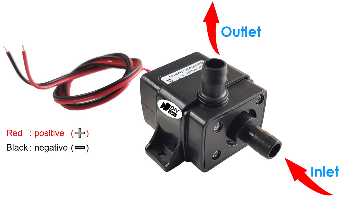
The pump pinout defines the electrical interface between the power supply and the motor assembly. Correct polarity connection is critical for proper rotation direction and to prevent damage to internal components.
12V Pump usually has two pins:
- Negative (-) pin (black): DC return path, 0V reference. Connects to GND of the 12V DC power supply to complete the current return path through the motor windings.
- Positive (+) pin (red): DC power input, +12V nominal (10-15V acceptable range). Connects to the positive terminal of the 12V DC power supply through the relay's normally-open contacts.
Electrical Note: Reverse polarity connection will cause the pump to rotate backward, potentially reducing efficiency or causing cavitation in centrifugal designs. Most brushed DC pumps can handle brief polarity reversal without permanent damage, but sustained reverse operation may cause premature brush wear.
How to Control Pump
Pump control with the Arduino Giga R1 WiFi requires relay-based switching due to the significant current mismatch between Arduino GPIO capabilities (20mA maximum) and pump operating current (1-3A typical). The relay acts as an electrically-isolated switch, allowing the Arduino's low-voltage 5V digital output to control the high-current 12V pump circuit safely.
When the Arduino GPIO output is HIGH (5V), the relay coil energizes, closing the normally-open contacts and connecting the pump to the 12V power supply. When the GPIO output is LOW (0V), the relay coil de-energizes, opening the contacts and disconnecting power from the pump. This switching arrangement provides complete electrical isolation between the Arduino's microcontroller circuitry and the pump's power circuit.
The relay switching approach offers several advantages: electrical noise isolation prevents pump switching transients from affecting Arduino operation, current isolation protects the Arduino from pump overcurrent conditions, and voltage isolation allows different supply voltages for control logic and pump operation. Additionally, relay contacts can handle inrush current spikes that occur when the pump motor starts.
For reliable operation, consider the relay's contact rating (must exceed pump current), coil voltage compatibility (5V or 12V), and switching speed requirements for your application. If you do not know about relay operation, electrical characteristics, and Arduino programming techniques, learn about relay implementation in the Arduino - Relay tutorial before proceeding.
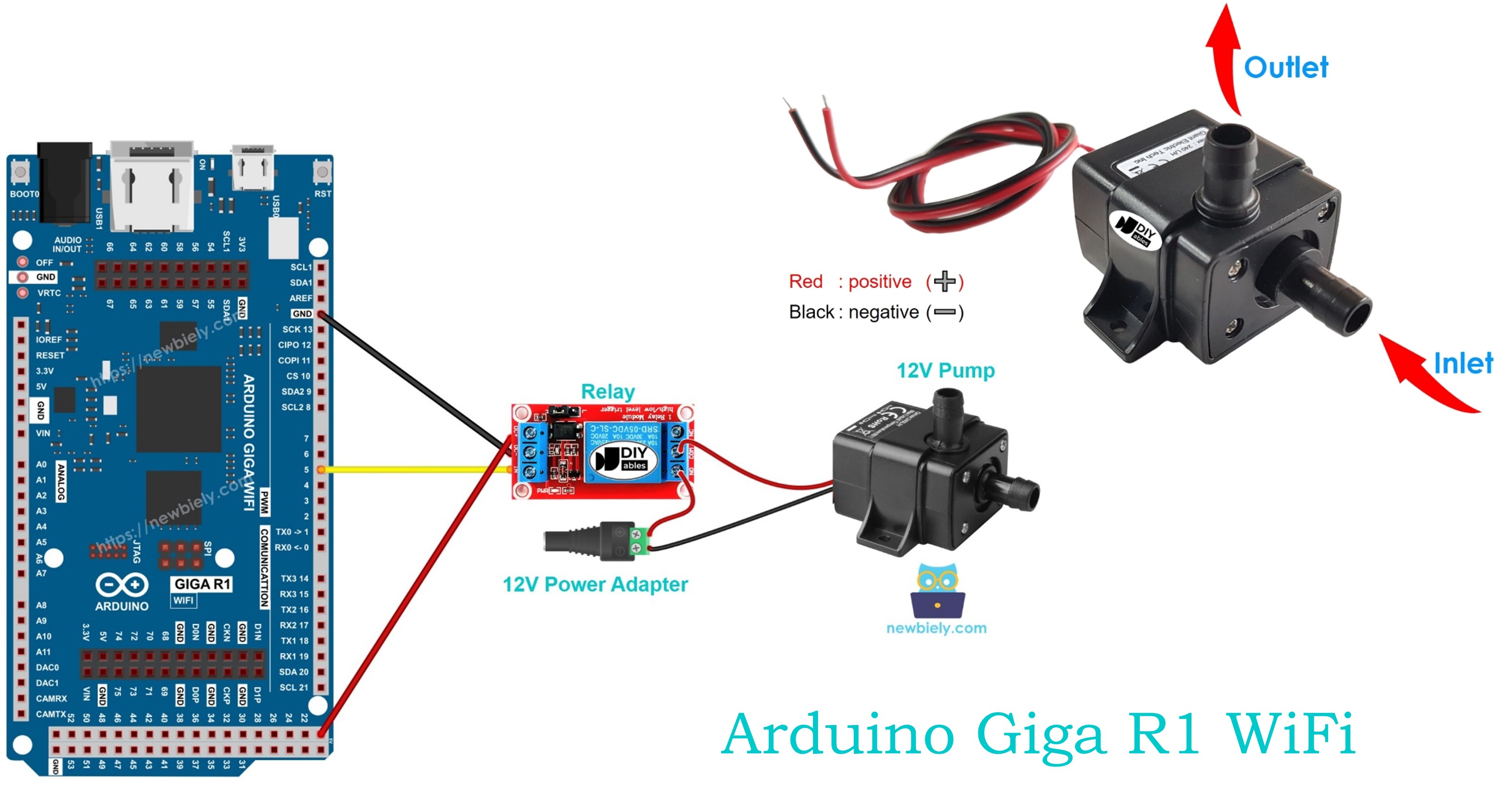
Wiring Diagram
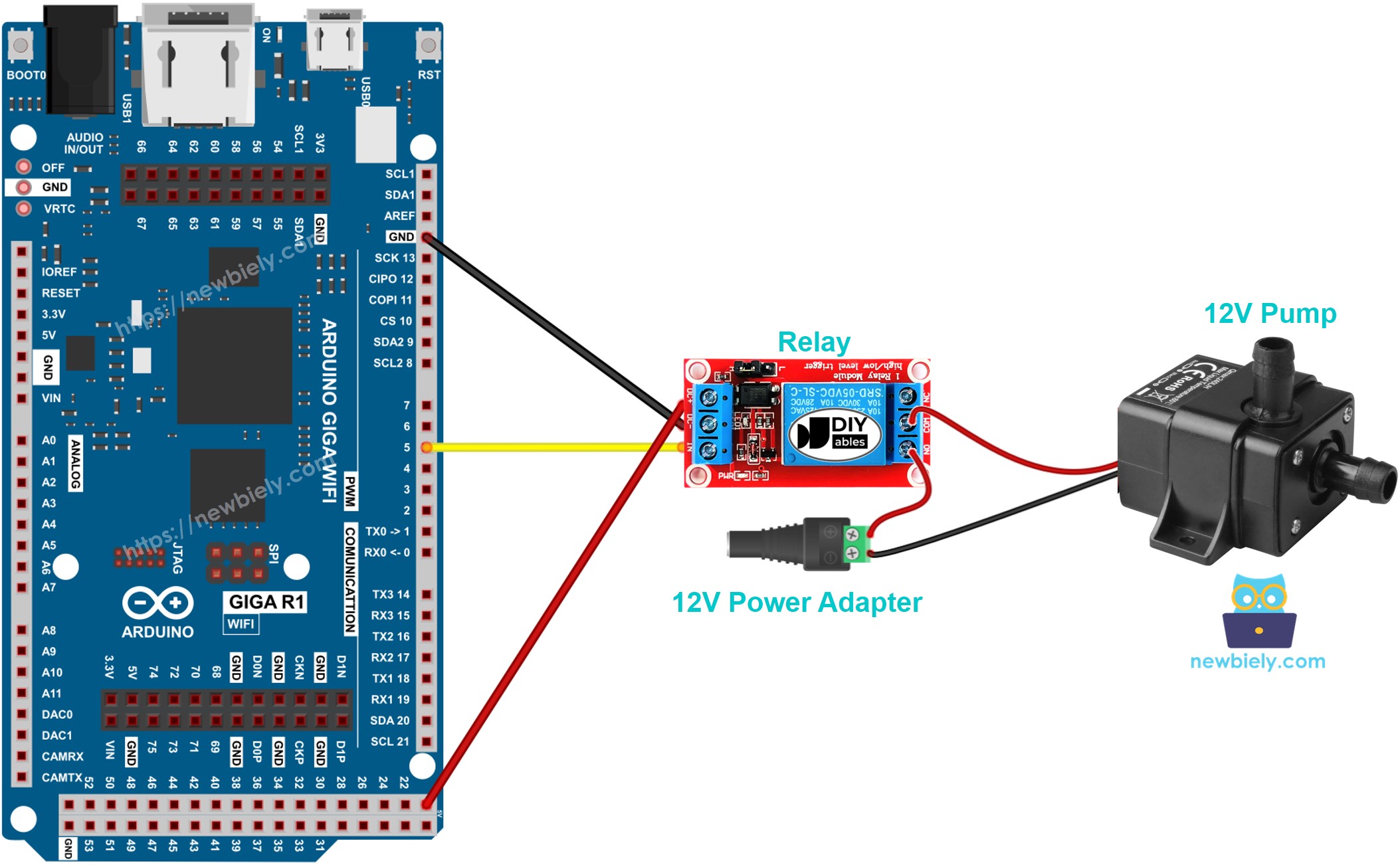
This image is created using Fritzing. Click to enlarge image
The wiring diagram illustrates the complete electrical connection between the Arduino Giga R1 WiFi, relay module, pump, and power supply. This configuration provides proper electrical isolation and current handling for safe pump operation.
Electrical Note: The diagram above shows the minimum viable connection for pump control demonstration. For production or extended use, consider adding a flyback diode (1N4007 or equivalent) across the pump terminals to suppress back-EMF spikes during switching, and implement proper wire gauge selection (18-16 AWG) for the 12V pump circuit to handle current without voltage drop.
Power supply requirements include a 12V DC adapter rated for at least 150% of the pump's steady-state current to accommodate inrush current during startup. The Arduino Giga R1 WiFi can be powered via USB during development or through the DC barrel jack (7-20V input) for standalone operation. Ensure common ground connection between the relay module and Arduino for reliable switching operation.
| Component Pin | Arduino Giga R1 WiFi Pin | Function |
|---|---|---|
| Relay VCC | 5V | Relay coil power supply |
| Relay GND | GND | Ground reference |
| Relay IN | Digital Pin 7 | Control signal input |
| Pump (+) | Relay NO Common | Switched 12V power |
| Pump (-) | 12V Supply GND | Power return path |
| 12V Supply (+) | Relay NO | Power source |
| 12V Supply (-) | System GND | Common ground |
Arduino Code
The following implementation demonstrates relay-controlled pump operation using timed switching cycles. The code is structured to handle pump startup delays and provides clear state indication through the serial monitor. Key sections include relay initialization, timing control using millis() for non-blocking operation, and state management for reliable switching.
The Arduino's digitalWrite() function controls the relay state by asserting HIGH (5V) to energize the relay coil and close the pump circuit, or LOW (0V) to de-energize the relay and disconnect the pump. The implementation uses interval-based timing rather than delay() functions to maintain responsive program execution and enable future expansion for sensor inputs or communication protocols.
This basic implementation establishes the fundamental pump control pattern: initialize the relay control pin, implement timing-based state switching, and provide serial feedback for monitoring operation. The 5-second ON/OFF cycle provides visible demonstration of pump operation while allowing time to observe flow characteristics and relay switching behavior.
Detailed Instructions
Prerequisites: Arduino IDE installed and the Giga R1 WiFi board package configured. Refer to the Getting Started guide for setup instructions.
- Connect Hardware: Wire the relay module to Arduino pin 7, VCC, and GND as shown in the wiring diagram. Connect the pump through the relay's normally-open contacts to the 12V power supply. Verify all connections before applying power.
- Prepare Power Supply: Connect the 12V adapter to the DC power jack and verify 12V output with a multimeter. Ensure the adapter current rating exceeds the pump's specifications by at least 50% to handle inrush current.
- Open Arduino IDE: Launch the Arduino IDE and select "Arduino Giga R1 WiFi" from the board manager. Verify the correct COM port is selected for USB communication with the development board.
- Load Code: Copy the pump control code and paste it into a new Arduino sketch. Review the pin assignment (pin 7) and timing parameters (5000ms intervals) to ensure they match your requirements.
- Upload Program: Click the Upload button to compile and transfer the code to the Arduino Giga R1 WiFi. Monitor the console output for compilation errors or upload failures, which typically indicate board selection or port assignment issues.
- Monitor Operation: Open the Serial Monitor at 9600 baud to observe pump state messages. The output should alternate between "Pump is ON" and "Pump is OFF" at 5-second intervals, corresponding to audible relay clicking and visible pump operation.
- Verify Pump Function: Confirm the pump operates during ON cycles by observing fluid flow, pressure buildup, or motor operation sounds. Check that the pump completely stops during OFF cycles with no residual rotation or flow.
Technical Note: If the pump fails to operate, verify relay contact closure using a multimeter across the normally-open terminals during the ON cycle. Insufficient 12V supply current or incorrect relay wiring are common failure modes. The relay should audibly click during each state transition.
Serial Monitor Output
Application Ideas
Automated Irrigation System: Implement soil moisture-triggered irrigation using the Arduino Giga R1 WiFi's analog inputs to monitor capacitive soil sensors. The dual-core architecture enables simultaneous WiFi data logging and real-time pump control with precise timing for optimal plant watering schedules.
Aquarium Water Circulation: Create a programmable water circulation system with variable duty cycles for different aquarium zones. The Arduino Giga R1 WiFi's timer peripherals provide precise control for wave generation patterns, while serial communication enables integration with pH and temperature monitoring systems.
Automatic Refill System: Develop a level-controlled refill mechanism using ultrasonic or float sensors connected to the Arduino's digital inputs. The integrated WiFi capability allows remote monitoring of water levels and pump operation status through web interfaces or mobile applications.
Cooling System Control: Build a thermal management system using temperature sensors and variable pump operation based on thermal load. The Arduino Giga R1 WiFi's PWM capabilities enable relay-based variable-speed control through duty cycle modulation for precise flow rate adjustment.
Hydroponics Nutrient Distribution: Construct a multi-zone nutrient delivery system with timed pump sequences for different growth stages. The generous memory capacity supports complex scheduling algorithms and nutrient concentration calculations for optimized plant growth.
Water Feature Control: Design fountain or water feature control with programmable patterns, synchronized lighting, and remote activation. The Arduino Giga R1 WiFi's multiple timer peripherals enable complex choreographed sequences while WiFi connectivity provides visitor interaction capabilities.
Video Section
The accompanying video demonstrates the complete hardware assembly and live code execution. It covers relay connection verification, pump priming procedures, and proper startup sequence timing. The demonstration shows expected serial monitor output synchronized with audible relay operation and visible pump flow, providing verification of correct implementation.
Challenge Yourself Section
Challenge: Implement moisture-triggered automatic irrigation with pump runtime limiting to prevent system flooding. Add a soil moisture sensor input and modify the control logic to activate the pump only when moisture falls below a threshold, with maximum continuous runtime protection.
Challenge: Create a dual-pump alternating system for redundancy and load balancing. Configure two pump-relay combinations that alternate operation cycles to extend pump lifetime and provide backup capability if one unit fails.
Challenge: Build a remote-controlled pump system using the Arduino Giga R1 WiFi's integrated WiFi capability. Implement a web server interface that displays pump status and accepts ON/OFF commands through HTTP requests for IoT integration.
Challenge: Design a flow rate monitoring system by adding a flow sensor to measure pump performance. Calculate and log flow rates, total volume transferred, and pump efficiency metrics while maintaining the basic relay control functionality.
Challenge: Develop a schedule-based irrigation controller with multiple daily watering periods. Implement real-time clock functionality using the Arduino's internal RTC and create a user interface for programming watering schedules, duration, and frequency parameters.