Arduino Giga R1 WiFi Relay
This guide covers relay control with the Arduino Giga R1 WiFi for high-voltage device switching. The relay serves as a bridge between low-voltage microcontroller signals and high-power devices.
This tutorial demonstrates relay integration through a practical LED strip control example. You'll implement hardware connections, understand relay operating modes, and write control code adaptable for any high-power device.
Hardware Preparation
Or you can buy the following kits:
| 1 | × | DIYables Sensor Kit (18 sensors/displays) |
Additionally, some of these links are for products from our own brand, DIYables .
Overview of Relay
A relay is an electrically operated switch designed for programmatic control of high-voltage and high-current devices through low-voltage control signals. The device operates on electromagnetic principles: a small control current through a coil generates a magnetic field that physically moves switch contacts, enabling or disabling power flow to the connected load. This electromagnetic isolation allows microcontrollers like the Arduino Giga R1 WiFi to safely control devices operating at voltages and currents that would otherwise destroy digital GPIO pins.
Modern relay modules typically operate with 5V or 3.3V control signals, making them directly compatible with Arduino digital outputs. The switching capacity varies significantly by relay type — common modules handle 10A at 250V AC or 10A at 30V DC, though industrial relays can switch much higher loads. Contact resistance is typically less than 100mΩ when closed, and isolation voltage between control and switching circuits often exceeds 1500V AC, providing robust protection against voltage transients and ground potential differences.
Relay modules designed for microcontroller integration often include additional circuitry: flyback diodes to suppress inductive kickback, LED status indicators, and optoisolated inputs for enhanced electrical isolation. Some modules feature jumper-selectable trigger levels (HIGH or LOW active) and support both normally-open (NO) and normally-closed (NC) operation modes. The switching time for typical electromechanical relays ranges from 5-15 milliseconds, which is adequate for most Arduino Giga R1 WiFi applications but may be too slow for high-frequency switching requirements.
When integrating relays with the Arduino Giga R1 WiFi, consider the control signal current requirements. Most relay modules draw 15-80mA from the control pin, well within the Arduino's 40mA maximum pin current when properly designed. For applications requiring multiple relay control, the Arduino Giga R1 WiFi's expanded GPIO count and dual-core architecture enable sophisticated switching patterns while maintaining responsive system operation. The built-in WiFi capability also supports remote relay control through MQTT, HTTP APIs, or custom networking protocols.
WARNING
When you are making projects that are connected to mains voltage, you need to know what you are doing, otherwise, you may shock yourself. This is a serious topic, and we want you to be safe. If you're NOT 100% sure what you are doing, do yourself a favor and don't touch anything. Ask someone who knows!
Although some kinds of relays support both DC and AC devices, We highly recommend you to use a DC device (≤24V) for testing.
Relay Pinout
The pinout configuration determines how the relay integrates with both the Arduino Giga R1 WiFi control signals and the high-voltage device being switched. Correct wiring is essential — an incorrect connection between control and switched circuits can damage the Arduino or create dangerous electrical conditions.
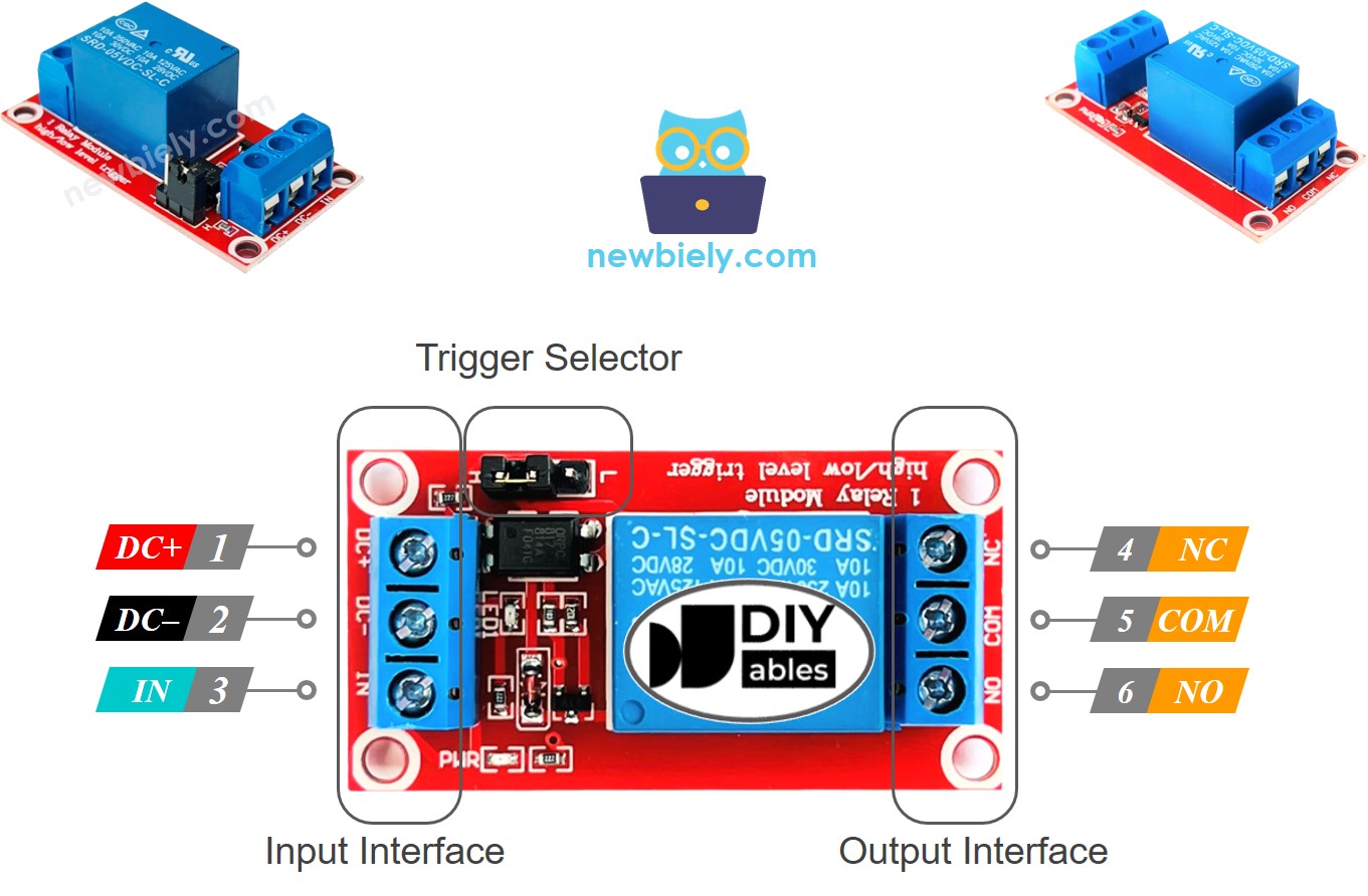
Relay modules feature two electrically isolated pin groups: the low-voltage control input and the high-voltage switching output. Each group operates independently with galvanic isolation between them.
Control Input Pins (Low Voltage Side):
- DC- Pin: Ground reference (0V). Connects to Arduino Giga R1 WiFi GND to establish common potential between control circuits. Current path for relay coil return.
- DC+ Pin: Positive supply voltage (typically +5V). Connects to Arduino Giga R1 WiFi 5V output to power relay coil. Current consumption ranges from 15-80mA depending on relay specifications.
- IN Pin: Control signal input (digital logic level). Connects to Arduino GPIO pin to provide switching commands. Input threshold typically 1.4V (LOW) to 2.0V (HIGH) for 5V operation.
Switching Output Pins (High Voltage Side):
- COM Pin: Common terminal for switched circuit. Functions as the movable contact point in both normally-open and normally-closed configurations. Always carries the switched current.
- NO Pin: Normally Open terminal. Connected to COM when relay coil is energized. Used for devices that should activate when the Arduino pin goes HIGH (in HIGH-trigger mode).
- NC Pin: Normally Closed terminal. Connected to COM when relay coil is de-energized. Used for devices that should activate when the Arduino pin goes LOW, or for fail-safe circuits.
The Arduino Giga R1 WiFi's 3.3V GPIO outputs are compatible with most 5V relay modules due to the higher logic threshold. However, verify your specific relay module's input specifications — some modules may require level shifting for reliable operation.
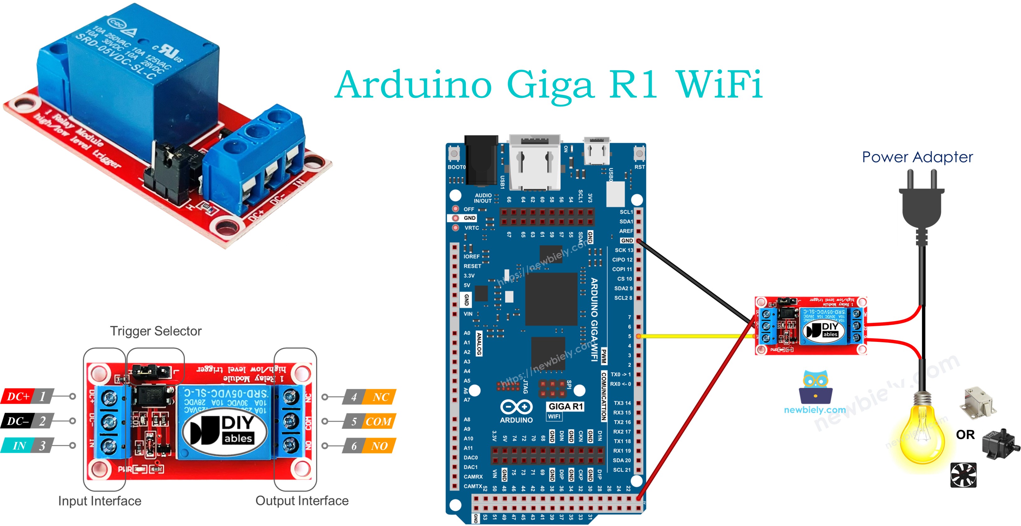
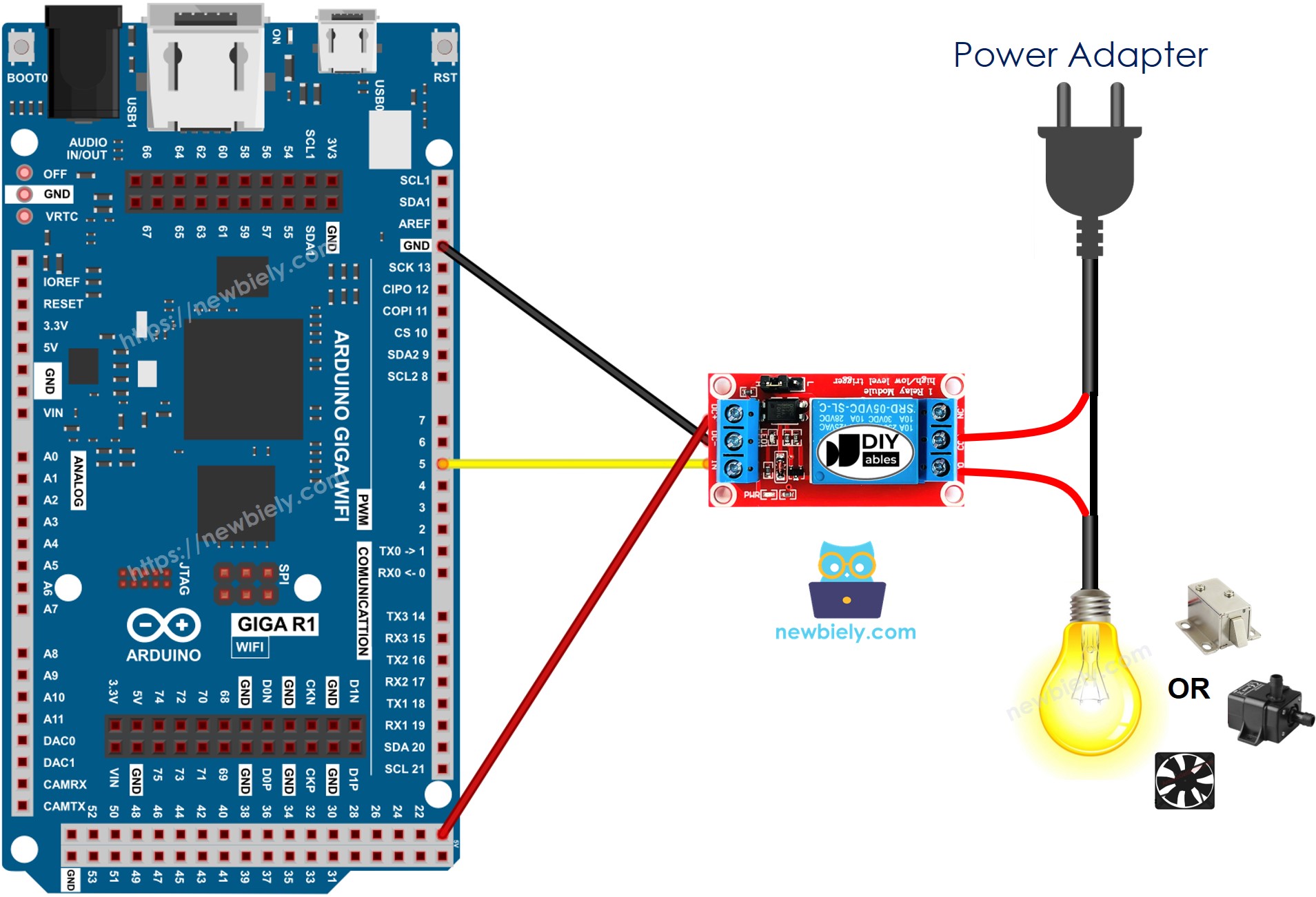
Wiring Diagram
The wiring implementation connects the Arduino Giga R1 WiFi's digital output to the relay control input while maintaining proper electrical isolation between control and switching circuits. This configuration demonstrates normally-open mode operation with HIGH-level triggering.
Electrical Note: The diagram above shows the minimum viable connection for development and testing. For production applications or extended operation, consider adding a flyback diode across the relay coil (if not already integrated) and implementing proper wire gauge selection based on the switched load current requirements.
This image is created using Fritzing. Click to enlarge image
| Component Pin | Arduino Giga R1 WiFi Pin |
|---|---|
| DC- | GND |
| DC+ | 5V |
| IN | Digital Pin 3 |
The high-voltage connections (COM, NO, NC) depend on your specific load and operating mode requirements. For this LED strip example, connect the LED strip's positive input to the relay's NO terminal and the relay's COM terminal to the 12V power supply positive output. The LED strip's negative input connects directly to the 12V power supply ground. This configuration creates a normally-open switch that energizes the LED strip when the Arduino Giga R1 WiFi drives pin 3 HIGH.
Power supply considerations: The relay coil draws approximately 70mA from the Arduino's 5V rail. Ensure your USB connection or external power supply can provide adequate current for both the Arduino Giga R1 WiFi (typical 200mA) and the relay coil. For systems controlling multiple relays, calculate total current draw and use an external 5V supply if necessary.
How To Program For Relay
The relay control implementation configures an Arduino Giga R1 WiFi GPIO pin as a digital output and uses digitalWrite() commands to switch the relay state. The programming approach follows standard digital I/O patterns with specific timing considerations for relay mechanical switching delays.
Relay control requires initialization of the GPIO pin to output mode and careful management of switching timing to account for the relay's mechanical response characteristics. The electromagnetic coil requires several milliseconds to fully energize or de-energize, during which the switch contacts may bounce or remain in an intermediate state. Proper code design accounts for these physical limitations.
The following implementation demonstrates basic relay control using digital pin 3. Configure the pin for output operation during setup(), then use digitalWrite() commands to control relay state. The HIGH state energizes the relay coil (assuming HIGH-trigger mode), closing the NO contact to COM and opening the NC contact. The LOW state de-energizes the coil, returning contacts to their default positions.
Configure pin for relay control:
De-energize relay (open circuit in normally-open mode):
Energize relay (closed circuit in normally-open mode):
For applications requiring precise timing, implement delays between state changes to ensure complete mechanical switching. Typical relay switching time is 5-15 milliseconds, though some applications may require longer settling periods to eliminate contact bounce effects.
Arduino Code
Detailed Instructions
For initial Arduino Giga R1 WiFi setup, refer to the Arduino Giga R1 WiFi Getting Started guide before proceeding with relay integration.
- Connect Hardware: Wire the relay module control inputs to the Arduino Giga R1 WiFi according to the pinout diagram. Verify DC+/DC-/IN connections are correct and secure. Double-check high-voltage connections use proper wire gauge and insulation.
- Open Arduino IDE: Launch the Arduino IDE and ensure the Arduino Giga R1 WiFi board package is selected from Tools > Board menu. Verify the correct COM port is selected for your development board connection.
- Load Code: Copy the provided relay control code into a new Arduino IDE sketch. The code implements a simple blinking pattern that cycles the relay every 3 seconds, providing clear visual feedback through the connected LED strip.
- Upload Program: Click the Upload button to compile and transfer the code to the Arduino Giga R1 WiFi. Monitor the upload progress and verify successful completion without errors. The board will automatically reset and begin code execution.
- Verify Operation: Observe the LED strip switching on and off in 3-second intervals. You should hear audible clicking from the relay contacts and see the LED strip responding synchronously. The built-in LED on the Arduino board may also indicate the relay state.
- Monitor Serial Output: Open the Serial Monitor at 9600 baud to view relay state change messages. The output displays timestamps and current relay status, useful for debugging timing issues or verifying code execution flow.
- Test Manual Control: Modify the delay values in the code to change switching frequency. Upload the modified code to verify the relay responds to different timing patterns and confirm reliable switching operation.
Technical Note: The relay switching creates brief voltage transients that may affect sensitive circuits. If integrating with analog sensors or precision timing applications, consider implementing proper decoupling capacitors and physical separation between switching and measurement circuits. The Arduino Giga R1 WiFi's dual-core architecture can isolate relay control tasks from time-critical operations using the secondary processor core.
Serial Monitor Output
Application/Project Ideas
Industrial Process Control: Implement automated equipment sequencing for manufacturing lines or chemical processes. The Arduino Giga R1 WiFi's dual-core processor enables complex interlocking logic while the WiFi connectivity supports integration with SCADA systems and remote monitoring platforms.
Smart Home Automation: Control household appliances, lighting circuits, and HVAC systems through web interfaces or mobile applications. The Arduino Giga R1 WiFi's networking capabilities enable voice assistant integration and scheduling functionality with cloud-based home automation platforms.
Agricultural Irrigation System: Automate pump control, valve sequencing, and fertilizer injection based on sensor feedback and timing schedules. The expanded memory capacity supports sophisticated irrigation algorithms while WiFi connectivity enables remote monitoring and climate data integration.
Backup Power Transfer: Implement automatic transfer switches for backup generator systems or battery inverters. The Arduino Giga R1 WiFi's reliable operation and multiple GPIO pins support comprehensive power monitoring with fail-safe relay control for critical load management.
Laboratory Equipment Control: Automate test equipment, sample handling systems, and environmental chambers with precise timing and data logging. The dual-core architecture separates real-time control tasks from data acquisition, while USB host capability supports direct connection to measurement instruments.
Energy Management System: Control load shedding, peak demand management, and renewable energy switching for commercial buildings. The Arduino Giga R1 WiFi's networking features enable integration with utility demand response programs and building management systems for optimized energy consumption.
Video Section
The accompanying video demonstrates the complete hardware assembly process and live code execution for Arduino Giga R1 WiFi relay control. It covers proper wiring techniques for both control and switching circuits, relay module configuration selection, and troubleshooting common connection issues. The video shows expected relay clicking sounds and LED strip response timing to help verify correct system operation.
Challenge Yourself
Challenge: Implement a multi-zone lighting controller that operates 4 different light circuits with individual timing schedules and manual override capabilities through serial commands.
Challenge: Create an automatic room occupancy system that turns lights on when motion is detected and turns them off 30 seconds after motion stops. Integrate with the Arduino - Motion Sensor tutorial and add twilight sensor input to prevent daytime operation.
Challenge: Build a WiFi-controlled power outlet system with individual relay control through a web interface. Implement current monitoring for each outlet and automatic shutdown on overcurrent conditions. Utilize the Arduino Giga R1 WiFi's networking stack for HTTP server functionality.
Challenge: Design a backup power transfer controller that automatically switches between main power and generator input. Include voltage monitoring, generator start sequencing, and load prioritization with graceful shutdown capabilities during extended outages.
Challenge: Develop a greenhouse environmental control system that manages grow lights, circulation fans, and irrigation pumps based on temperature, humidity, and soil moisture sensors. Implement data logging to SD card and remote monitoring through MQTT connectivity for agricultural automation applications.