Arduino Giga R1 WiFi Joystick
This guide covers analog joystick integration with the Arduino Giga R1 WiFi. The tutorial walks through two-axis analog input processing, button handling, and practical conversion techniques for control systems.
This tutorial demonstrates analog coordinate reading, digital button state detection, and value conversion for directional control and servo positioning.
Hardware Preparation
Or you can buy the following kits:
| 1 | × | DIYables Sensor Kit (18 sensors/displays) |
Additionally, some of these links are for products from our own brand, DIYables .
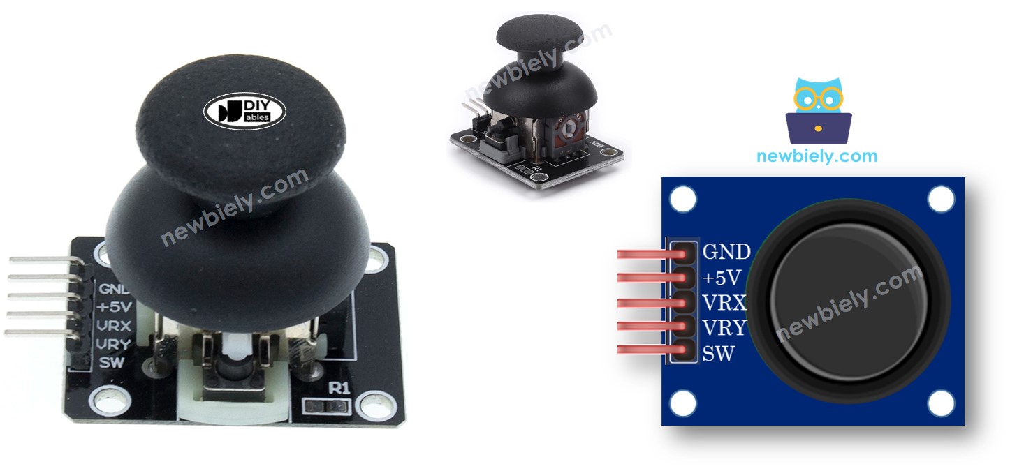
Overview of Joystick Sensor
The analog joystick uses dual potentiometer architecture for two-axis position sensing with integrated pushbutton. Each axis uses a 10kΩ linear potentiometer operating as a voltage divider, producing analog outputs (0V to VCC) proportional to shaft position. A spring-return mechanism centers the stick when released.
Electrical characteristics include 5V supply voltage operation with current consumption under 1mA. The analog outputs swing rail-to-rail across full mechanical travel. The pushbutton features normally-open contacts rated for 12V/50mA switching.
Pinout
The pinout configuration defines the electrical interface between the joystick module and the Arduino Giga R1 WiFi system. Correct wiring is essential for reliable operation — an incorrect connection may damage the component or produce erratic readings due to improper voltage levels or signal contamination.
GND: Ground reference (0V). Connects to Arduino ground plane to establish common electrical reference. This connection carries return current for both analog and digital circuits within the joystick assembly.
VCC: Primary power supply input (5V nominal, 4.5V-5.5V acceptable range). Connects to Arduino 5V output to power internal potentiometer excitation and button pull-up circuits. Current draw remains constant at approximately 0.8mA during operation.
VRX: X-axis analog output (0V-5V range). Connects to Arduino analog input pin (A0-A7) to provide horizontal position voltage. Output impedance approximately 2.5kΩ at center position, varying to 10kΩ at mechanical limits.
VRY: Y-axis analog output (0V-5V range). Connects to Arduino analog input pin (A0-A7) to provide vertical position voltage. Electrical characteristics match VRX channel for consistent dual-axis performance.
SW: Pushbutton switch output (normally-open contact). Connects to Arduino digital GPIO pin configured with internal pull-up resistor. Pin reads HIGH (3.3V) when button released, LOW (0V) when pressed. Contact bounce duration typically 1-3ms requiring software debouncing.
The Arduino Giga R1 WiFi's analog inputs feature high impedance (>10MΩ) ensuring minimal loading of the joystick's potentiometer outputs. The platform's 3.3V logic levels are fully compatible with 5V analog signals, providing excellent noise margins. GPIO pins include configurable pull-up resistors (20kΩ-50kΩ) suitable for direct pushbutton interfacing without external components.
Common wiring errors include reversed power connections (which may damage internal circuits), shared analog pins causing crosstalk, and missing pull-up configuration on the switch pin resulting in floating logic states. Verify connections with a multimeter before applying power to prevent component damage.
How It Works
The joystick operates through dual-axis resistive position sensing combined with mechanical switching for comprehensive user input capture. Understanding the underlying electrical and mechanical principles enables optimal integration and troubleshooting.
Horizontal Axis Operation (VRX): When the joystick moves left or right, the X-axis potentiometer's wiper travels along its resistive element. At the left mechanical limit, the wiper connects near the ground terminal, producing approximately 0V output. At the right limit, the wiper approaches the VCC terminal, generating close to 5V output. The Arduino Giga R1 WiFi's ADC converts these voltages to digital values: 0 (left extreme) to 1023 (right extreme) in 10-bit mode, or 0 to 4095 in 12-bit mode. Center position typically reads 511 (10-bit) or 2047 (12-bit), though mechanical tolerances may cause slight variations requiring calibration.
Vertical Axis Operation (VRY): The Y-axis follows identical principles with perpendicular mechanical orientation. Upward joystick motion typically decreases the VRY voltage toward 0V, while downward motion increases it toward 5V. However, axis polarity depends on mechanical assembly orientation and may vary between manufacturers. Initial testing determines the actual direction mapping for each specific joystick module.
Simultaneous Dual-Axis Operation: When moved diagonally, both potentiometers change simultaneously, creating coordinate pairs representing precise 2D positions. The Arduino Giga R1 WiFi can sample both channels nearly instantaneously (ADC conversion time <1µs), providing real-time position tracking. Mathematical conversion transforms these coordinates into polar form (angle and magnitude) or discrete directional commands as application requirements dictate.
Pushbutton Operation: The integrated tactile switch activates when vertical force depresses the joystick stem. The normally-open contacts close, connecting the SW pin to the internal ground reference. With the Arduino GPIO configured for internal pull-up, the SW pin reads HIGH during normal operation and LOW when pressed. Contact bounce typically lasts 1-3 milliseconds, requiring software debouncing techniques or hardware RC filtering for reliable edge detection.
Spring Return Mechanism: Internal springs center the joystick when released, ensuring consistent reference positioning. The centering force increases linearly with displacement, providing tactile feedback to the operator. This mechanical design enables proportional control applications where displacement magnitude indicates desired response intensity.
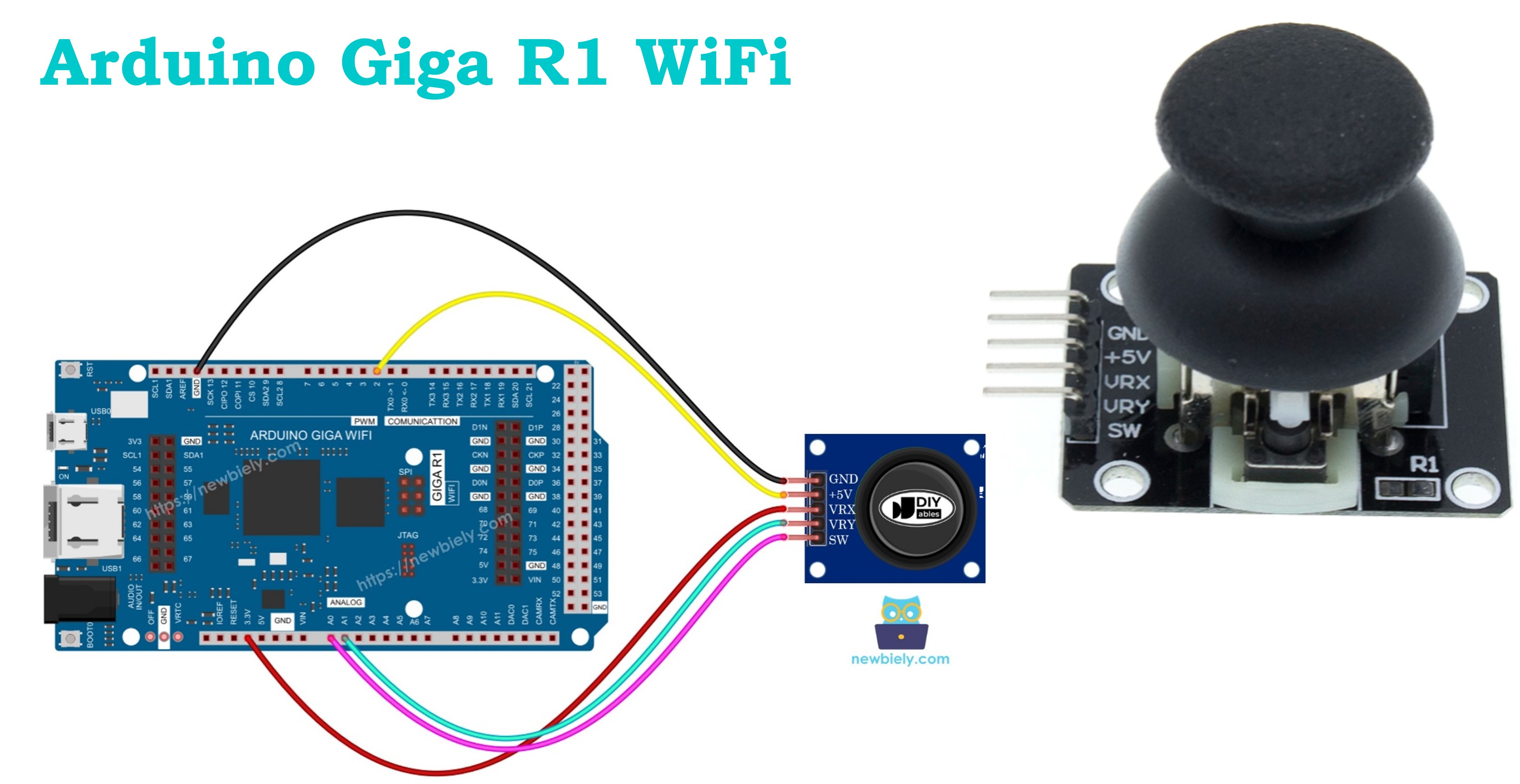
Wiring Diagram
The wiring implementation establishes electrical connections between the joystick module and Arduino Giga R1 WiFi for reliable analog signal transmission and digital control. The diagram demonstrates the minimum viable connection scheme for full joystick functionality.
Electrical Note: The diagram above shows the minimum viable connection for development and prototyping. For production applications or extended operation, consider adding 100nF ceramic capacitors between each analog line and ground near the Arduino inputs to reduce high-frequency noise. For industrial environments, implement RC low-pass filters (1kΩ + 10nF) on analog inputs to eliminate switching noise from nearby equipment.
Power supply considerations include ensuring adequate current capability from the Arduino's 5V regulator. While the joystick draws minimal current (<1mA), simultaneous operation of multiple peripherals may approach the regulator's limits. For battery-powered applications, the joystick's continuous power draw should be factored into overall power budgets, though its static consumption remains negligible compared to active components like WiFi radios or servo motors.
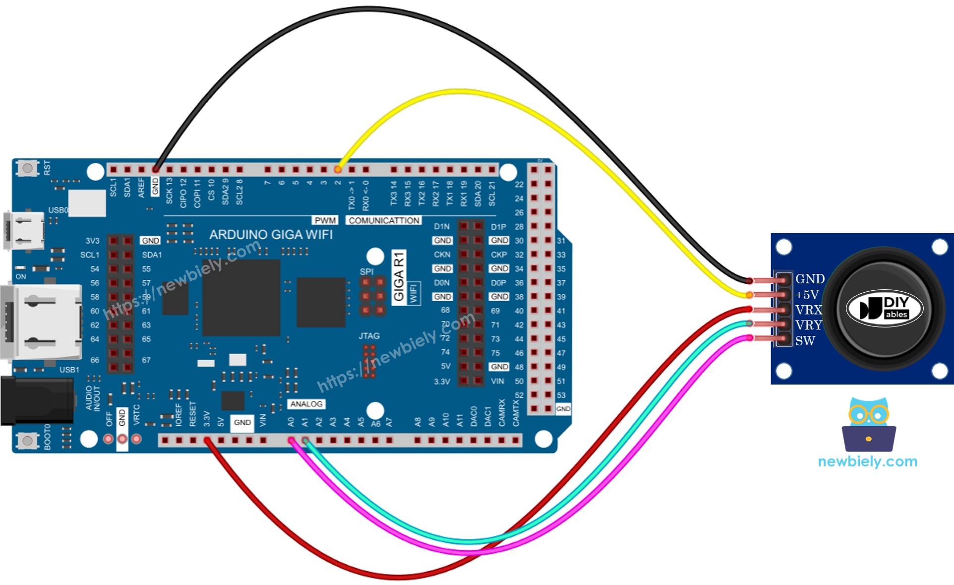
This image is created using Fritzing. Click to enlarge image
| Joystick Pin | Arduino Giga R1 WiFi Pin | Signal Type |
|---|---|---|
| GND | GND | Power Ground |
| VCC | 5V | Power Supply (+5V) |
| VRX | A1 | X-Axis Analog Output |
| VRY | A0 | Y-Axis Analog Output |
| SW | Pin 2 | Digital Switch Output |
How To Program For Joystick
The joystick interface requires coordinated analog and digital input handling to capture complete user interaction data. The implementation approach balances real-time responsiveness with signal conditioning for robust operation in varied environmental conditions.
Analog Input Processing: The dual-axis analog interface utilizes the Arduino Giga R1 WiFi's high-resolution ADC channels to capture position data. The analogRead() function samples each axis independently, returning values from 0 to 1023 in standard 10-bit mode. The platform's 12-bit ADC capability can be accessed through advanced configuration for applications requiring higher precision positioning.
Digital Button Interface: The pushbutton component functions as a standard momentary switch requiring debouncing for reliable operation. The recommended approach employs the ezButton library which provides professional-grade debouncing algorithms and internal pull-up resistor management. This library eliminates the complexity of manual debouncing while ensuring consistent button state detection across varying environmental conditions.
Signal Conditioning Considerations: Raw analog values benefit from filtering and calibration processing to compensate for manufacturing tolerances and electrical noise. The Arduino Giga R1 WiFi's computational capabilities support real-time digital filtering techniques including moving averages, median filters, and Kalman filtering for applications requiring stable position data. Center position calibration accounts for mechanical variations between joystick modules.
Timing and Sampling Strategy: The dual-core architecture enables dedicated input processing threads for time-critical applications. Typical polling rates of 100-1000Hz provide smooth response for human interface applications, while specialized control systems may require higher rates utilizing interrupt-driven sampling or DMA transfer modes.
After acquiring raw position values, most applications require conversion to application-specific coordinate systems, directional commands, or servo angles. The following code examples demonstrate these transformation techniques with practical implementation details for common use cases.
Arduino Code
This section provides comprehensive Arduino code examples demonstrating progressive joystick functionality implementation. Each example builds upon previous concepts while introducing advanced techniques for professional joystick interface development. The code examples are structured for clarity and include inline documentation explaining design decisions and configuration options.
The implementation approach emphasizes modularity and reliability, incorporating proper signal conditioning, error handling, and scalable architecture suitable for integration into larger systems. Key sections demonstrate analog-to-digital conversion, button state management, coordinate transformation, and real-time control applications.
Example code structure: Basic analog reading establishes the foundation, followed by integrated button handling using professional debouncing techniques. Advanced examples demonstrate practical coordinate transformation for directional control and servo motor positioning. Each example includes comprehensive error checking and calibration procedures appropriate for production implementations.
Library dependencies: The button handling examples utilize the ezButton library for robust switch debouncing and state management. This library abstracts the complexity of reliable button interfaces while providing consistent API for integration with larger control systems. Installation and configuration instructions ensure proper library setup for immediate code execution.
Reads analog values from joystick
Detailed Instructions
For initial Arduino Giga R1 WiFi setup, refer to the Arduino Giga R1 WiFi Getting Started guide before proceeding.
- Connect Hardware: Wire the joystick to the Arduino according to the wiring diagram above. Verify all connections with a multimeter before applying power to prevent component damage.
- Load Code: Copy the provided code into the Arduino IDE. The sketch initializes serial communication and configures analog input pins for joystick reading.
- Upload Program: Click the Upload button in Arduino IDE to compile and transfer the code to the Arduino Giga R1 WiFi. Monitor the compilation output for any library dependency warnings.
- Open Serial Monitor: Launch the Serial Monitor (Tools → Serial Monitor) and set the baud rate to 9600. You should immediately see coordinate values displaying at regular intervals.
- Calibrate Range: Push the joystick to its maximum limits in all four directions while observing the Serial Monitor. Note the minimum and maximum values for both X and Y axes — these define the usable range for your specific joystick module.
- Test Center Position: Release the joystick and observe the center position values. Typical readings should be approximately 512±20 for both axes in 10-bit mode, though mechanical tolerances may cause variations.
- Verify Operation: Rotate the joystick in a complete circle while monitoring the output. Both axes should vary smoothly without sudden jumps or dead zones, indicating proper electrical connections and mechanical operation.
Technical Note: The analogRead() function performs a single ADC conversion taking approximately 100µs. For applications requiring higher sampling rates or noise reduction, consider implementing hardware timer-triggered conversions with averaging filters or utilizing the Arduino Giga R1 WiFi's DMA capabilities for continuous background sampling.
Reads analog values and reads the button state from a joystick
Detailed Instructions
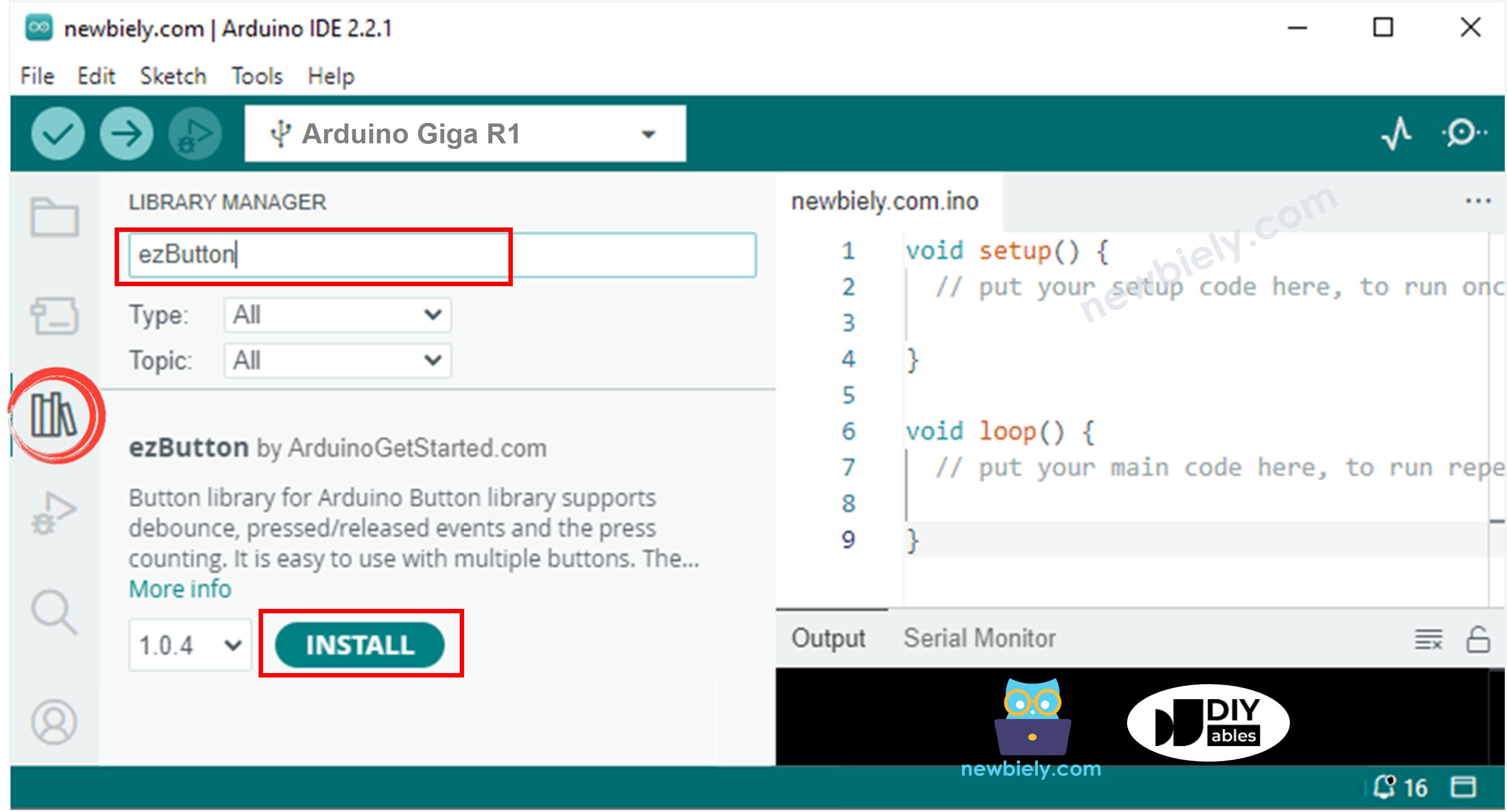
- Install Library: Navigate to the Libraries icon on the left bar of the Arduino IDE. Search for "ezButton" and locate the library by ArduinoGetStarted.com. Click Install to add professional button handling capabilities to your development environment.
- Verify Wiring: Ensure the SW pin is connected to digital pin 2 on the Arduino Giga R1 WiFi. The ezButton library will automatically configure the internal pull-up resistor, eliminating the need for external components.
- Upload Code: Copy the enhanced code into Arduino IDE and upload to the board. The sketch now includes both analog coordinate reading and debounced button state detection.
- Test Analog Function: Move the joystick in all directions to verify continuous coordinate tracking. The analog values should update smoothly without affecting button detection functionality.
- Test Button Function: Press the joystick stem firmly while observing the Serial Monitor. The button state should change reliably without false triggers from mechanical vibration or electrical noise.
- Verify Integration: Simultaneously move the joystick and press the button to confirm both analog and digital functions operate independently without mutual interference.
- Check Debouncing: Rapidly press and release the button multiple times. The ezButton library should provide clean state transitions without bounce-related false triggering common in manual implementations.
Technical Note: The ezButton library implements a configurable debounce delay (default 50ms) suitable for most mechanical switches. For applications requiring faster response times, the debounce period can be reduced to 10-20ms, though this may increase sensitivity to electrical noise in industrial environments.
Converts analog value to MOVE LEFT/RIGHT/UP/DOWN commands
Detailed Instructions
- Configure Thresholds: The code includes predefined threshold values that determine directional sensitivity. The default settings provide reliable operation while avoiding false triggers from minor joystick movements or electrical noise.
- Upload and Test: Load the command conversion code to the Arduino and open the Serial Monitor. Move the joystick deliberately in each cardinal direction to verify proper command generation.
- Calibrate Sensitivity: Adjust the threshold values in the code if needed. Lower values increase sensitivity but may cause unwanted triggering from vibration or electrical interference. Higher values require more deliberate joystick movement but improve stability.
- Test Diagonal Movement: Push the joystick diagonally to confirm simultaneous command detection. The system should correctly identify combinations like "UP + RIGHT" for diagonal control applications.
- Verify Deadband: Return the joystick to center position and confirm no commands are generated. The deadband zone prevents continuous triggering when the joystick is nominally centered but experiencing minor variations.
- Monitor Command Timing: Observe how quickly commands change as you move the joystick. The system should respond immediately to position changes while maintaining stable output during steady-state conditions.
Technical Note: The threshold-based approach provides discrete directional commands suitable for digital control applications like motor direction, menu navigation, or game controls. For applications requiring proportional control, consider implementing scaled output values proportional to joystick displacement magnitude rather than binary command states.
※ NOTE THAT:
At any time, the system may generate no commands (center position), one command (cardinal direction), or two commands simultaneously (diagonal movement such as UP and LEFT). This behavior enables comprehensive directional control for applications requiring diagonal movement capabilities.
Converts analog values to angles to control two servo motors
The detailed implementation for servo motor control applications is presented in the Arduino - Joystick controls Servo Motor tutorial, which covers advanced coordinate transformation techniques, servo positioning algorithms, and real-time pan-tilt control systems suitable for robotic applications and camera positioning mechanisms.
Application Ideas
Industrial Machine Control: Implement joystick control for CNC machine manual positioning, crane operation interfaces, or material handling equipment. The Arduino Giga R1 WiFi's dual-core architecture enables real-time control loops while maintaining safety monitoring and communication functions. Integration with industrial protocols like Modbus or CANbus allows seamless connection to existing automation systems with deterministic response times.
Robotic Pan-Tilt Camera System: Create professional camera positioning systems for security monitoring, broadcasting, or research applications. The joystick's analog precision combined with the Arduino's servo control capabilities delivers smooth, proportional movement control. WiFi connectivity enables remote operation and integration with IP camera systems for comprehensive surveillance solutions.
Remote Control Vehicle Interface: Develop advanced RC vehicle control systems with proportional steering and throttle control. The Arduino Giga R1 WiFi's processing power supports sophisticated control algorithms including acceleration limiting, steering compensation, and telemetry data overlay. Wireless communication enables long-range operation with real-time status feedback and emergency stop capabilities.
Gaming Controller Development: Build custom gaming controllers for specialized applications like flight simulators, racing games, or accessibility interfaces. The platform's USB host capability allows direct PC interface, while the dual-core design supports complex input processing, force feedback control, and customizable response curves for enhanced user experience.
Laboratory Instrumentation Control: Design precision positioning interfaces for scientific equipment, microscope stages, or optical alignment systems. The high-resolution ADC and floating-point processing capabilities enable sub-degree positioning accuracy with real-time coordinate transformation and motion smoothing algorithms suitable for research-grade instrumentation.
Home Automation Interface: Create centralized control panels for smart home systems with intuitive joystick navigation through device menus and settings. The WiFi connectivity integrates with IoT platforms like Home Assistant or custom MQTT implementations, while the touchscreen-ready interface supports comprehensive home automation control with visual feedback and status monitoring.
Video Section
The accompanying demonstration video shows complete hardware assembly procedures, live code execution, and real-time serial monitor output. The video covers proper wiring techniques to prevent common connection errors, demonstrates calibration procedures for optimal joystick response, and shows practical examples of coordinate transformation for control applications. Watch for the expected serial output patterns and button response timing that indicate correct implementation.
Challenge Yourself
Challenge: Implement adaptive sensitivity control that adjusts joystick response based on movement speed. Add exponential response curves for fine control near center position and linear response at extremes, similar to professional RC transmitter implementations.
Challenge: Create a data logging system that records joystick usage patterns to SD card storage. Log timestamps, coordinates, and button events with configurable sampling rates, then implement playback functionality for automated testing or user behavior analysis.
Challenge: Develop a WiFi-based remote joystick interface that transmits control data to another Arduino Giga R1 WiFi over TCP/UDP protocols. Include bidirectional communication for telemetry feedback, connection status monitoring, and emergency stop capabilities with sub-100ms latency requirements.
Challenge: Build a multi-joystick input multiplexer supporting 4-8 joystick modules with automatic detection and calibration. Utilize the Arduino's multiple ADC channels and implement individual deadband adjustment, coordinate scaling, and conflict resolution for multi-operator control systems.
Challenge: Integrate machine learning algorithms for gesture recognition based on joystick movement patterns. Implement neural network inference using the dual-core architecture to recognize complex motion sequences for advanced control interfaces or accessibility applications requiring pattern-based command input.