Arduino Giga R1 WiFi LED Blink
This tutorial demonstrates how to control LEDs with the Arduino Giga R1 WiFi using digital output pins. By the end, you will have both the built-in LED and an external LED blinking at controlled intervals. What's covered:
- Wiring an external LED to the Arduino Giga R1 WiFi with proper current limiting
- Programming digital pins for LED control using digitalWrite()
- Understanding LED electrical characteristics and safe operating parameters
Hardware Preparation
Or you can buy the following kits:
| 1 | × | DIYables Sensor Kit (18 sensors/displays) |
Additionally, some of these links are for products from our own brand, DIYables .
Buy Note: Use the LED Module for easier wiring. It includes an integrated resistor.
Overview of LED
LED (Light Emitting Diode) is a semiconductor device designed for visual indication and illumination applications. Standard 5mm LEDs typically operate at 1.8-3.3V forward voltage with 10-20mA forward current, depending on the specific diode material and color. The device functions through electroluminescence - when forward-biased, electrons recombine with holes at the P-N junction, releasing photons at a wavelength determined by the semiconductor bandgap energy.
LEDs require current limiting for safe operation, as they exhibit exponential current-voltage characteristics. Without proper current limiting, the device will draw excessive current and fail. The Arduino Giga R1 WiFi's GPIO pins can source up to 20mA at 3.3V logic levels, making them suitable for direct LED control when properly current-limited with series resistors.
Compared to incandescent indicators, LEDs offer superior efficiency (80-90% electrical-to-optical conversion), longer operational life (25,000-100,000 hours), and faster switching response (<100ns). They integrate seamlessly with the Arduino Giga R1 WiFi's dual-core STM32H747XI architecture, which provides abundant GPIO resources across multiple ports with independent drive capability.
Pinout
The pinout configuration determines the electrical connection requirements for reliable LED operation. Correct polarity is critical - reverse bias beyond the reverse breakdown voltage (typically 5-6V) will permanently damage the LED junction.
LED includes two pins:
- Cathode(-) pin: Ground reference connection (0V). Connects to Arduino GND or negative supply rail. This terminal must be held at lower potential than the anode for forward conduction.
- Anode(+) pin: Positive terminal for current injection. Connects to Arduino GPIO pin through current-limiting resistor. Forward current flows from this terminal to cathode when forward-biased above threshold voltage.
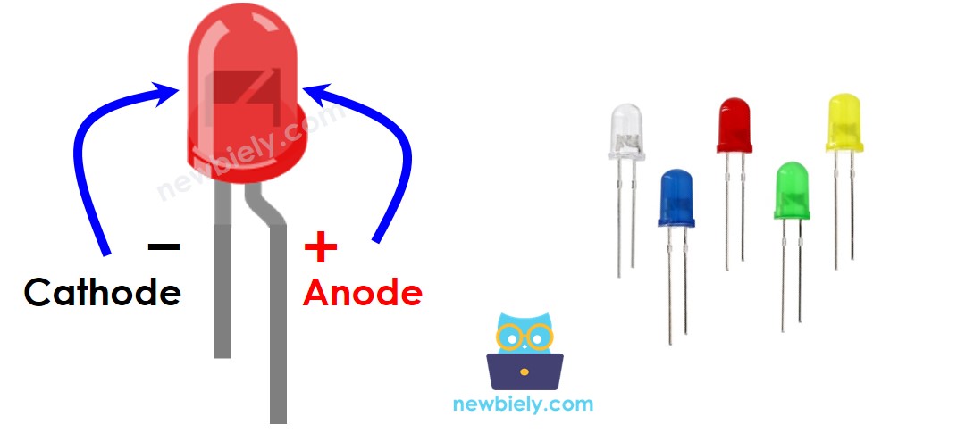
Physical identification: The cathode typically connects to the shorter lead and flat edge of the LED case. The anode connects to the longer lead. Internal examination shows the cathode connects to the larger die flag, while the anode connects to the smaller wire bond post.
Signal requirements: Logic HIGH (3.3V) on the Arduino Giga R1 WiFi GPIO pin forward-biases the LED through the series resistor. Logic LOW (0V) reverse-biases the junction, blocking current flow. Pull-up resistors are not required for this application.
How It Works
LED operation relies on forward-bias conduction through the P-N semiconductor junction. The Arduino Giga R1 WiFi's GPIO pins can be programmatically configured to output either 0V (GND) or 3.3V (VCC) logic levels.
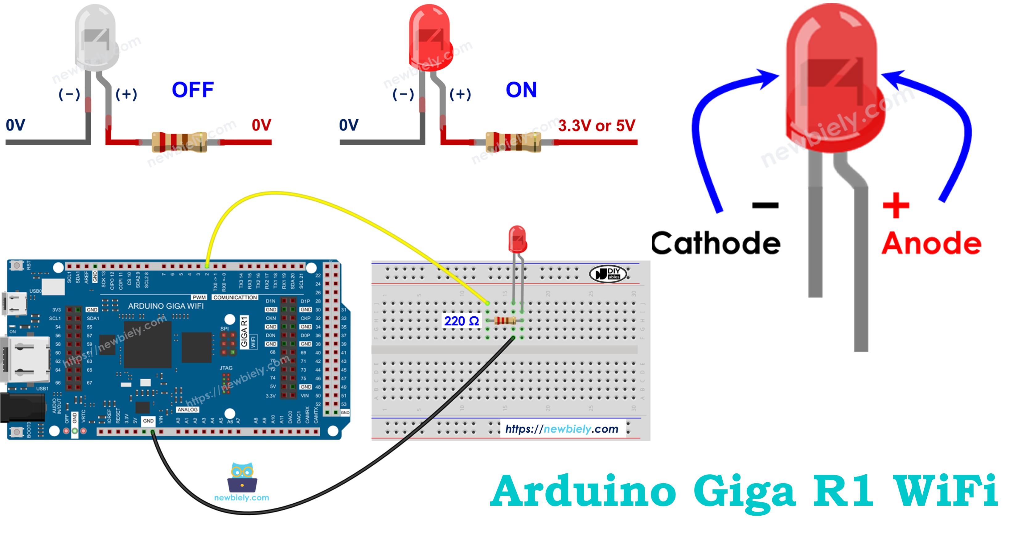
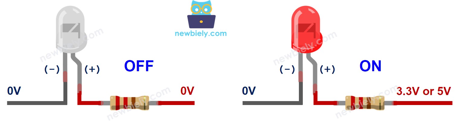
After connecting the cathode(-) to GND:
- If connecting GND to the anode(+): No potential difference exists across the junction. LED remains OFF with zero forward current.
- If connecting VCC to the anode(+): Forward voltage drop (typically 1.8-2.2V for red LEDs) allows current flow determined by: I = (Vsupply - Vforward) / Rseries. LED illuminates proportionally to forward current.
The current-limiting resistor value calculation: For 3.3V supply, 2.0V LED drop, and 15mA target current: R = (3.3V - 2.0V) / 0.015A = 87Ω minimum. A 220Ω resistor provides conservative current limiting at approximately 6mA, ensuring reliable operation within the Arduino Giga R1 WiFi's current sourcing capability.
PWM (Pulse Width Modulation) control enables brightness regulation by varying the duty cycle of the GPIO output. The Arduino Giga R1 WiFi's advanced timers support up to 16-bit PWM resolution, providing smooth brightness control with minimal visible flicker above 200Hz switching frequency.
※ NOTE THAT:
- For most of LED, we need to use a resistor. The resistor can be placed between the anode(+) and VCC or between the cathode(-) and GND. The value of the resistor depends on the specification of the LED.
- Some kinds of LEDs have a built-in resistor. We may not need to use a resistor for those kinds of LEDs.
Arduino - LED
When an Arduino Giga R1 WiFi pin is configured as a digital output using pinMode(pin, OUTPUT), the pin's voltage can be programmatically controlled between GND (0V) and VCC (3.3V). The STM32H747XI microcontroller provides push-pull output drivers capable of sourcing or sinking up to 20mA per pin, with total package current limitations of 120mA for all pins combined.
By connecting the Arduino Giga R1 WiFi's GPIO pin to the LED's anode(+) through a current-limiting resistor, we can programmatically control the LED's illumination state. The digitalWrite() function directly controls the output driver state, with digitalWrite(pin, HIGH) enabling the upper P-channel MOSFET and digitalWrite(pin, LOW) enabling the lower N-channel MOSFET in the output stage.
GPIO electrical characteristics specific to the Arduino Giga R1 WiFi include 5V tolerance on most pins, enabling direct interface with 5V logic systems while maintaining 3.3V output levels. This compatibility extends the LED control capability to various voltage domains common in embedded systems integration.
Wiring Diagram
This implementation demonstrates fundamental digital output control using the Arduino Giga R1 WiFi's GPIO capabilities. The circuit design follows standard current-limiting practices to ensure safe LED operation within the microcontroller's electrical specifications.
We are going to run through two examples:
- Example code controls the built-in LED on Arduino Giga R1 WiFi.
- Modifying Arduino Code controls the external LED.
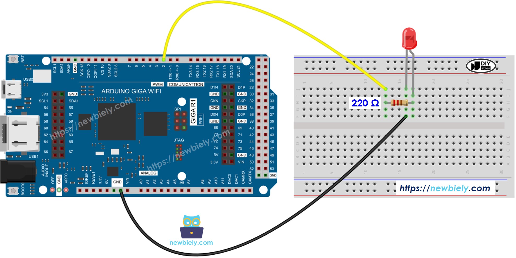
This image is created using Fritzing. Click to enlarge image
Electrical Note: The diagram above shows the minimum viable connection. For production or extended use, consider adding a 100nF ceramic bypass capacitor near the LED circuit to suppress switching noise, and verify that total GPIO current consumption remains within the STM32H747XI's 120mA aggregate limit when controlling multiple LEDs simultaneously.
Power supply considerations: The external LED circuit draws approximately 6mA when active, well within the Arduino Giga R1 WiFi's current sourcing capability. Total power dissipation in the current-limiting resistor is P = I²R = (0.006A)² × 220Ω = 8mW, requiring no special thermal management.
| LED Pin | Arduino Giga R1 WiFi Pin |
|---|---|
| Anode (+) | Digital Pin 9 (through 220Ω resistor) |
| Cathode (-) | GND |
How To Program
The following implementation demonstrates basic digital GPIO control for LED switching applications. The code structure utilizes Arduino's standard digital I/O functions to configure pin modes and control output states. Key aspects include pin initialization during setup() and state control within the main execution loop.
The digitalWrite() function directly interfaces with the STM32H747XI's GPIO registers, providing deterministic timing for LED control applications. Response time from function call to pin state change is typically 2-3 CPU cycles, enabling precise timing control suitable for high-frequency blinking patterns.
- Configure an Arduino Giga R1 WiFi pin to digital output mode using pinMode() function. This configures the GPIO port direction register and enables the output driver. For example, pin 9:
- Program the pin to GND (0V) to turn OFF LED using digitalWrite() function. This enables the N-channel output driver and disables current flow through the LED:
- Program the pin to VCC (3.3V) to turn ON LED using digitalWrite() function. This enables the P-channel output driver and allows forward current through the LED circuit:
Arduino Code
Detailed Instructions
For initial Arduino Giga R1 WiFi setup, refer to the Arduino Giga R1 WiFi Getting Started guide before proceeding.
- Connect: Attach Arduino Giga R1 WiFi to PC via USB Type-C cable. Verify connection through Device Manager or System Information showing the board's virtual COM port assignment.
- Configure: Open Arduino IDE and select "Arduino Giga R1 WiFi" from Tools → Board menu. Set the correct COM port under Tools → Port. Confirm board communication by checking the status bar for successful connection.
- Upload: Copy the blink code and paste into a new Arduino IDE sketch. Click the Upload button (right arrow icon) to compile and transfer the program to the Arduino Giga R1 WiFi's flash memory.
- Verify: Observe the built-in LED (connected to LED_BUILTIN pin) toggling between ON and OFF states at 1-second intervals. Serial monitor is not required for this basic functionality verification.
- Troubleshoot: If the LED does not blink, verify the board selection matches your hardware, check USB cable integrity, and confirm the code compiled without errors. Common issues include incorrect board type or communication port conflicts.
Technical Note: The built-in LED on the Arduino Giga R1 WiFi connects internally through appropriate current limiting, eliminating the need for external resistors. The LED_BUILTIN constant automatically maps to the correct GPIO pin for the target board variant.
Code Explanation
Read the line-by-line explanation in comment lines of code!
※ NOTE THAT:
The above code uses the delay(). This function blocks Arduino from doing other tasks during the delay time. If your project requires to do some tasks, avoid blocking Arduino by using the non-blocking method for Arduino.
Modifying Arduino Code
This enhanced implementation extends LED control to external hardware components connected via breadboard. The modification demonstrates GPIO pin flexibility and timing parameter adjustment for different visual effects.
Detailed Instructions
- Wire: Connect external LED to Arduino Giga R1 WiFi following the wiring diagram above. Ensure correct polarity - anode (longer lead) connects to digital pin 9 through 220Ω resistor, cathode (shorter lead) connects directly to GND.
- Modify: Update the code constants to target the external LED circuit. Change LED_BUILTIN to pin 9 for external GPIO control. Reduce delay from 1000ms to 500ms for faster blinking frequency.
- Test: Upload the modified code and verify external LED operation. The LED should blink at 1Hz frequency (500ms ON, 500ms OFF). Built-in LED will remain static since it's no longer controlled by the program.
- Validate: Measure pin 9 voltage with multimeter during operation - should alternate between 0V (LED OFF) and 3.3V (LED ON). Current consumption through the 220Ω resistor should be approximately 6mA during ON state.
Technical Note: External LED circuits provide greater flexibility for brightness control, color selection, and current handling compared to built-in indicators. The Arduino Giga R1 WiFi's abundant GPIO resources enable simultaneous control of multiple LED circuits for complex visual indication systems.
※ NOTE THAT:
This tutorial provides in-depth knowledge that helps you understand the working principle. To make it easy, you can use Arduino - LED library.
Challenge Yourself
Challenge 1: Implement a multi-LED sequence controller using pins 8, 9, and 10 with 220Ω current-limiting resistors. Create a rotating pattern where only one LED illuminates at a time, shifting every 200ms. This demonstrates array-based pin control and timing loops.
Challenge 2: Design a PWM-based brightness controller using analogWrite() to fade the LED in and out smoothly. Implement a breathing effect with 10ms delay increments and 0-255 PWM range. This explores the Arduino Giga R1 WiFi's advanced timer capabilities.
Challenge 3: Create a button-controlled LED state machine combining digital input and output. Wire a pushbutton to pin 2 with internal pull-up enabled, and implement toggle functionality where each button press changes the LED state. This integrates interrupt handling with GPIO control.
Challenge 4: Build a serial-controlled LED system that responds to commands sent through the Serial Monitor. Implement commands like "ON", "OFF", "BLINK:500" to control LED state and timing parameters. This demonstrates UART communication integration with hardware control.
Challenge 5: Develop a temperature-responsive LED indicator using the Arduino Giga R1 WiFi's built-in temperature sensor. Configure the LED to blink faster as temperature increases, creating a thermal monitoring system. This leverages the STM32H747XI's integrated analog peripherals.
Additional Knowledge
Question: Which pins on Arduino Giga R1 WiFi can be used as digital output pins to control LEDs?
Answer: The Arduino Giga R1 WiFi provides extensive GPIO capabilities through its STM32H747XI microcontroller:
- Digital pins 0-13: Standard GPIO with 3.3V/5V tolerance
- Analog pins A0-A7: Can be configured as digital outputs using pinMode()
- Additional GPIO pins on extended headers: Pins 14-21 and beyond, depending on board configuration
- PWM-capable pins: 2, 3, 5, 6, 9, 10, 11, 12, 13 support analogWrite() for brightness control
※ NOTE THAT:
At a time, one pin can take only one task. If you already used a pin for another task (e.g, digital input, analog input, PWM, UART...), you should NOT use it as digital output to control LED. For example, if we use Serial.println() function, we should NOT use pin 0 and 1 for any other purpose because these pins are used for Serial.
Extendability
This LED control tutorial demonstrates fundamental principles applicable to controlling any ON/OFF device or machine through the Arduino Giga R1 WiFi's digital outputs. The same digitalWrite() commands can activate solenoids, motors, pumps, heating elements, or industrial automation equipment.
Industrial Automation: The Arduino Giga R1 WiFi's dual-core architecture enables simultaneous LED status indication while processing sensor data or network communication. Real-time control applications benefit from the deterministic GPIO response times and extensive peripheral integration.
IoT Integration: LED status indicators can provide local feedback for network-connected devices. The built-in WiFi capability allows remote LED control through web interfaces or cloud services, creating distributed monitoring systems.
Data Logging Applications: Combine LED control with the Arduino Giga R1 WiFi's USB host capability to log LED states to external storage devices. This creates audit trails for industrial processes or equipment status monitoring.
※ NOTE THAT:
for devices/machines that use a high power supply ( > 5v) and/or high-current consumption, we need to use a relay between output pin and devices/machines - see Arduino - Relay.