Arduino Giga R1 WiFi Multi-Function Shield
The Arduino Giga R1 WiFi is one of the most powerful boards in the Arduino ecosystem — featuring a dual-core STM32H747 processor, built-in Wi-Fi and Bluetooth, and a generous amount of RAM and flash. Despite its advanced capabilities, the Giga R1 WiFi retains the Mega/Uno-compatible header layout, which means the Multi-Function Shield fits right on top.
By following this tutorial, you will be able to:
- Mount the Multi-Function Shield onto the Arduino Giga R1 WiFi.
- Present numeric and alphanumeric data on the 4-digit 7-segment display.
- Capture press and release events from three tactile buttons.
- Manage four LEDs — turn them on, turn them off, toggle, or set up blink patterns.
- Produce timed beeps using the onboard buzzer.
- Sample the potentiometer for raw analog values or percentage readings.
- Obtain Celsius temperature from the LM35 analog sensor.
Hardware Preparation
Or you can buy the following kits:
| 1 | × | DIYables Sensor Kit (18 sensors/displays) |
Additionally, some of these links are for products from our own brand, DIYables .
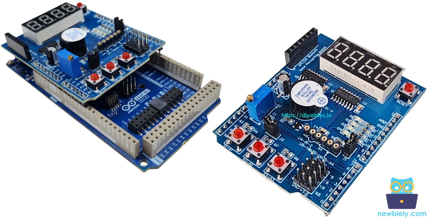
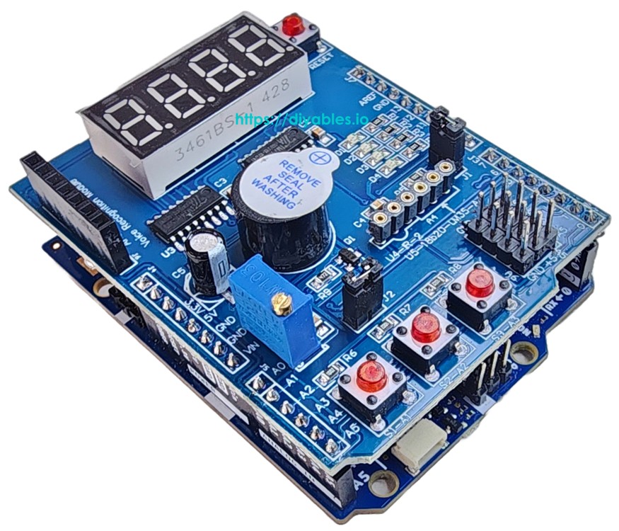
Overview of Multi-Function Shield
The Multi-Function Shield consolidates several frequently used peripherals into a single stackable board. Once placed on the Giga R1 WiFi, you get instant access to all of the following without wiring a single jumper:
- 4-Digit 7-Segment Display — Shift-register driven (74HC595). Renders numbers, floating-point values, A–Z text, and symbols like the degree character (°).
- 3 Push Buttons (S1, S2, S3) — Each is active LOW; internal pullup resistors and software debouncing are managed by the library.
- 4 LEDs (D1–D4) — Active LOW digital outputs supporting on, off, toggle, and configurable blink intervals.
- Buzzer — Active LOW. Programmable beep duration with an optional pre-delay.
- Potentiometer — Wired to analog input A0. Provides either a raw ADC value or a percentage.
- LM35 Temperature Sensor — Wired to analog input A4. Reports temperature in degrees Celsius. The jumper J1 must be removed before using this sensor.
The shield occupies these pins on the Giga R1 WiFi (matching the standard Uno/Mega layout):
| Function | Pin | Function | Pin |
|---|---|---|---|
| LED D1 | 13 | Button S1 | A1 |
| LED D2 | 12 | Button S2 | A2 |
| LED D3 | 11 | Button S3 | A3 |
| LED D4 | 10 | Potentiometer | A0 |
| Buzzer | 3 | LM35 Temp Sensor | A4 |
| Display LATCH | 4 | ||
| Display CLOCK | 7 | ||
| Display DATA | 8 |
Wiring Diagram
The Giga R1 WiFi's Uno-compatible headers accept the Multi-Function Shield directly. Line up the pins carefully and press down — no soldering and no breadboard required.
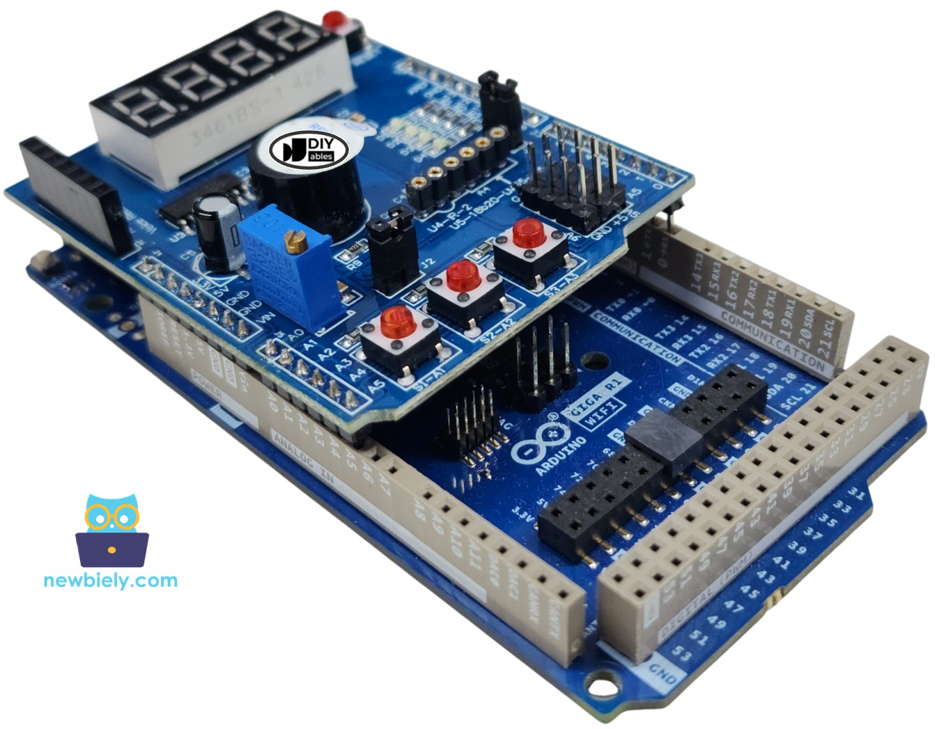
This image is created using Fritzing. Click to enlarge image
Setting Up the Library
- Connect the Giga R1 WiFi to your computer through the USB Type-C port.
- Launch the Arduino IDE, then select Arduino Giga R1 WiFi from the board menu and pick the appropriate port.
- Open the Libraries panel.
- Enter "DIYables_MultiFuncShield" in the search field. The library from DIYables should appear.
- Click Install.
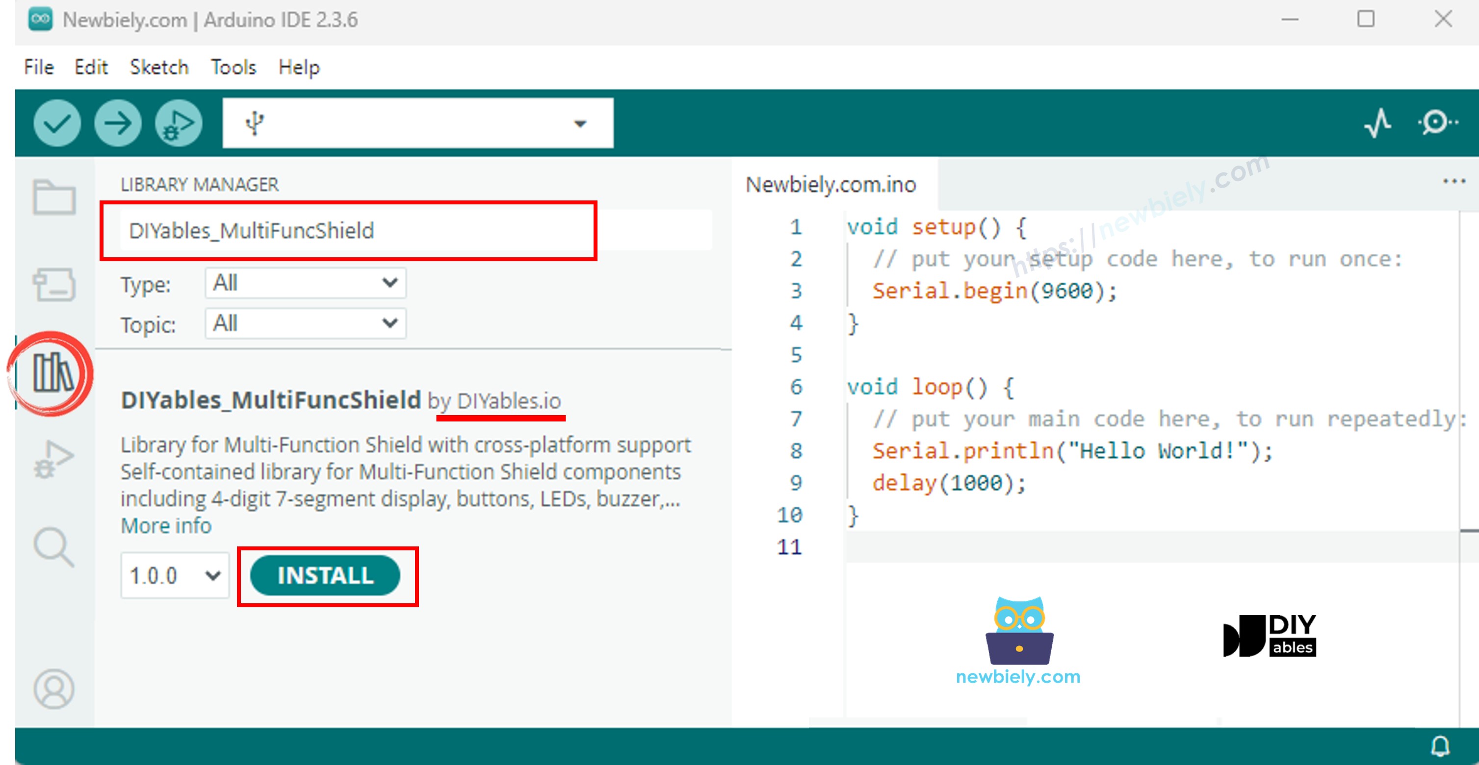
Everything is included in the library package — there are no extra dependencies to install.
Program Template
The following template is the starting point for every Multi-Function Shield sketch:
MFS.begin() initializes the hardware once. MFS.loop() must execute repeatedly to keep the display refreshed, the buttons polled, the LED blink engine ticking, and the buzzer scheduler running.
Driving the 7-Segment Display
The code below puts the display through its paces — integers, leading zeros, decimal numbers, text, dotted text, the degree symbol, and dashes.
Getting Started
- Seat the Multi-Function Shield onto the Giga R1 WiFi.
- Plug in the USB Type-C cable.
- In Arduino IDE, confirm the board and port settings.
- Copy the code above into the editor.
- Tap Upload.
Seven presentation modes cycle at 3-second intervals, demonstrating each display capability.
Display — Quick Reference
| Method | Description | Example | ||
|---|---|---|---|---|
| print(int) | Integer output | MFS.display.print(42) | ||
| print(int, true) | Zero-padded integer | MFS.display.print(42, true) → 0042 | ||
| print(float, dp) | Decimal number with dp fractional digits | MFS.display.print(3.14, 2) | ||
| print(text) | String output (A-Z, 0-9, -, _) | MFS.display.print("HELP") | ||
| setNumber(pos, val) | Assign a digit to position 1–4 | MFS.display.setNumber(1, 5) | ||
| setChar(pos, ch) | Assign a character to a position | MFS.display.setChar(2, 'A') | ||
| setChar(pos, SegChars) | Assign a predefined symbol | MFS.display.setChar(3, SegChars | DEGREE) | |
| setDot(pos) | Enable the dot at a position | MFS.display.setDot(2) | ||
| clear() | Reset all segments | MFS.display.clear() | ||
| show() | Flush pending changes to hardware | MFS.display.show() |
All print() variants invoke show() automatically. For fine-grained composition: clear() → set digits/chars/dots → show().
Predefined symbols in SegChars: DASH, UNDERSCORE, C, E, F, DEGREE.
Controlling the LEDs
Sequentially illuminate each LED, then engage a synchronized blink across all four.
Getting Started
- Upload the sketch.
D1 through D4 activate in order, half a second apart, then all four blink together.
LEDs — Quick Reference
| Method | Description |
|---|---|
| turnON() | Activate the LED |
| turnOFF() | Deactivate the LED |
| toggle() | Invert the current state |
| blink(interval) | Symmetric blinking |
| blink(onTime, offTime) | Asymmetric blinking |
| isOn() | True when the LED is active |
Batch operations on MFS:
| Method | Description |
|---|---|
| allLedsOn() | Activate all four LEDs |
| allLedsOff() | Deactivate all four LEDs |
| allLedsBlink(interval) | Blink all symmetrically |
| allLedsBlink(onTime, offTime) | Blink all asymmetrically |
The LEDs are wired active LOW. Refer to them as MFS.led1–MFS.led4 or MFS.led(1)–MFS.led(4).
Using the Buzzer
Emit a periodic beep.
Getting Started
- Upload the sketch.
A short beep plays every 2 seconds.
Buzzer — Quick Reference
| Method | Description |
|---|---|
| beep(ms) | Buzz for the specified number of milliseconds |
| beep(ms, delayMs) | Pause for delayMs, then buzz for ms |
| stop() | Silence the buzzer instantly |
| isBeeping() | True during an active beep |
Reading the Potentiometer
Read the potentiometer and print the value and percentage to Serial.
Getting Started
- Upload the sketch and open the Serial Monitor.
- Turn the knob and observe the percentage change in real time.
Potentiometer — Quick Reference
| Method | Return Type | Description |
|---|---|---|
| readPot() | int | Unscaled ADC value (0–1023 on Giga R1 WiFi) |
| readPotPercent() | float | Percentage from 0.0 to 100.0 |
Measuring Temperature (LM35)
Display the LM35's Celsius output on the 7-segment display and print it to Serial.
Prerequisite: Remove jumper J1 on the shield. Pin A4 is shared with the I2C SDA signal, and J1 routes it to I2C by default.
Getting Started
- Remove jumper J1.
- Upload the sketch and open the Serial Monitor.
- The temperature updates continuously on the display and in the Serial output.
Readings are passed through a 4-sample moving average filter. The buffer is pre-loaded on the first sample to prevent an inaccurate cold-start value.
Platform Support
The library supports all Arduino platforms (architectures=*).