Arduino Giga R1 WiFi Light Sensor
This guide covers light sensor integration with the Arduino Giga R1 WiFi — from hardware setup to complete ambient light monitoring applications. The photoresistor (also called a light-dependent resistor or LDR) provides analog light level detection through variable resistance characteristics, making it ideal for automatic lighting control, security systems, and environmental monitoring projects.
The Arduino Giga R1 WiFi's advanced analog-to-digital conversion capabilities and dual-core architecture make it exceptionally well-suited for light sensor applications. With its 12-bit ADC resolution and multiple analog input pins, the board delivers precise light measurements while maintaining capacity for concurrent tasks like WiFi data transmission or additional sensor monitoring. This combination enables sophisticated light-responsive systems that can log data remotely, trigger automated responses, or integrate with IoT platforms.
This tutorial demonstrates complete photoresistor implementation, including proper voltage divider configuration, analog signal conditioning, and threshold-based control logic. You'll build working examples that detect ambient light levels, classify brightness qualitatively, and control external devices based on illumination conditions. The code examples progress from basic light measurement to practical applications like automatic LED control.
Real-world applications span industrial automation (daylight harvesting systems), agricultural monitoring (greenhouse light management), security installations (automatic outdoor lighting), and energy management (smart building controls). The tutorial structure covers component fundamentals, electrical integration, programming implementation, and practical deployment considerations to ensure reliable operation in production environments.
Hardware Preparation
Or you can buy the following kits:
| 1 | × | DIYables Sensor Kit (18 sensors/displays) |
Additionally, some of these links are for products from our own brand, DIYables .
The LDR light sensor is very affordable, but it requires a resistor for wiring, which can make the setup more complex. To simplify the wiring, you can use an LDR light sensor module as an alternative.
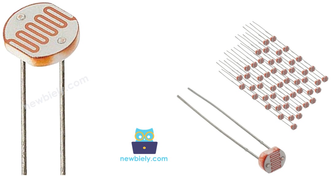
Overview of Light Sensor
The light sensor is a photoresistor device designed for ambient light detection and illuminance measurement. This semiconductor component exhibits variable electrical resistance inversely proportional to incident light intensity, enabling analog light level sensing across a wide dynamic range. Photoresistors typically operate within 0.1 to 100 kΩ resistance range, with dark resistance values reaching 1-10 MΩ depending on the specific CdS (Cadmium Sulfide) composition.
The underlying operating principle relies on the photoconductive effect in semiconductor materials. When photons strike the CdS crystal lattice, they provide sufficient energy to promote electrons from the valence band to the conduction band, increasing the number of free charge carriers. This photogenerated conductivity reduces the material's bulk resistance proportionally to light intensity. The spectral response peaks around 550nm (green light), closely matching human eye sensitivity, making photoresistors ideal for applications requiring daylight-responsive behavior.
Key electrical characteristics include: operating voltage up to 100V DC, maximum power dissipation of 100-200mW, response time of 20-30ms for increasing illuminance (100-200ms for decreasing), and temperature coefficient of approximately -0.5%/°C. The resistance variation typically spans 2-3 orders of magnitude from dark to bright conditions, providing substantial signal swing for reliable measurement.
Integration with the Arduino Giga R1 WiFi requires proper signal conditioning through a voltage divider network. The board's 12-bit ADC (0-4095 counts) provides excellent resolution for light measurement applications. Consider the photoresistor's logarithmic response characteristic when implementing linear brightness scales — software calibration may be necessary for applications requiring linear light level representation.
Compared to photodiodes or phototransistors, photoresistors offer higher sensitivity and lower cost but exhibit slower response times and wider tolerance variations. They excel in applications prioritizing cost-effectiveness over precision timing, such as automatic lighting control, security systems, and general illumination sensing.
Pinout
The photoresistor pinout enables direct integration into voltage divider circuits for Arduino Giga R1 WiFi analog input connection. Correct electrical configuration is essential — improper wiring may result in inverted readings or ADC saturation that compromises measurement accuracy.
PIN 1: Analog signal input, 0-5V range. Connects to Arduino Giga R1 WiFi analog input pin (A0-A5) through voltage divider network. This connection carries the variable voltage signal proportional to light intensity.
PIN 2: Reference connection, typically connected to fixed resistor in voltage divider configuration. Links to either VCC (5V) or GND depending on desired output polarity — connecting to GND through pull-down resistor produces increasing voltage with increasing light.
The two pins are electrically symmetric since the photoresistor functions as a passive resistive element. However, the voltage divider configuration determines signal polarity and measurement range. Standard practice connects one pin to the analog input and voltage divider midpoint, while the other pin connects to either the high-side (VCC) or low-side (GND) of the resistor network.
Signal conditioning requirements include a series resistor (typically 10kΩ) to form the voltage divider and limit current flow. The Arduino Giga R1 WiFi's analog inputs present high impedance (>10MΩ), minimizing loading effects on the measurement circuit. Consider adding a small capacitor (100nF) across the analog input for noise filtering in electrically noisy environments.
Common wiring errors include omitting the voltage divider resistor (resulting in floating input), incorrect analog pin assignment, or power supply connection mistakes. Verify connections with a multimeter — the voltage at the analog input should vary smoothly with light level changes.
How It Works
The photoresistor operates through the photoconductive effect in cadmium sulfide semiconductor material. When incident photons possess energy greater than the material's bandgap (approximately 2.4 eV for CdS), they excite electrons from the valence band into the conduction band, creating electron-hole pairs that increase electrical conductivity. The number of photogenerated charge carriers directly correlates with light intensity, producing the characteristic inverse relationship between illumination and resistance.
In darkness, the photoresistor exhibits maximum resistance (typically 1-10 MΩ) as thermal energy alone generates minimal charge carriers. Under bright illumination, resistance drops to minimum values (100Ω to 1kΩ) due to abundant photogenerated conductivity. This resistance variation spans 3-4 orders of magnitude, providing excellent signal dynamic range for measurement applications.
The spectral response characteristics peak around 550nm wavelength, with sensitivity extending from approximately 400nm (violet) to 700nm (red). This broad-spectrum response makes photoresistors effective for natural daylight sensing but less suitable for applications requiring specific wavelength discrimination. Response time exhibits asymmetry: increasing light produces faster resistance changes (20-30ms) than decreasing light (100-200ms) due to charge carrier recombination dynamics.
Temperature effects influence both dark resistance and photosensitivity. Higher temperatures increase thermal generation of charge carriers, reducing dark resistance and shifting the overall response curve. For precision applications, implement temperature compensation or operate within controlled thermal environments.
WARNING
The light sensor value only reflects the approximated trend of the intensity of light, it does NOT represent the exact luminous flux. Therefore, it should be used only in an application that does NOT require high accuracy.
Arduino - Light Sensor
The Arduino Giga R1 WiFi's analog input architecture enables precise photoresistor interfacing through its advanced ADC subsystem. Analog pins A0 through A5 provide 12-bit resolution (0-4095 counts) with 0-5V input range, delivering superior measurement precision compared to standard 10-bit Arduino implementations. The higher resolution translates to approximately 1.22mV per count, enabling detection of subtle light level variations critical for sophisticated control algorithms.
The voltage divider configuration converts the photoresistor's variable resistance into a measurable voltage signal. By connecting the photoresistor in series with a fixed reference resistor (typically 10kΩ), the midpoint voltage varies according to the resistance ratio. When the photoresistor resistance equals the reference resistor value, the output voltage reaches exactly half the supply voltage (2.5V), providing optimal signal swing utilization.
The analogRead() function performs the analog-to-digital conversion, returning integer values between 0 and 4095 corresponding to the input voltage. Software processing can convert these ADC counts back to voltage values, resistance measurements, or calibrated light intensity units. Consider implementing multi-sample averaging to reduce measurement noise and improve stability in applications requiring high precision.
The Arduino Giga R1 WiFi's dual-core architecture enables concurrent light monitoring alongside other system tasks. Implement light sensing on one core while handling WiFi communication, data logging, or user interface operations on the second core for optimal system performance in complex applications.
Wiring Diagram
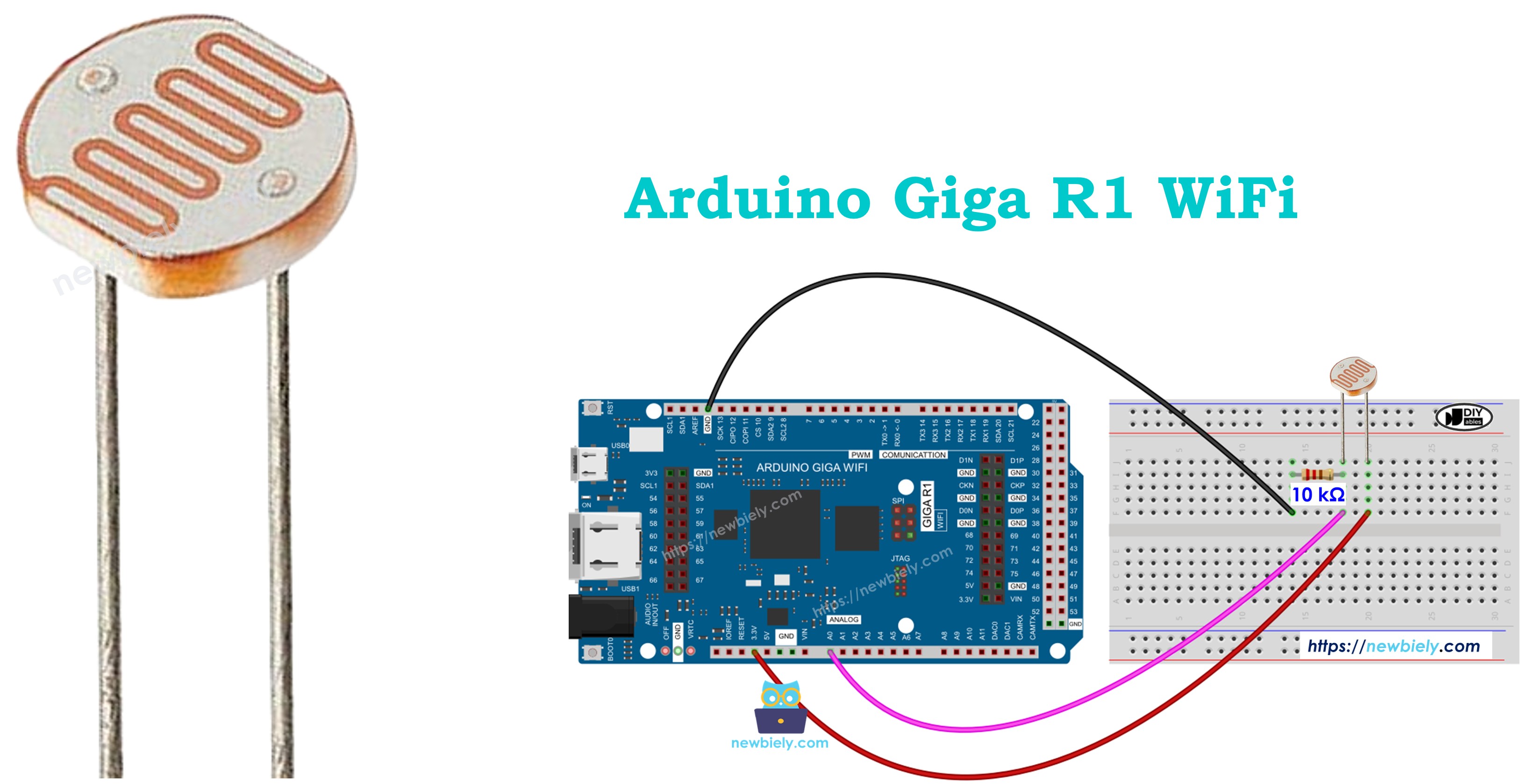
The wiring configuration implements a voltage divider circuit that converts the photoresistor's variable resistance into a proportional voltage signal suitable for the Arduino Giga R1 WiFi's analog input. This fundamental circuit topology ensures optimal signal conditioning and measurement accuracy across the full illumination range.
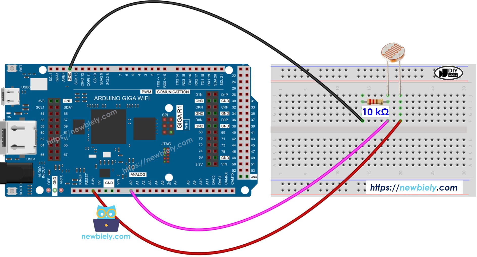
This image is created using Fritzing. Click to enlarge image
Electrical Note: The diagram above shows the minimum viable connection for photoresistor interfacing. For production or extended use, consider adding a 100nF ceramic capacitor from the analog input to ground for noise filtering, and implement a low-pass filter if operating in electrically noisy environments. The 10kΩ reference resistor value provides good sensitivity balance — use 1kΩ for brighter light emphasis or 100kΩ for low-light sensitivity enhancement.
The power supply configuration draws minimal current (typically <0.5mA) from the Arduino's 5V rail, well within the board's current capacity. Total power dissipation remains under 1mW across all operating conditions, ensuring reliable long-term operation without thermal concerns.
| Component Pin | Arduino Giga R1 WiFi Pin |
|---|---|
| Photoresistor Pin 1 | A0 (analog input) |
| Photoresistor Pin 2 | 5V (through 10kΩ resistor) |
| 10kΩ Resistor (other end) | GND |
Arduino Code
The following implementation demonstrates analog light sensing with threshold-based classification logic. The code is structured to handle continuous monitoring by polling the analog input at regular intervals and applying qualitative brightness categorization. Key sections include ADC reading, voltage calculation, and multi-threshold comparison for reliable light level determination.
The analogRead() function interfaces directly with the Arduino Giga R1 WiFi's 12-bit ADC, returning values from 0 to 4095 corresponding to 0-5V input range. The implementation processes these digital values through threshold comparison algorithms to classify ambient light conditions into discrete categories: dark, dim, medium, bright, and very bright. This approach enables robust decision-making for automated lighting control applications.
Detailed Instructions
For initial Arduino Giga R1 WiFi setup, refer to the Arduino Giga R1 WiFi Getting Started guide before proceeding.
- Connect Hardware: Wire the photoresistor and 10kΩ resistor according to the voltage divider configuration shown in the wiring diagram. Verify connections with a multimeter — the voltage at pin A0 should vary from near 0V (bright light) to near 5V (darkness).
- Install Libraries: No additional libraries are required for basic analog reading functionality. The analogRead() function is built into the Arduino core framework and provides direct ADC access.
- Open Arduino IDE: Launch the development environment and ensure the Arduino Giga R1 WiFi board is selected in Tools → Board menu. Verify the correct COM port is selected for USB communication.
- Upload Code: Copy the provided code into a new sketch, compile, and upload to the Arduino Giga R1 WiFi. Monitor the compilation process for any syntax errors or missing dependencies.
- Open Serial Monitor: Set the baud rate to 9600 to match the Serial.begin() configuration in the code. The monitor will display continuous light level readings and qualitative classifications.
- Test Response: Cover the photoresistor with your hand to simulate darkness — readings should increase toward maximum values (4095). Shine a flashlight or expose to bright light — readings should decrease toward minimum values (0-100).
- Verify Thresholds: Observe the transition points between light level categories. Adjust threshold values in the code if needed to match your specific application requirements or ambient lighting conditions.
Technical Note: The analog reading reflects logarithmic light intensity response inherent to photoresistor characteristics. For applications requiring linear brightness representation, implement exponential compensation or lookup table calibration based on known illumination standards.
Serial Monitor Output
The serial monitor displays continuous light sensor readings with timestamp information and qualitative brightness classification. Each output line shows the raw ADC value (0-4095 range) followed by the corresponding light level category based on the implemented threshold algorithm.
Light Sensor and LED
The following code implementation demonstrates automatic LED control based on ambient light conditions — a fundamental building block for smart lighting systems, security applications, and energy-efficient automation. The system monitors light levels continuously and activates LED illumination when darkness is detected, simulating automatic outdoor lighting or emergency backup illumination.
The wiring diagram for LED control integration expands the basic light sensor circuit to include digital output capability for external device control. This configuration enables the Arduino Giga R1 WiFi to function as a complete light-responsive control system.
Electrical Note: The LED current-limiting resistor (220Ω) prevents excessive current draw that could damage the Arduino's digital output pin. For high-power lighting control, implement relay or MOSFET switching circuits to handle larger electrical loads safely.
Application Ideas
Automatic Greenhouse Lighting: Monitor natural daylight levels and activate supplemental grow lights when illumination drops below optimal photosynthesis thresholds. The Arduino Giga R1 WiFi's WiFi connectivity enables remote monitoring and scheduling integration with weather forecast data for predictive lighting control.
Security Perimeter Lighting: Implement dusk-to-dawn automatic lighting for walkways, parking areas, or building perimeters. The dual-core architecture supports concurrent motion detection and wireless alarm communication while maintaining continuous light level monitoring.
Energy-Efficient Office Automation: Integrate with building management systems to control artificial lighting based on available daylight. The system can log illumination patterns, optimize energy consumption, and provide occupancy-correlated lighting analysis for facility management.
Agricultural Light Monitoring: Deploy in livestock facilities or crop storage areas where consistent illumination affects animal behavior or produce quality. Data logging capabilities enable long-term pattern analysis and regulatory compliance documentation.
Photography Studio Automation: Create automatic backdrop lighting or fill-light systems that respond to primary illumination changes. The high ADC resolution enables precise threshold control for consistent photographic lighting conditions.
Solar Panel Tracking Systems: Use light sensors to determine optimal solar panel orientation throughout the day. Multiple sensors can provide directional light gradient information for maximum energy harvesting efficiency.
Challenge Yourself
Challenge: Implement data logging with timestamp recording to track daily light patterns. Store readings to the Arduino Giga R1 WiFi's internal memory or external SD card, then analyze illumination trends over weekly or monthly periods for energy optimization applications.
Challenge: Create a wireless light monitoring network using the Arduino Giga R1 WiFi's connectivity. Multiple sensor nodes can report to a central database, enabling large-area illumination mapping for smart city applications or agricultural monitoring systems.
Challenge: Develop adaptive threshold algorithms that automatically calibrate to local lighting conditions. The system should learn typical day/night patterns and adjust sensitivity to account for seasonal variations or geographical location changes.
Challenge: Integrate multiple light sensors for directional illumination detection. Calculate light gradients to determine sun position or implement shadow-tracking algorithms for automated solar panel positioning or architectural daylighting control.
Challenge: Build a complete home automation interface using the Arduino Giga R1 WiFi's dual-core capability. Combine light sensing with temperature monitoring, motion detection, and wireless control for comprehensive smart home functionality with web-based monitoring dashboard.