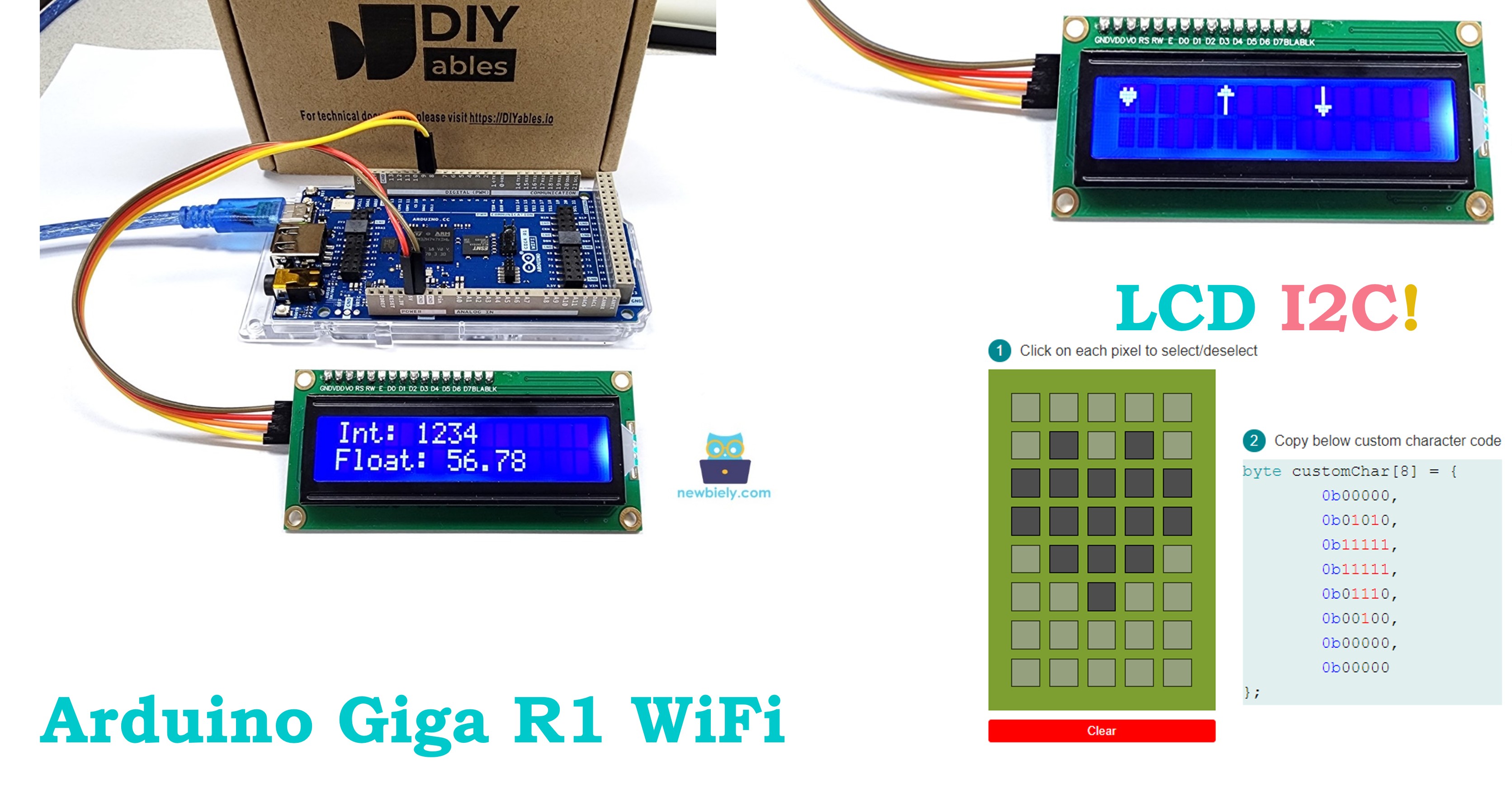
Arduino Giga R1 WiFi LCD I2C
This guide covers LCD I2C integration with the Arduino Giga R1 WiFi. The I2C LCD interface simplifies display integration compared to traditional parallel LCD connections, reducing wiring from 12 pins to just 4 pins.
This tutorial demonstrates implementation using a 16x2 character LCD with I2C backpack, covering basic text display, custom character creation, and advanced formatting techniques.
Hardware Preparation
Or you can buy the following kits:
| 1 | × | DIYables Sensor Kit (18 sensors/displays) |
Additionally, some of these links are for products from our own brand, DIYables .
Buy Note: Alternatively, you can assemble the LCD I2C display using LCD 1602 Display and PCF8574 I2C Adapter Module.
Overview of LCD I2C 16x2
LCD I2C is an integrated display module combining a standard HD44780-compatible character LCD with an I2C interface controller. The I2C interface (typically PCF8574) converts I2C serial commands into parallel control signals for the LCD controller.
The I2C interface operates at 3.3V or 5V logic levels with built-in pull-up resistors. Current consumption is 20-80mA depending on backlight settings. The module supports standard I2C speeds up to 400kHz. Operating voltage is 5V for the LCD panel itself.
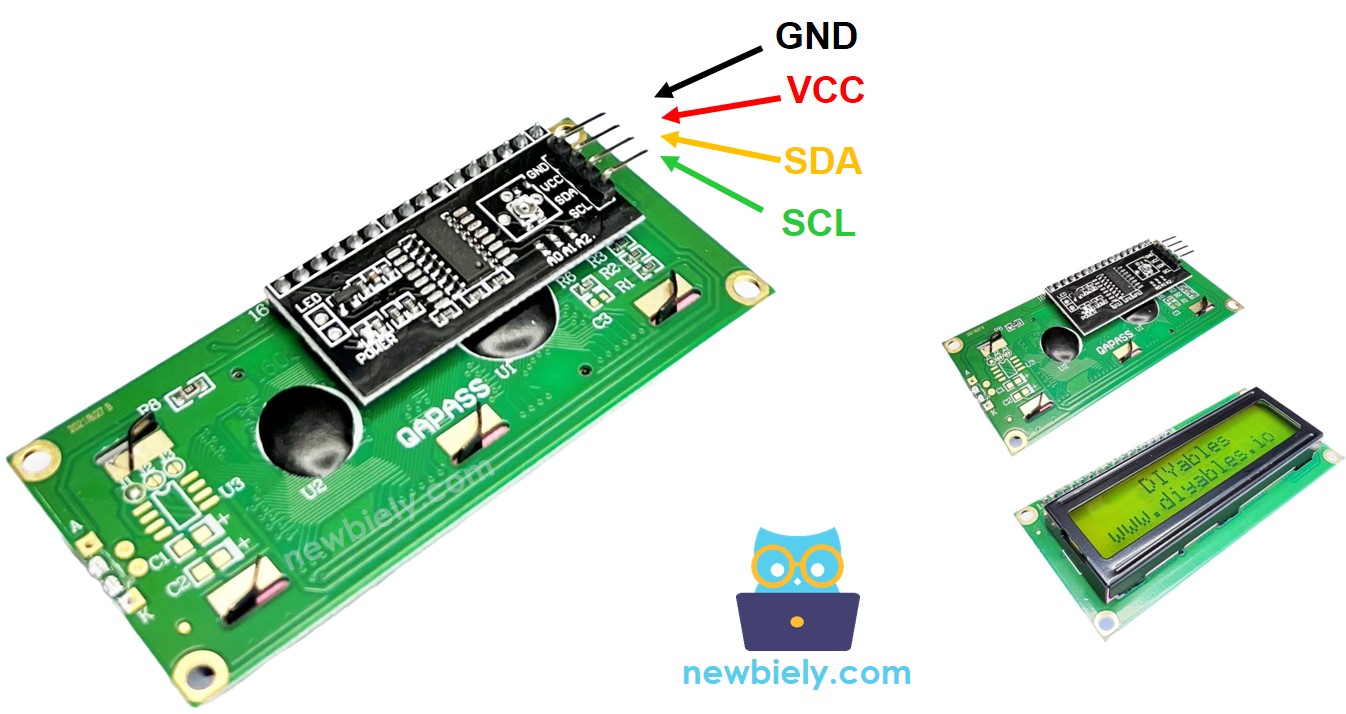
Pinout
The I2C LCD pinout provides a standardized 4-pin interface that simplifies integration with the Arduino Giga R1 WiFi's I2C peripheral. Understanding each pin's electrical characteristics ensures reliable operation and prevents damage to both the LCD module and the Arduino.
- GND: Ground reference (0V). Provides the return path for both logic and power circuits. Connect directly to Arduino GND pin to establish common ground reference. Current capacity should handle the combined LCD and backlight current (typically 60-100mA).
- VCC: Primary power supply (+5V DC). Powers both the LCD panel and the I2C interface controller. Requires clean, regulated 5V supply capable of sourcing 80-120mA continuous current. Connect to Arduino 5V pin, which provides up to 800mA on the Giga R1 WiFi.
- SDA: I2C Serial Data line (bidirectional). Operates at 3.3V logic level with internal pull-up resistors. Connects to Arduino's SDA2 pin (pin 9 on Giga R1 WiFi). Data transmission occurs on this line synchronized with the clock signal.
- SCL: I2C Serial Clock line (output from Arduino). Operates at 3.3V logic level with internal pull-up resistors. Connects to Arduino's SCL2 pin (pin 8 on Giga R1 WiFi). The Arduino generates clock pulses to synchronize data transmission.
The I2C pins include 4.7kΩ pull-up resistors on most modules, making them compatible with the Arduino Giga R1 WiFi's I2C interface without additional components. Signal integrity remains excellent up to 1-meter cable lengths when using proper twisted-pair wiring for SDA/SCL connections.
Electrical Note: The Arduino Giga R1 WiFi's I2C pins are 5V tolerant, ensuring safe operation with 5V-powered LCD modules. For extended cable runs or electrically noisy environments, consider adding 100nF ceramic capacitors between VCC and GND at the LCD end to improve power supply decoupling.
LCD Coordinate
LCD I2C 16x2 organizes display content in a matrix format with 16 columns and 2 rows. The coordinate system uses zero-based indexing where the top-left position is (0,0) and the bottom-right position is (15,1). Understanding this coordinate system is essential for precise text placement and formatting.
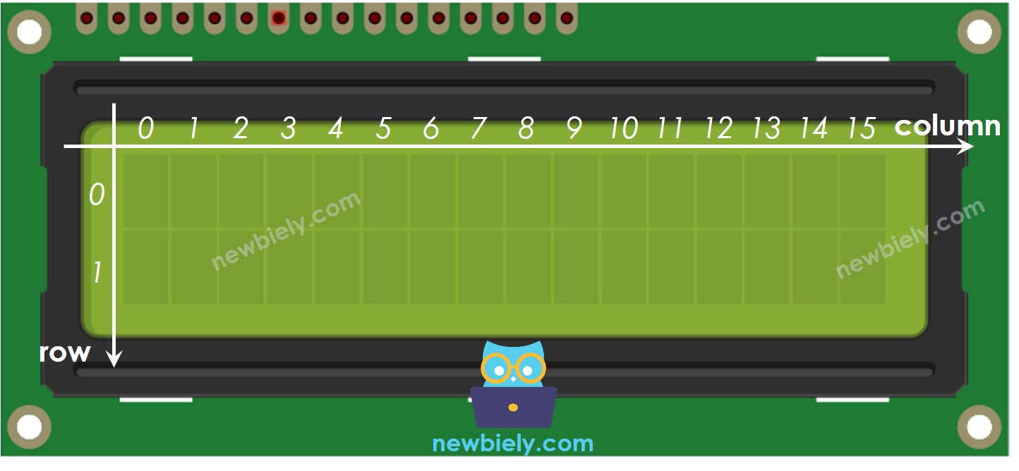
Column indices range from 0-15 (16 total columns) and row indices range from 0-1 (2 total rows). Each position can display one ASCII character or custom-defined character. The LCD controller automatically handles character data storage and refresh, maintaining display content without continuous Arduino intervention.
Character positioning uses the setCursor(column, row) function, where column represents the horizontal position and row represents the vertical position. Attempting to write beyond the display boundaries (column > 15 or row > 1) may cause unpredictable behavior or wrap to unexpected positions depending on the LCD controller's internal addressing mode.
Wiring Diagram
The I2C LCD connection leverages the Arduino Giga R1 WiFi's dedicated I2C interface pins, providing a clean and reliable communication path between the microcontroller and display module. The simplified 4-wire connection reduces potential wiring errors while maintaining full LCD functionality.
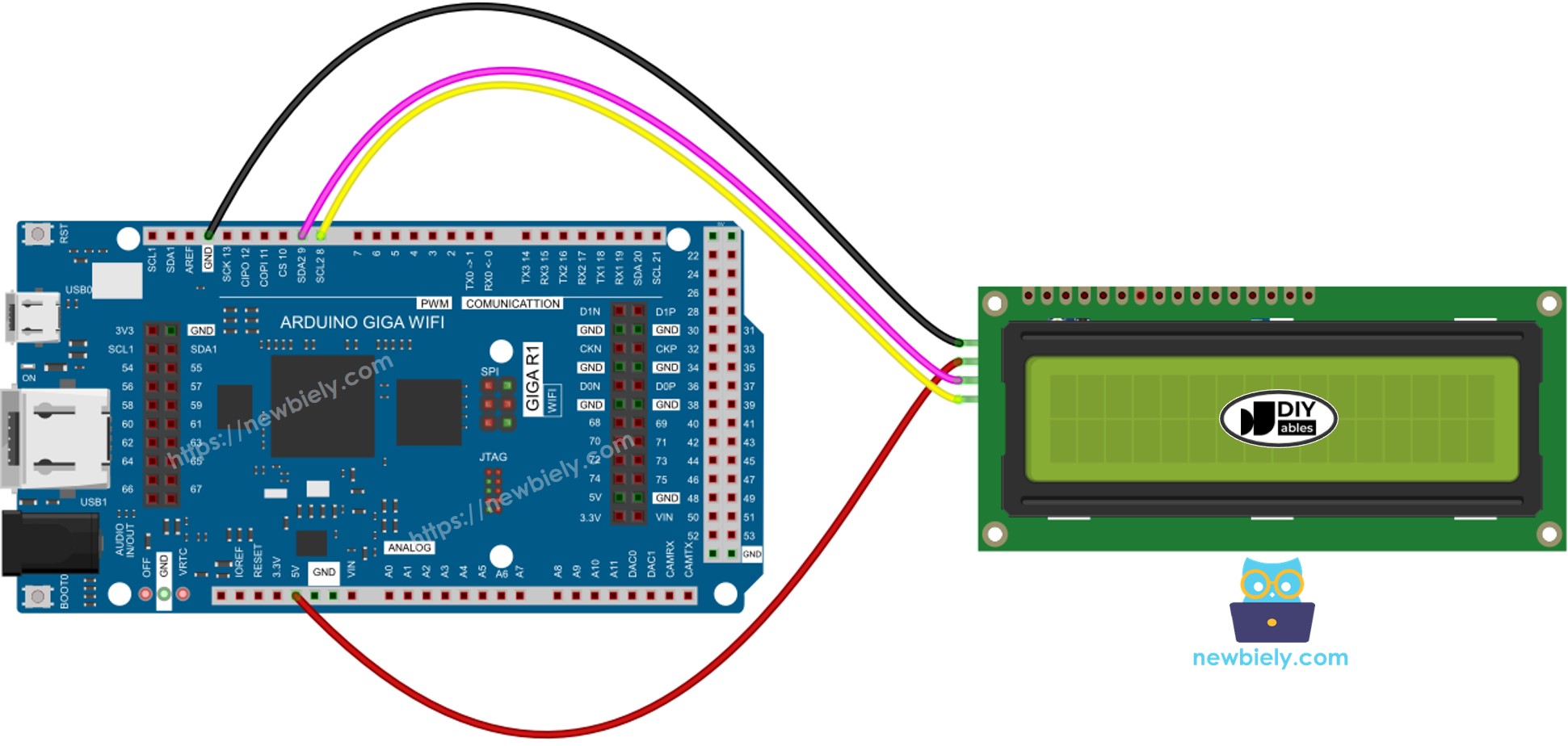
This image is created using Fritzing. Click to enlarge image
Electrical Note: The diagram above shows the minimum viable connection for LCD I2C operation. For production applications or extended operation, consider adding a 100µF electrolytic capacitor between VCC and GND near the LCD module to provide current buffering during backlight transitions and improve overall system stability.
The wiring utilizes the Arduino Giga R1 WiFi's hardware I2C controller, which provides superior timing accuracy and electrical characteristics compared to software-based I2C implementations. The hardware I2C interface supports clock stretching and multi-master operation, enabling integration with other I2C devices on the same bus.
| LCD I2C | Arduino Giga R1 WiFi, Nano | Arduino Giga R1 WiFi |
|---|---|---|
| Vin | 5V | 5V |
| GND | GND | GND |
| SDA | A4 | 9 (SDA2) |
| SCL | A5 | 8 (SCL2) |
Power supply considerations require the Arduino's 5V rail to source 60-100mA for the LCD module. The Giga R1 WiFi's switching regulator easily handles this load when powered via USB or external supply. For battery-powered applications, consider the LCD's power consumption impact on overall system runtime.
How To Program For LCD I2C
The DIYables_LCD_I2C library abstracts the complexity of I2C communication and LCD control, providing a simple interface for text display operations. This library handles I2C protocol management, LCD initialization sequences, and character encoding automatically. The programming approach focuses on high-level display operations rather than low-level I2C transactions.
The library implements efficient communication by caching display state and minimizing I2C transactions. Each function call translates to specific I2C command sequences that configure the LCD controller's internal registers. Understanding this abstraction helps optimize code performance for time-critical applications.
- Include the library:
- Declare a DIYables_LCD_I2C object with I2C address, the number of columns, the number of rows:
- Initialize the LCD.
- Move cursor to the desired position (column_index, row_index)
- Print a message to the LCD.
Advanced operations include custom character creation, backlight control, cursor styling, and display clearing. The library provides comprehensive methods for professional text display applications requiring precise formatting and control.
※ NOTE THAT:
The I2C address of LCD can vary according to the manufacturers. In the code, we used 0x27 that is specified by DIYables manufacturer. Common alternative addresses include 0x3F, 0x26, and 0x20. Use the I2C scanner code in the troubleshooting section to detect your specific module's address.
Arduino Code
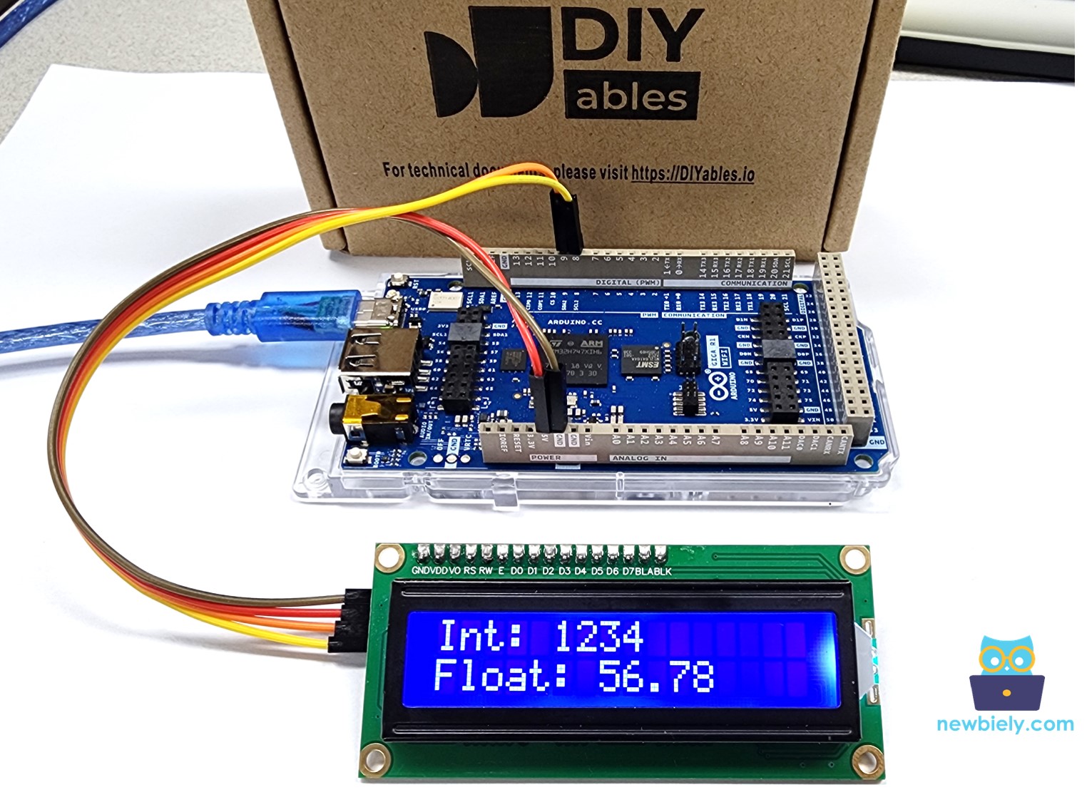
The following implementation demonstrates core LCD I2C functionality with the Arduino Giga R1 WiFi. The code structure separates initialization from display operations, following embedded systems best practices for hardware interface management. Key sections handle LCD setup, text positioning, and display timing control.
The example showcases alternating display content to demonstrate cursor positioning and text clearing operations. The 2-second delay provides sufficient time for human readability while demonstrating continuous display updates. This pattern forms the foundation for more complex applications requiring dynamic content display.
Detailed Instructions
For initial Arduino Giga R1 WiFi setup, refer to the Arduino Giga R1 WiFi Getting Started guide before proceeding.
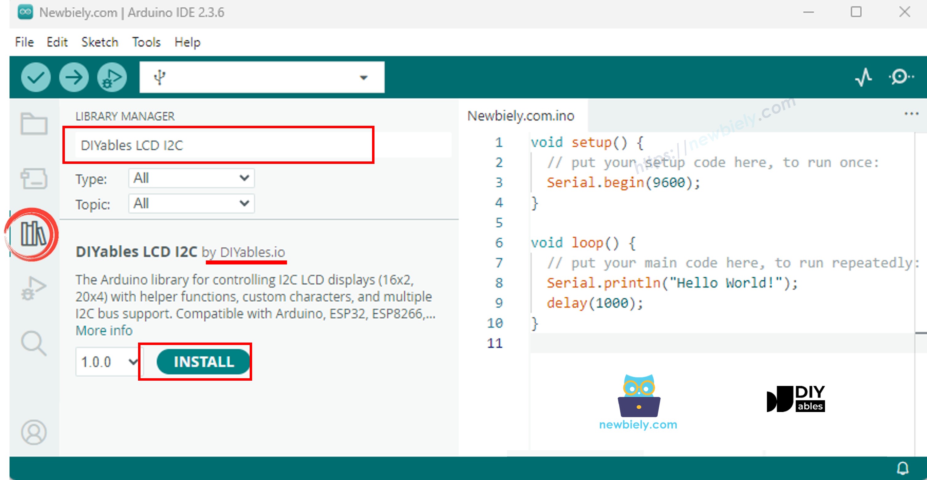
- Install Library: Navigate to the Libraries icon on the left bar of the Arduino IDE. Search "DIYables LCD I2C", then find the DIYables_LCD_I2C library by DIYables. This library provides optimized I2C communication and comprehensive LCD control functions.
- Connect Hardware: Wire the LCD I2C module to the Arduino Giga R1 WiFi following the wiring diagram above. Ensure solid connections on SDA2 (pin 9), SCL2 (pin 8), VCC (5V), and GND pins. Verify power supply connections before proceeding to prevent damage.
- Load Code: Copy the provided code example and open it in Arduino IDE. The code demonstrates basic text display and cursor positioning operations. Review the I2C address (0x27) and modify if your module uses a different address.
- Upload Program: Click the Upload button in Arduino IDE to compile and transfer the code to the Arduino Giga R1 WiFi. The compilation process validates library dependencies and generates optimized machine code for the STM32H747XI processor.
- Verify Operation: Observe the LCD display showing alternating text messages. The display should clearly show "Arduino" and "GetStarted.com" for 2 seconds, then switch to "DIYables" and "www.diyables.io". If text appears dim, adjust the onboard potentiometer.
- Customize Content: Modify the text strings and cursor positions to experiment with different display layouts. Try different coordinate combinations and observe how text positioning affects the overall display appearance.
- Test Advanced Features: Experiment with additional LCD functions such as lcd.cursor() for visible cursor, lcd.blink() for blinking cursor, and lcd.noBacklight() for backlight control. These functions provide enhanced user interface capabilities.
Technical Note: The DIYables_LCD_I2C library caches certain display states to minimize I2C bus traffic. For applications requiring high-frequency updates, consider buffering display content and updating only changed characters to optimize performance and reduce I2C overhead.
Serial Monitor Output
The LCD I2C tutorial produces visual output on the connected display rather than serial communication. However, for debugging and development purposes, you can add Serial.print() statements to monitor program execution:
Do More with LCD
Custom Character
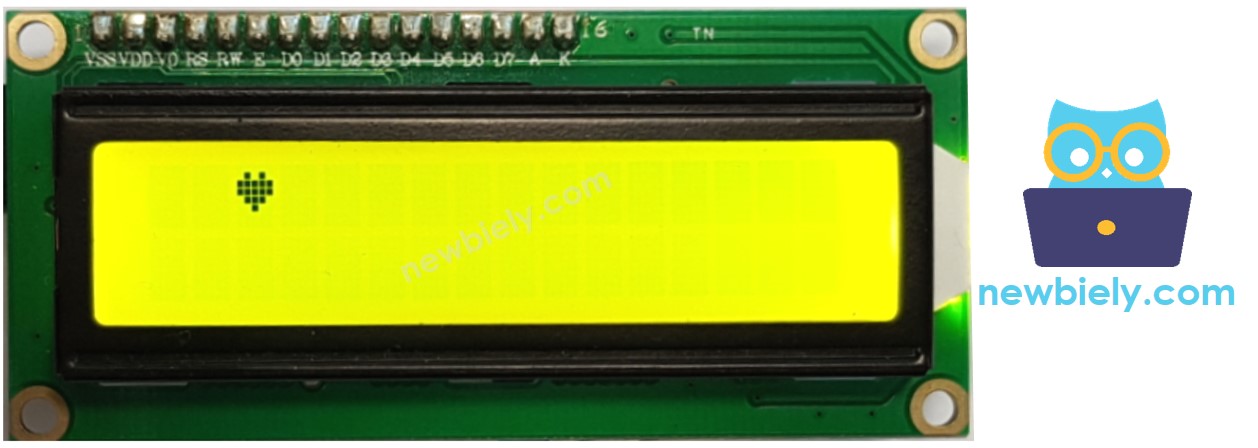
lcd.print() function supports only ASCII characters. If you want to display a special character or symbol (e.g. heart, angry bird), you need to use the below character generator.
LCD 16x2 can display 32 characters (2 rows and 16 columns). Each character is composed of 40 pixels (8 rows and 5 columns).
The character generator represents a character (40 pixels). You just need to do the following steps:
Result on LCD:
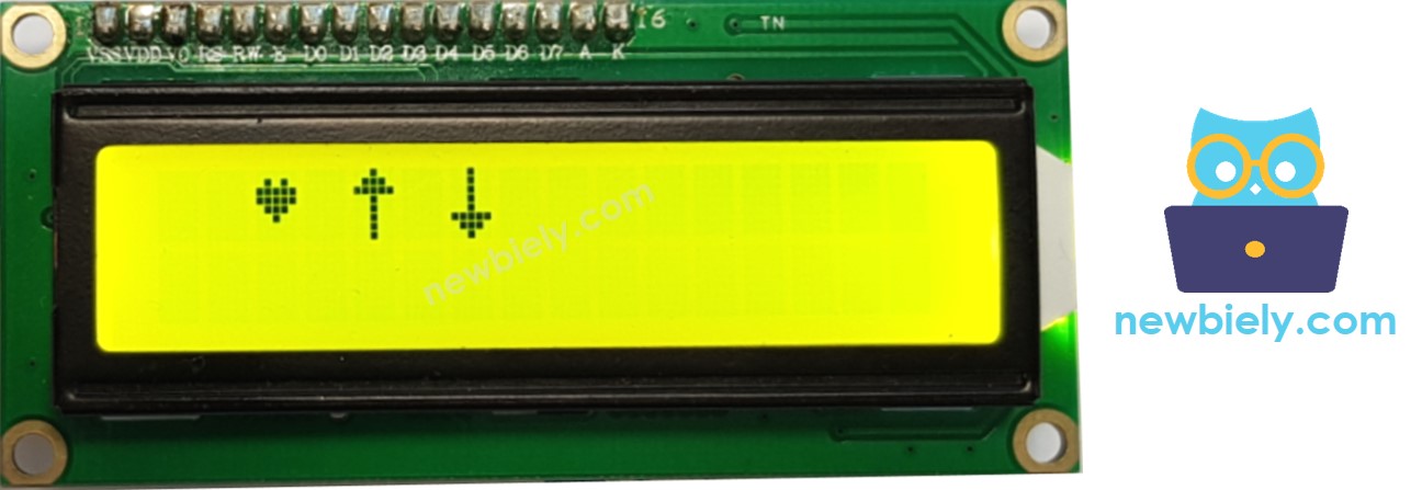
Multiple custom characters
We can create up to 8 custom characters (indexed 0 to 7). The below example creates and displays three characters.
Result on LCD:
Summary: how to use custom character on LCD
- Use the above character generator to create binary code for the custom character.
- Declare the binary code for the custom character (copy from above step)
- Create custom character and assign to an index value (from 0 to 7) in setup() function
- Print the custom character in LCD anytime, anywhere (in setup() or loop() function)
Other functions
Add the below functions into loop() function one by one. And add delay(5000) after each function
The DIYables_LCD_I2C library provides comprehensive display control functions for professional applications. These functions enable cursor management, display clearing, backlight control, and text formatting operations essential for user interface development.
- Clear LCD screen
- Move the cursor to the upper-left of the LCD
- Move the cursor to the a position (column, row)
- Display the LCD cursor
- Hides the LCD cursor.
- Display the blinking LCD cursor
- Turns off the blinking LCD cursor.
Additional advanced functions at LiquidCrystal Library Reference