Arduino Giga R1 WiFi Electromagnetic Lock
This guide covers electromagnetic lock (EM lock) integration with the Arduino Giga R1 WiFi. The electromagnetic lock provides secure electronic door control through electromagnetic force rather than mechanical mechanisms.
This tutorial walks through relay control circuits, power management, and programming logic. You'll implement a complete electromagnetic lock control system using a relay interface to handle the high-voltage requirements.
An alternative to the Electromagnetic Lock is Solenoid Lock. You can learn more in Arduino - Solenoid Lock tutorial
Hardware Preparation
Or you can buy the following kits:
| 1 | × | DIYables Sensor Kit (18 sensors/displays) |
Additionally, some of these links are for products from our own brand, DIYables .
Overview of Electromagnetic Lock
Electromagnetic locks operate through electromagnetic force with holding forces ranging from 280 lbs (1,200 N) to over 1,200 lbs (5,400 N). They operate at 12V, 24V, or 48V DC with response time typically <100ms.
When current flows through the electromagnet coil, it generates a magnetic field that attracts the ferromagnetic armature plate. Electromagnetic locks offer instantaneous operation, no mechanical wear, silent operation, and fail-safe operation (locks release during power failure). They consume 150-500mA continuously when locked.
Pinout
The pinout configuration determines the electrical connection strategy for reliable electromagnetic lock operation. Correct wiring is essential — an incorrect power supply connection may damage the electromagnet coil or produce insufficient holding force.
Electromagnetic Lock includes two components:
- One electromagnet with two pins
- One armature plate
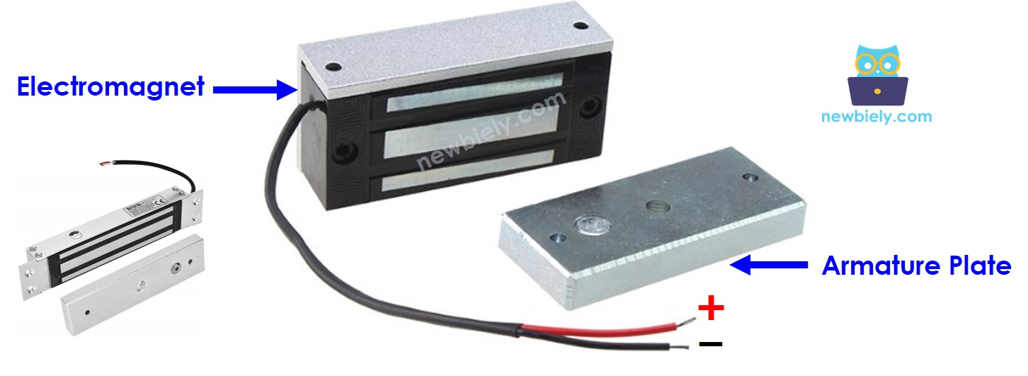
Electromagnet Connections:
- POSITIVE (+): DC power input, typically 12V, 24V, or 48V depending on lock specification. Connect to relay common output to enable Arduino control.
- NEGATIVE (-): DC power return path. Connect to power supply ground. Ensure adequate current handling capacity for the lock's rated current draw.
Armature Plate: No electrical connections. Ferromagnetic plate that provides the attractive surface for electromagnetic locking. Physical installation requires precise alignment with the electromagnet face for maximum holding force.
Power Requirements: Electromagnetic locks typically draw 150-500mA continuous current when energized. Verify the power supply can deliver sufficient current with adequate margin. Voltage drop under load can significantly reduce holding force.
How It Works
The electromagnetic lock operates on electromagnetic induction principles combined with magnetic attraction physics. When the electromagnet coil is energized with DC current, it creates a concentrated magnetic field across the air gap between the electromagnet face and the armature plate.
- When the electromagnet is powered, current passing through the electromagnet coil creates a magnetic flux that causes the ferromagnetic armature plate to attract to the electromagnet with considerable force (typically 280-1200+ lbs holding force) ⇒ a locking action
- When the electromagnet is NOT powered, there is no magnetic flux, the armature plate does NOT attract to the electromagnet and can be separated with minimal force ⇒ an unlocking action
The holding force is determined by several factors: electromagnet coil design, supply voltage, current draw, air gap distance, and armature plate material properties. Even small air gaps (due to dirt, misalignment, or wear) can significantly reduce holding force. Professional installations typically specify maximum air gap tolerances of 0.003-0.006 inches.
※ NOTE THAT:
The electromagnetic lock usually uses 12V, 24V or 48V power supply with current requirements of 150-500mA. Therefore, we CANNOT connect the electromagnetic lock directly to Arduino pin (which provides only 3.3V/5V at low current). We must connect it to Arduino pin via a relay module that can switch the high-voltage, high-current lock circuit safely.
If we connect the electromagnetic lock to a relay (normally open mode):
- When relay is open, the electromagnet circuit is broken, door is unlocked
- When relay is closed, the electromagnet circuit is complete, door is locked
By connecting the Arduino Giga R1 WiFi to the relay control input, we can program precise timing and control logic for the electromagnetic lock. The Arduino's digital output provides the 5V signal needed to energize the relay coil, while the relay contacts handle the higher voltage and current required by the electromagnetic lock. Learn more about relay interfacing in Arduino - Relay tutorial.
For proper installation, the armature plate is attached to the door or moving component, while the electromagnet is mounted to the fixed door frame. The two components must achieve face-to-face contact when the door closes to maximize holding force and ensure security.
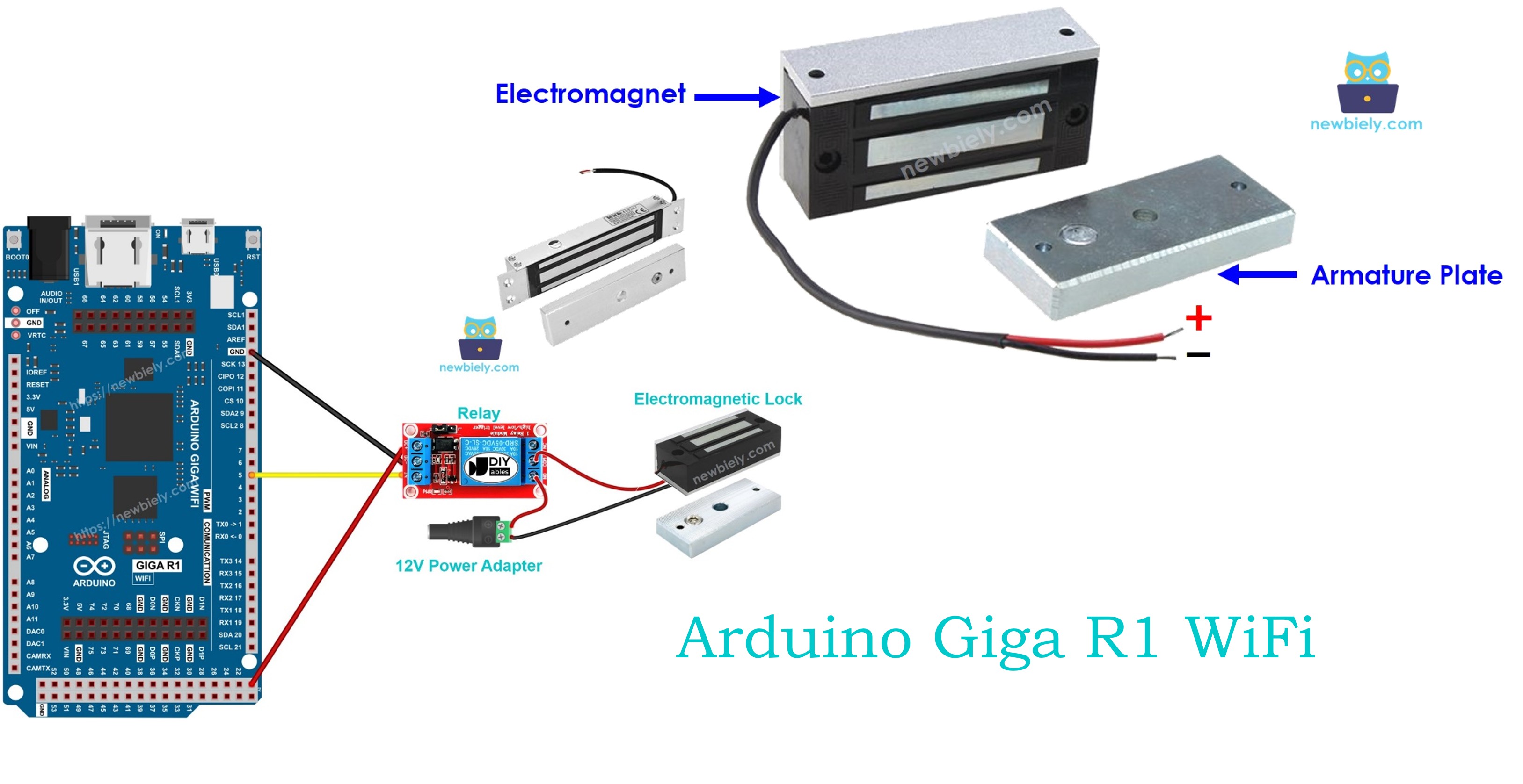
Wiring Diagram
The following wiring configuration demonstrates the safe integration of an electromagnetic lock with the Arduino Giga R1 WiFi using a relay interface. This approach isolates the low-voltage Arduino circuitry from the higher-voltage electromagnetic lock circuit.
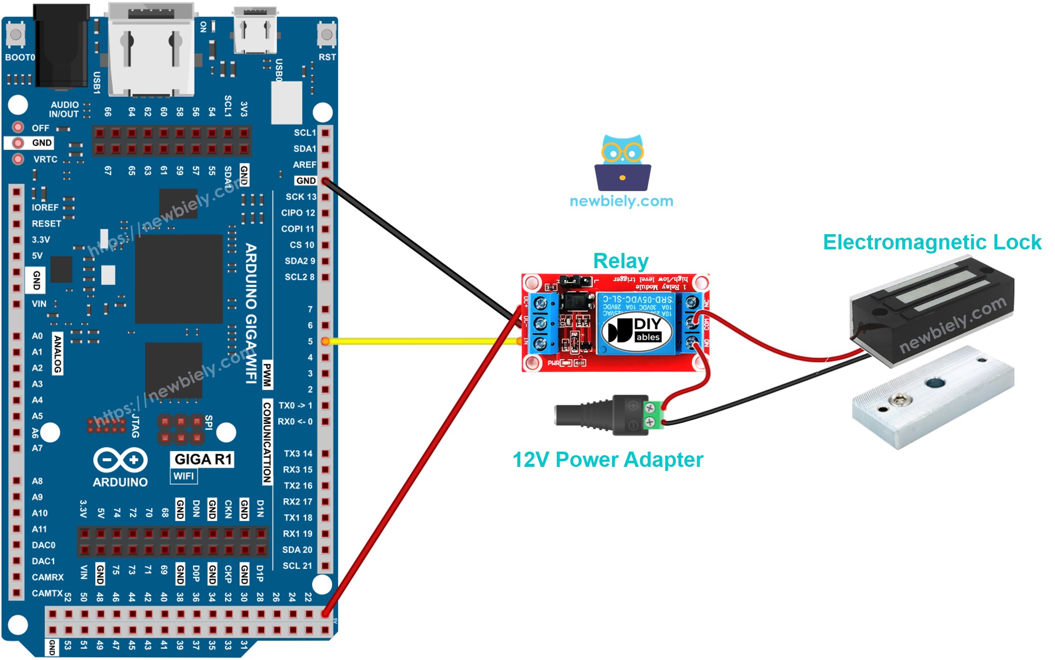
This image is created using Fritzing. Click to enlarge image
Electrical Note: The diagram above shows the minimum viable connection for electromagnetic lock control. For production or extended use, consider adding flyback diodes across the electromagnetic lock terminals to suppress inductive kickback, fusing the 12V supply circuit for overcurrent protection, and using optically isolated relays to provide additional electrical isolation between the Arduino and lock circuits.
Power Supply Considerations: The electromagnetic lock requires a dedicated 12V power supply capable of delivering the lock's rated current (typically 150-500mA) with at least 20% overhead. The Arduino Giga R1 WiFi operates from USB power or external 5-12V supply. Using separate power supplies prevents voltage sag issues that could cause Arduino resets when the lock energizes.
| Component Pin | Arduino Giga R1 WiFi Pin | Function |
|---|---|---|
| Relay VCC | 5V | Relay module power supply |
| Relay GND | GND | Common ground reference |
| Relay IN | Digital Pin 7 | Relay control signal |
| EM Lock (+) | Relay NO Common | Switched 12V supply to lock |
| EM Lock (-) | 12V Supply (-) | Lock power return path |
| DC Jack (+) | Relay NO | 12V positive supply input |
| DC Jack (-) | GND (12V Supply) | 12V supply ground reference |
Arduino Code
The following implementation demonstrates relay-controlled electromagnetic lock operation with timing-based control logic. The code is structured to handle safe lock/unlock sequences with clear state transitions. Key sections include relay initialization, timing control, and state management with serial output for debugging and monitoring.
This implementation uses the digitalWrite() function to control the relay state, which in turn controls the electromagnetic lock power circuit. The relay acts as an electrical switch, allowing the Arduino's low-voltage digital output to control the high-voltage electromagnetic lock circuit safely. The code includes timing delays to demonstrate automatic lock/unlock cycles suitable for testing and basic applications.
Detailed Instructions
For initial Arduino Giga R1 WiFi setup, refer to the Arduino Giga R1 WiFi Getting Started guide before proceeding.
- Wire the Circuit: Connect the electromagnetic lock system according to the wiring diagram. Verify all connections before applying power. The relay should click audibly when the Arduino pin goes HIGH.
- Connect Power Supplies: Connect the 12V power adapter to the DC jack and verify proper voltage with a multimeter. Connect the Arduino Giga R1 WiFi via USB cable. The Arduino should power up and the onboard LED should illuminate.
- Open Arduino IDE: Launch the Arduino IDE and ensure the Arduino Giga R1 WiFi board is selected in Tools > Board menu. Select the correct COM port for your connected Arduino.
- Copy and Upload Code: Copy the electromagnetic lock control code into a new Arduino IDE sketch. Click the Upload button to compile and transfer the code to the Arduino Giga R1 WiFi. Monitor the IDE output window for successful upload confirmation.
- Verify Serial Output: Open the Serial Monitor (Tools > Serial Monitor) and set the baud rate to 9600. You should see "Door Locked" and "Door Unlocked" messages alternating every 5 seconds, indicating proper code execution.
- Test Physical Operation: Place the armature plate close to the electromagnet. You should observe strong magnetic attraction when "Door Locked" appears in the serial monitor, and immediate release when "Door Unlocked" is displayed. The relay should produce an audible click during each state transition.
- Measure Holding Force: With the door locked, attempt to separate the armature plate from the electromagnet. The holding force should be substantial (typically 280+ lbs for standard locks). If the force seems weak, check for air gaps, verify supply voltage, and ensure proper electrical connections.
Technical Note: The 5-second timing cycle is suitable for demonstration and testing purposes. In practical access control applications, implement event-driven control based on user input (keypads, RFID readers, network commands) rather than fixed timing cycles. Consider implementing safety timeouts and emergency unlock procedures for compliance with fire safety regulations.
Serial Monitor Output
Applications and Project Ideas
Access Control System: Implement a complete door access control system with RFID card authentication. The Arduino Giga R1 WiFi's WiFi capabilities enable remote monitoring and logging of access events to a central server. Integrate with user databases and time-based access restrictions for comprehensive security management.
Smart Building Integration: Create a networked door control system that interfaces with building automation systems. The Arduino Giga R1 WiFi can communicate via WiFi with building management software to coordinate door locking with HVAC schedules, occupancy sensors, and fire safety systems for intelligent building operation.
Emergency Override System: Develop a fail-safe electromagnetic lock controller with multiple override mechanisms. Implement fire alarm integration, emergency button inputs, and power failure detection. The dual-core architecture of the Arduino Giga R1 WiFi enables simultaneous monitoring of multiple safety inputs while maintaining reliable lock control.
Multi-Door Security Network: Build a distributed security system controlling multiple electromagnetic locks from a central Arduino Giga R1 WiFi hub. Use relay expansion modules and implement door status monitoring with magnetic reed switches. The system can log entry/exit events and provide real-time security status via web interface.
Biometric Door Lock: Integrate fingerprint sensors or cameras with the electromagnetic lock control system. The Arduino Giga R1 WiFi's processing power can handle biometric data processing and user authentication while maintaining responsive lock control. Add LCD displays for user feedback and system status indication.
IoT-Enabled Remote Lock: Create a smartphone-controlled electromagnetic lock system using the Arduino Giga R1 WiFi's WiFi capabilities. Implement secure communication protocols, user authentication, and remote monitoring. Include features like temporary access codes, activity logging, and integration with home automation platforms.
Video Section
The accompanying video demonstrates the complete hardware assembly process and live code execution. It covers the relay wiring connections in detail, shows the electromagnetic lock engagement and disengagement cycles, and displays the expected serial monitor output with timing verification. Pay particular attention to the safety considerations when working with the 12V power supply and the proper sequence for testing the magnetic holding force.
Challenge Yourself
Challenge: Implement door status monitoring by adding a magnetic reed switch to detect when the door is actually closed. Modify the code to only engage the electromagnetic lock when the door position sensor confirms the door is properly closed, preventing lock activation on an open door.
Challenge: Add a keypad interface for secure access code entry. Implement a multi-digit code verification system with lockout protection after failed attempts. Use the Arduino Giga R1 WiFi's memory capacity to store multiple valid access codes with different privilege levels.
Challenge: Create a web-based lock control interface using the Arduino Giga R1 WiFi's WiFi capabilities. Implement a secure HTTP server that allows authorized users to remotely lock/unlock the door via web browser. Include real-time status updates and access logging with timestamp records.
Challenge: Implement power consumption monitoring by measuring the electromagnetic lock current draw using a current sensor module. Log power usage patterns and detect potential lock malfunctions based on abnormal current consumption. The dual-core architecture enables simultaneous power monitoring and lock control tasks.
Challenge: Design an integrated fire safety system that automatically unlocks all electromagnetic locks when a fire alarm input is detected. Implement backup battery power switching and emergency communication protocols. Add visual and audible indicators for emergency unlock status using the Arduino Giga R1 WiFi's multiple GPIO resources.