Arduino Giga R1 WiFi Control Heating Element
This guide covers heating element control with the Arduino Giga R1 WiFi using relay-based switching. The tutorial demonstrates ON/OFF heating control using a 12V heating element switched through an electromagnetic relay.
This tutorial covers hardware requirements, relay-based control, wiring implementation, and practical code examples. You'll implement a working heating control system suitable for thermal management projects.
Hardware Preparation
Or you can buy the following kits:
| 1 | × | DIYables Sensor Kit (18 sensors/displays) |
Additionally, some of these links are for products from our own brand, DIYables .
Overview of Heating Element
Heating elements are resistive electrical devices that convert electrical current to thermal energy through Joule heating. The 12V DC heating elements typically feature power ratings from 5W to 50W, with current consumption from 0.4A to 4.2A at rated voltage.
Integration requires relay-based switching for electrical isolation, as heating elements draw significant current far exceeding the microcontroller's GPIO limits. Thermal response follows exponential curves with time constants typically ranging from 30 seconds to several minutes.
Pinout
Understanding the pinout configuration is critical for safe and reliable heating element integration. Incorrect connections can result in component damage, inadequate heating performance, or potentially dangerous electrical faults that may cause overheating or fire hazards.
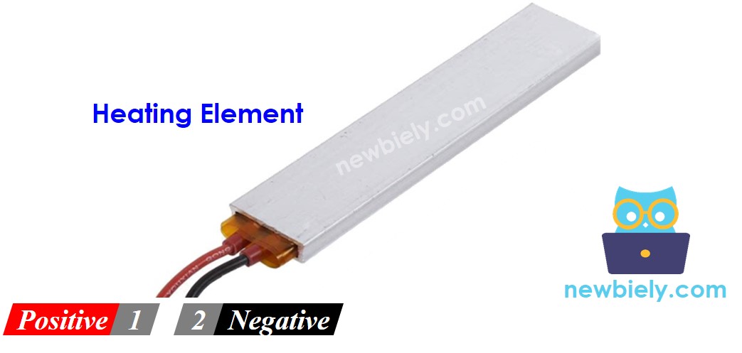
Heating elements typically feature a two-wire configuration with the following specifications:
Positive (+) pin (red wire): DC positive input, 12V nominal. Connects to the positive terminal of the DC power supply through the relay's normally open (NO) contact. Maximum voltage tolerance is typically ±10% (10.8V to 13.2V). Reverse polarity protection is not inherent — incorrect connection may damage the element.
Negative (-) pin (black wire): DC negative/ground return, 0V reference. Connects directly to the GND terminal of the DC power supply and Arduino Giga R1 WiFi ground plane. This connection provides the current return path and maintains electrical safety through proper grounding.
The heating element operates as a purely resistive load with no polarity sensitivity in most applications. However, some specialized elements may incorporate internal thermal sensors or safety devices that require specific polarity orientation. Current flow through the resistive element generates heat according to P = V²/R, where power dissipation increases quadratically with applied voltage.
Common wiring errors include insufficient wire gauge for current handling (minimum 18 AWG recommended for currents above 2A), loose connections causing arcing and hotspots, and inadequate relay current ratings. Always verify that relay contacts are rated for at least 125% of the heating element's maximum current draw to ensure reliable switching under inductive loads.
How to Control Heating Element
Heating element control requires relay-based switching due to the significant power requirements that exceed microcontroller GPIO capabilities. When a 12V heating element receives power from a 12V DC supply through closed relay contacts, resistive heating occurs according to Joule's law (P = I²R). The Arduino Giga R1 WiFi controls the heating element indirectly by energizing the relay coil, which mechanically closes the power contacts to complete the heating circuit.
The control architecture employs electrical isolation between the low-voltage logic (3.3V Arduino GPIO) and high-current heating circuit (12V, potentially several amperes). This isolation prevents ground loops, reduces noise coupling, and provides safety protection against power supply faults. The relay's electromagnetic coil typically requires 5V at 50-100mA for activation, well within the Arduino Giga R1 WiFi's GPIO drive capability when using appropriate relay modules.
Control timing considerations include relay mechanical switching delays (typically 5-15ms) and heating element thermal time constants (30 seconds to minutes). For precise temperature control applications, these delays must be considered in control loop design. The Arduino Giga R1 WiFi's dual-core architecture enables simultaneous temperature monitoring and relay control without timing conflicts.
If you do not know about relay operation principles, including pinout identification, switching characteristics, and programming techniques, refer to the comprehensive Arduino - Relay tutorial for detailed implementation guidance and safety considerations.
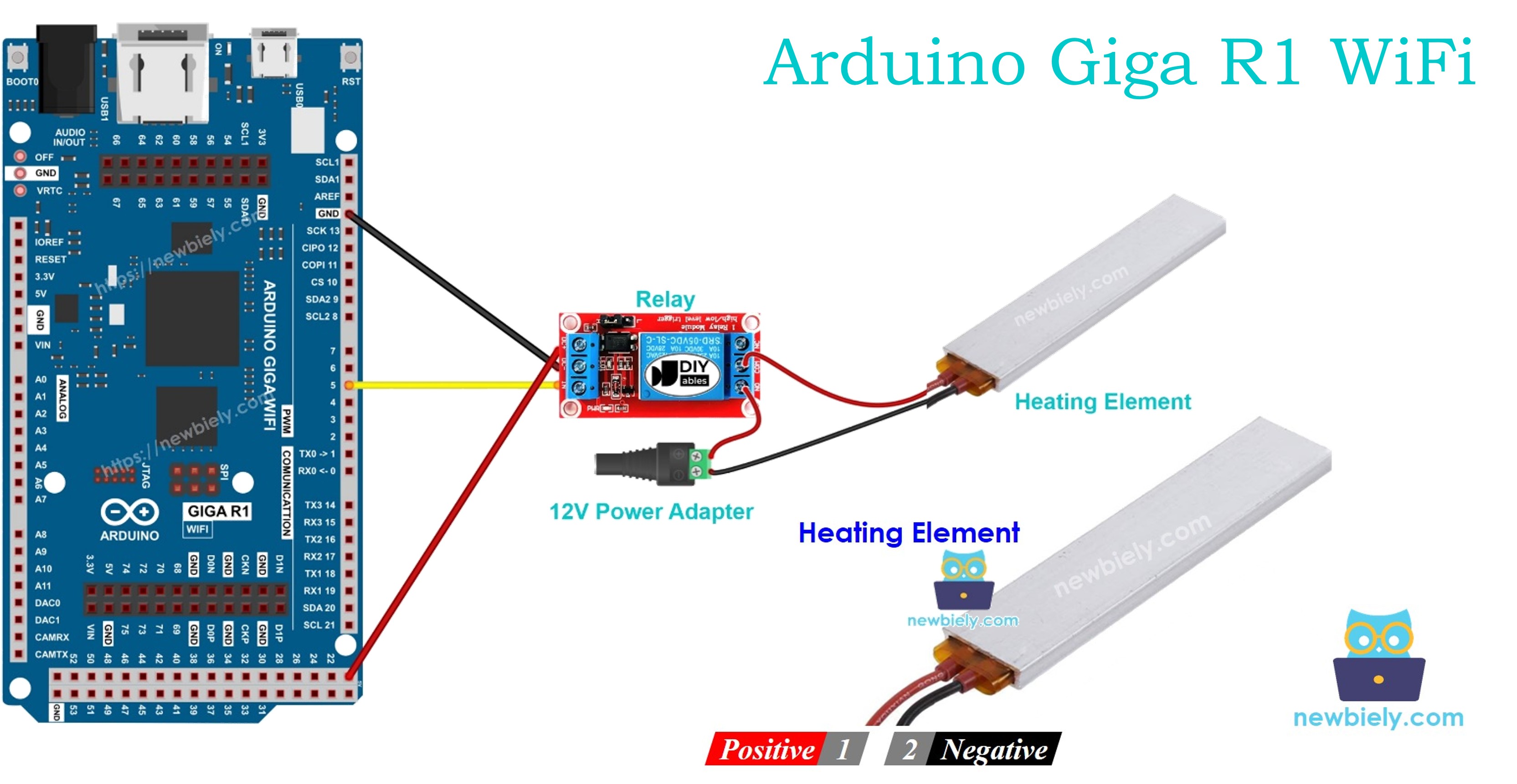
Wiring Diagram
The wiring implementation demonstrates proper electrical isolation between the Arduino Giga R1 WiFi's low-voltage logic and the heating element's high-current power circuit. This configuration ensures safe operation while providing reliable switching control through electromagnetic relay operation.
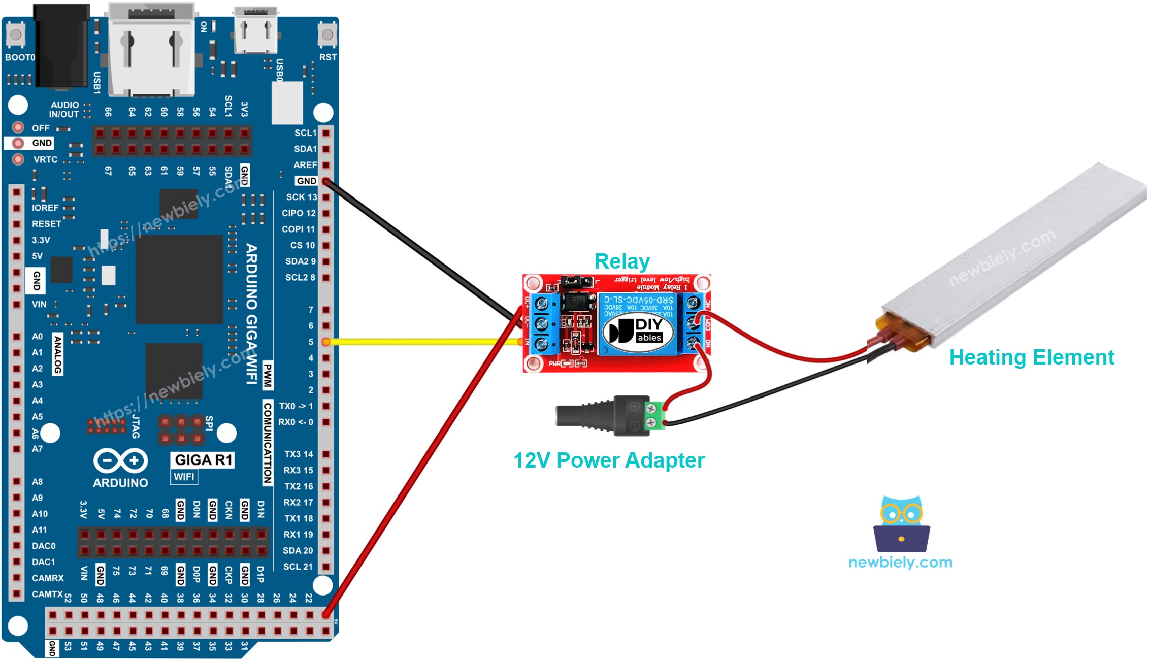
This image is created using Fritzing. Click to enlarge image
Electrical Note: The diagram above shows the minimum viable connection for heating element control. For production applications or extended operation, consider adding a flyback diode across the relay coil terminals, implementing current monitoring through a shunt resistor, and incorporating thermal protection such as a thermal fuse or temperature sensor feedback loop to prevent overheating conditions.
Power supply considerations include ensuring adequate current capacity — the 12V adapter must provide at least 125% of the heating element's rated current to prevent voltage droop and ensure reliable operation. Typical 12V heating elements consume 1-4A, requiring power supplies rated for 15-60W depending on the specific element specifications.
| Component Pin | Arduino Giga R1 WiFi Pin |
|---|---|
| Relay VCC | 5V |
| Relay GND | GND |
| Relay IN | Digital Pin 7 |
| Heating Element (+) | Relay NO Contact |
| Heating Element (-) | 12V Power Supply GND |
| 12V Power Supply (+) | Relay Common Contact |
| 12V Power Supply (-) | Arduino GND (shared) |
Arduino Code
The following implementation demonstrates relay-based heating element control using digital GPIO switching. The code structure handles timing-based ON/OFF cycling with clear state management and diagnostic output. Key sections include initialization of the relay control pin, main timing loop implementation, and serial monitoring for operational verification.
The control logic employs digitalWrite() functions to assert HIGH (relay energized, heating ON) and LOW (relay de-energized, heating OFF) states on the designated GPIO pin. The implementation uses delay() functions for timing control, though more sophisticated applications would employ millis()-based non-blocking timing to enable concurrent operations such as temperature monitoring or user interface handling.
Library dependencies are minimal for this basic implementation — only standard Arduino core functions are required. The code initializes serial communication at 9600 baud for operational monitoring and debugging. Pin 7 is configured as OUTPUT mode to drive the relay control input, providing sufficient current (25mA typical) to activate standard 5V relay modules.
The below code repeatedly turns the Heating Element ON for five seconds and OFF for five seconds, creating a 10-second cycle period suitable for demonstration and basic heating applications:
Detailed Instructions
Prerequisites: Arduino IDE installed and the Giga R1 WiFi board package configured. Refer to the Getting Started guide for setup instructions if the Arduino development environment is not yet configured.
- Connect Hardware: Wire the heating element, relay, and power supply according to the wiring diagram. Verify all connections are secure and properly insulated. The relay should click audibly when manually connected to 5V, indicating proper mechanical operation.
- Verify Power Supply: Connect the 12V adapter to the DC power jack and confirm voltage output with a multimeter. Voltage should read 11.5-12.5V under no-load conditions. Ensure current rating exceeds the heating element's specifications by at least 25%.
- Connect Arduino: Attach the Arduino Giga R1 WiFi to the PC via USB cable. The board should enumerate as a USB device and appear in the Arduino IDE's port selection menu. If the board is not recognized, install the STM32H7 board package through the Board Manager.
- Upload Code: Open Arduino IDE, select "Arduino Giga" as the board type and the appropriate COM port. Copy the provided code into a new sketch, verify compilation without errors, then upload to the Arduino Giga R1 WiFi. The upload process typically completes within 10-15 seconds.
- Monitor Operation: Open the Serial Monitor (Tools > Serial Monitor) and set the baud rate to 9600. You should observe "Heating Element is ON" and "Heating Element is OFF" messages alternating every 5 seconds, confirming proper code execution and timing.
- Verify Heating: Carefully monitor the heating element's temperature rise during ON cycles. The element should begin warming within 10-30 seconds of activation. Use an infrared thermometer or thermocouple for temperature measurement — avoid direct contact with heating surfaces.
- Test Relay Operation: Listen for relay clicking during state transitions. The mechanical relay should produce audible switching sounds coinciding with the serial monitor messages. Absence of clicking indicates wiring errors or insufficient drive current.
Technical Note: For applications requiring precise temperature control, replace the fixed 5-second timing with temperature-based feedback control using a thermistor or digital temperature sensor. The Arduino Giga R1 WiFi's dual-core architecture enables simultaneous temperature monitoring and PID control loop execution without timing interference.
Serial Monitor Output
WARNING
Please be careful. It can burn you and your house. This is a serious topic, and we want you to be safe. If you're NOT 100% sure what you are doing, do yourself a favor and don't touch anything. Ask someone who knows! We do NOT take any responsibility for your safety.
Code Explanation
Read the line-by-line explanation in comment lines of code!
Application Ideas
Industrial Process Heating: Implement controlled heating for chemical processes, plastic molding, or material curing applications. The Arduino Giga R1 WiFi's dual-core processing enables simultaneous temperature monitoring, PID control loop execution, and data logging to SD card or cloud storage for process documentation and quality control.
Smart Home Heating System: Create zone-based heating control for residential applications with WiFi connectivity for remote monitoring and scheduling. The integrated WiFi capability allows integration with home automation platforms, mobile app control, and energy consumption monitoring for optimal efficiency.
Laboratory Equipment Control: Develop precise temperature control systems for laboratory heating plates, incubators, or sample preparation equipment. The Giga R1 WiFi's expanded memory (8MB Flash, 1MB RAM) supports complex control algorithms and data buffering for critical research applications requiring documented thermal profiles.
Greenhouse Climate Control: Build automated heating systems for agricultural applications with multiple heating zones and environmental sensor integration. The microcontroller's processing power enables sophisticated control strategies including predictive heating based on weather data and plant growth optimization algorithms.
Food Processing Applications: Implement controlled heating for food dehydration, fermentation temperature control, or cooking equipment automation. Safety features such as over-temperature protection and timer-based shutoff become critical for food safety compliance and equipment protection.
3D Printer Heated Bed Control: Create custom heated bed controllers for 3D printing applications requiring precise temperature regulation and uniform heating distribution. Integration with existing printer control systems through UART or USB communication enables seamless operation within larger automation frameworks.
Challenge Yourself
Challenge: Implement temperature-based feedback control by integrating a DS18B20 digital temperature sensor to create a closed-loop heating system. Replace the fixed timing with PID control to maintain a target temperature within ±2°C accuracy.
Challenge: Add WiFi connectivity to create a web-based heating control interface. Implement REST endpoints for temperature monitoring, setpoint adjustment, and heating schedule configuration using the Arduino Giga R1 WiFi's integrated WiFi capabilities.
Challenge: Design a multi-zone heating controller supporting 4-6 independent heating elements with individual temperature sensors and relay controls. Utilize the Arduino Giga R1 WiFi's abundant GPIO resources and processing power for simultaneous zone management.
Challenge: Implement data logging functionality to track heating cycles, temperature profiles, and energy consumption metrics. Store data to an SD card with timestamp information and create CSV export capability for analysis in spreadsheet applications.
Challenge: Create a safety monitoring system with over-temperature protection, thermal runaway detection, and automatic shutoff capabilities. Implement both hardware-based protection (thermal fuse) and software-based monitoring with configurable alarm thresholds and notification systems.