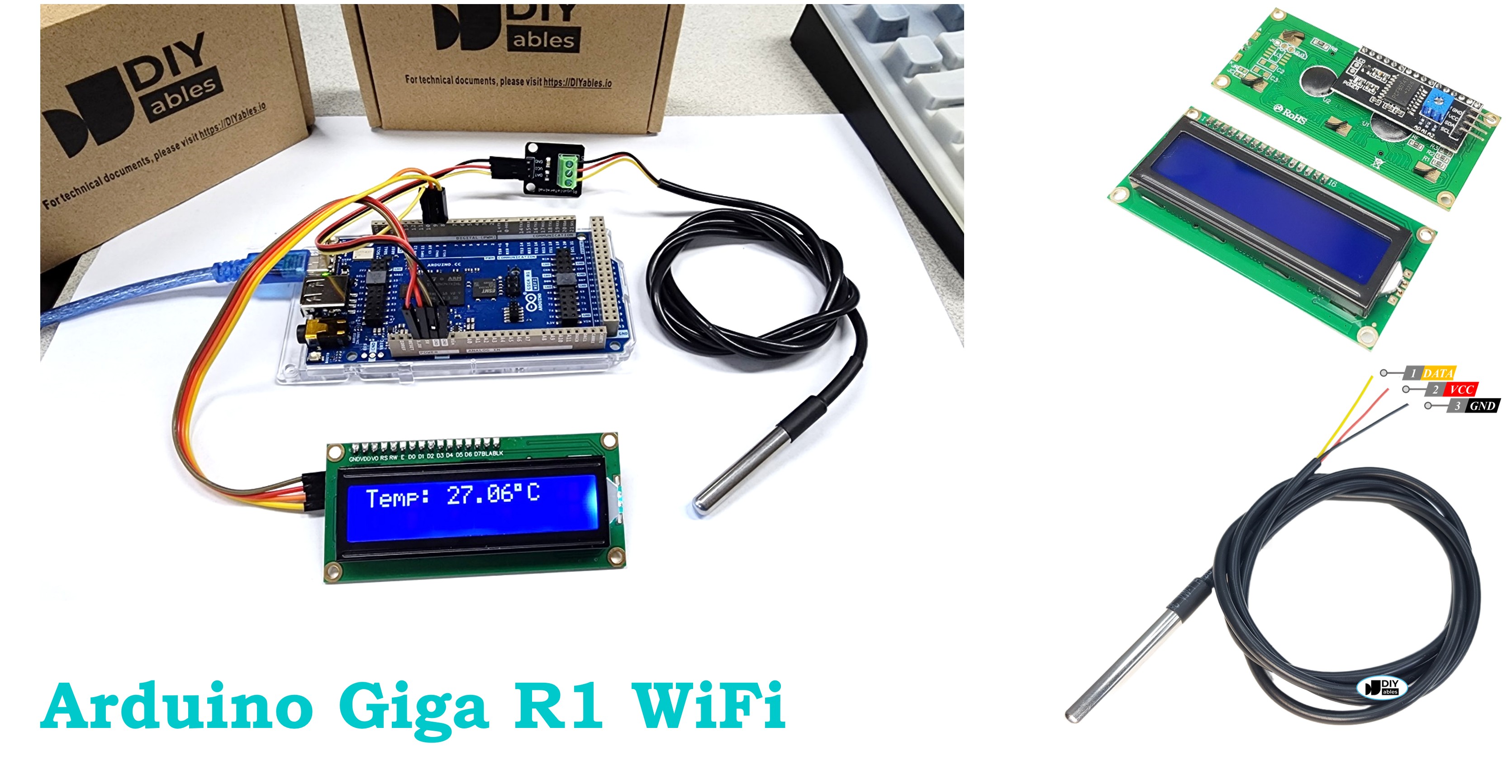
Arduino Giga R1 WiFi Temperature Sensor LCD
This guide demonstrates how to interface a DS18B20 temperature sensor with an I2C LCD display using the Arduino Giga R1 WiFi. The DS18B20 provides accurate digital temperature readings using the OneWire protocol, while the I2C LCD offers a user-friendly display with minimal wiring.
This tutorial covers sensor integration, LCD configuration, library installation, and code implementation. You'll build a complete temperature monitoring system that continuously reads sensor data and displays it on a 16x2 LCD with proper formatting.
Hardware Preparation
Or you can buy the following kits:
| 1 | × | DIYables Sensor Kit (18 sensors/displays) |
Additionally, some of these links are for products from our own brand, DIYables .
Buy Note: Many DS18B20 sensors available in the market are unreliable. We strongly recommend buying the sensor from the DIYables brand using the link provided above. We tested it, and it worked reliably.
Buy Note: Alternatively, you can assemble the LCD I2C display using LCD 1602 Display and PCF8574 I2C Adapter Module.
Overview of Temperature Sensor and LCD
The DS18B20 is a digital temperature sensor that measures -55°C to +125°C with ±0.5°C accuracy. It operates on the OneWire protocol, outputting 12-bit resolution data (0.0625°C increments). The sensor requires a 4.7kΩ pull-up resistor on the data line, though sensors with adapter boards include this resistor. Conversion time is 750ms for 12-bit resolution.
The I2C LCD uses a PCF8574 I/O expander to reduce the pin count from 6+ pins to just two I2C lines (SDA and SCL). The standard 16x2 character LCD provides adequate space for displaying temperature readings with units and labels.
If you do not know about temperature sensor and LCD (pinout, how it works, how to program ...), learn about them in the following tutorials:
Wiring Diagram
The wiring diagram demonstrates the integration of both DS18B20 and I2C LCD with the Arduino Giga R1 WiFi, utilizing the OneWire protocol for temperature sensing and I2C for display communication. This configuration minimizes pin usage while maximizing functionality.
Electrical Note: The diagram above shows the minimum viable connection for prototyping. For production or extended use, consider adding 100nF ceramic capacitors near each device's power pins to improve noise immunity and signal integrity. The DS18B20's OneWire line should be kept as short as practical (under 20cm for single sensors) to maintain reliable communication.
| DS18B20 Pin | Arduino Giga R1 WiFi Pin | Function |
|---|---|---|
| VCC (Red) | 5V | Power supply (3.3V-5V compatible) |
| GND (Black) | GND | Ground reference |
| DATA (Yellow) | Pin 2 | OneWire data line with 4.7kΩ pull-up |
| LCD I2C Pin | Arduino Giga R1 WiFi Pin | Function |
|---|---|---|
| VCC | 5V | Power supply (5V for backlight operation) |
| GND | GND | Ground reference |
| SDA | SDA2 (Pin 9) | I2C data line |
| SCL | SCL2 (Pin 8) | I2C clock line |
- Wiring diagram
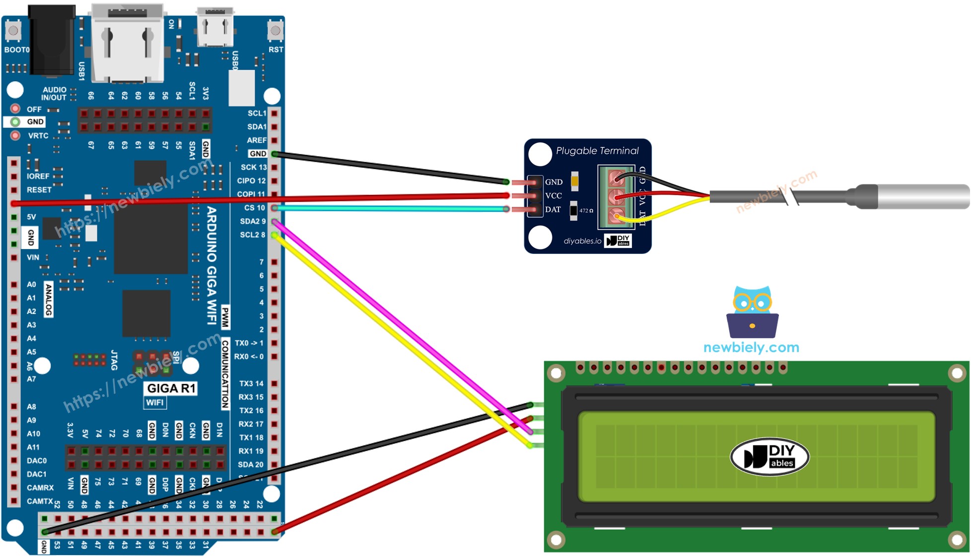
This image is created using Fritzing. Click to enlarge image
- Real wiring
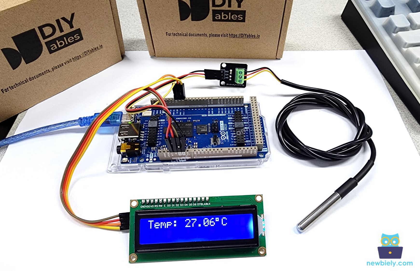
We suggest purchasing a DS18B20 sensor that comes with a wiring adapter for easy connection. The adapter has a built-in resistor, eliminating the need for a separate one in the wiring.
Arduino Code
The following implementation demonstrates a combined sensor reading and display system using interrupt-driven timing for smooth temperature updates. The code is structured to handle both OneWire sensor communication and I2C display formatting efficiently. Key sections include sensor initialization, temperature conversion with error handling, and formatted display output with proper decimal precision.
The implementation utilizes the DallasTemperature library to abstract OneWire protocol complexity and the DIYables_LCD_I2C library for simplified display control. Both libraries are well-optimized for the Arduino Giga R1 WiFi's architecture and provide robust error handling for production applications. The code includes temperature validation to handle sensor disconnection or communication errors gracefully.
※ NOTE THAT:
The I2C address of LCD can vary according to the manufacturers. In the code, we used 0x27 that is specified by DIYables manufacturer
Detailed Instructions
Prerequisites: Arduino IDE installed and the Giga R1 WiFi board package configured. Refer to the Getting Started guide for setup instructions.
- Connect Hardware: Wire the DS18B20 temperature sensor to pin 2 (OneWire data) and the I2C LCD to SDA2/SCL2 pins as shown in the wiring diagram. Verify all power and ground connections are secure and match the voltage requirements (5V for LCD backlight operation).
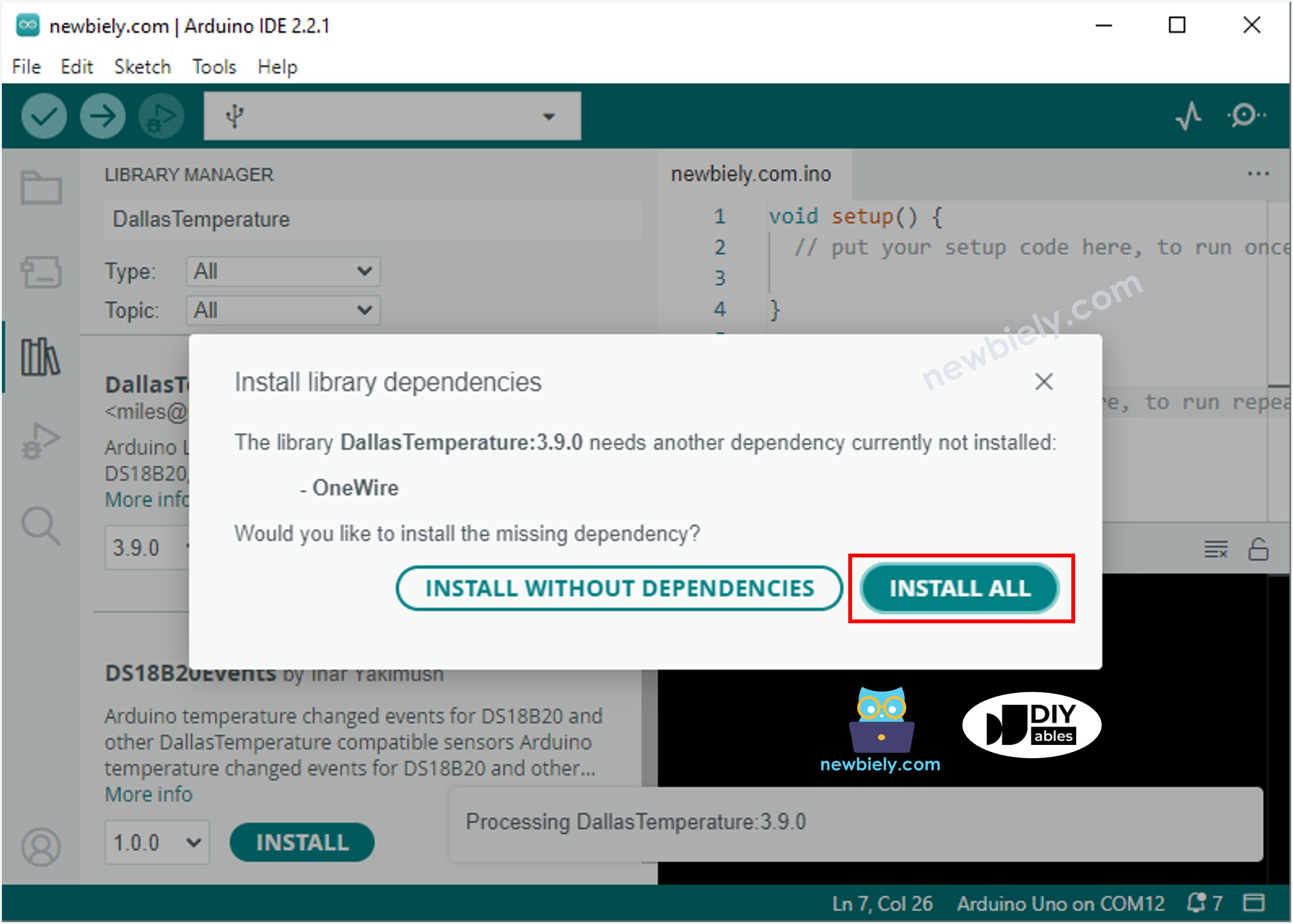
- Install DallasTemperature Library: Navigate to the Libraries icon on the left bar of the Arduino IDE. Search "DallasTemperature", then find the DallasTemperature library by Miles Burton. Click Install button. This library handles OneWire protocol communication and temperature conversion algorithms.
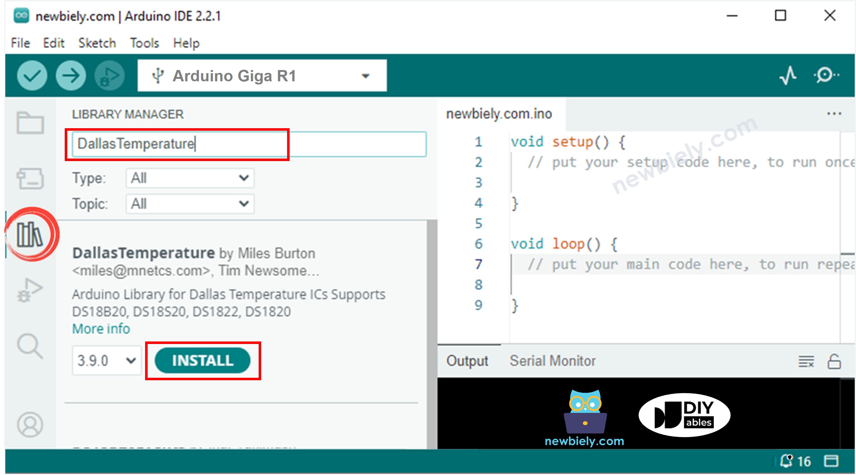
- Install Dependencies: You will be prompted to install the OneWire library dependency. Click Install All button to install OneWire library. This provides the low-level OneWire protocol implementation required by the DallasTemperature library.
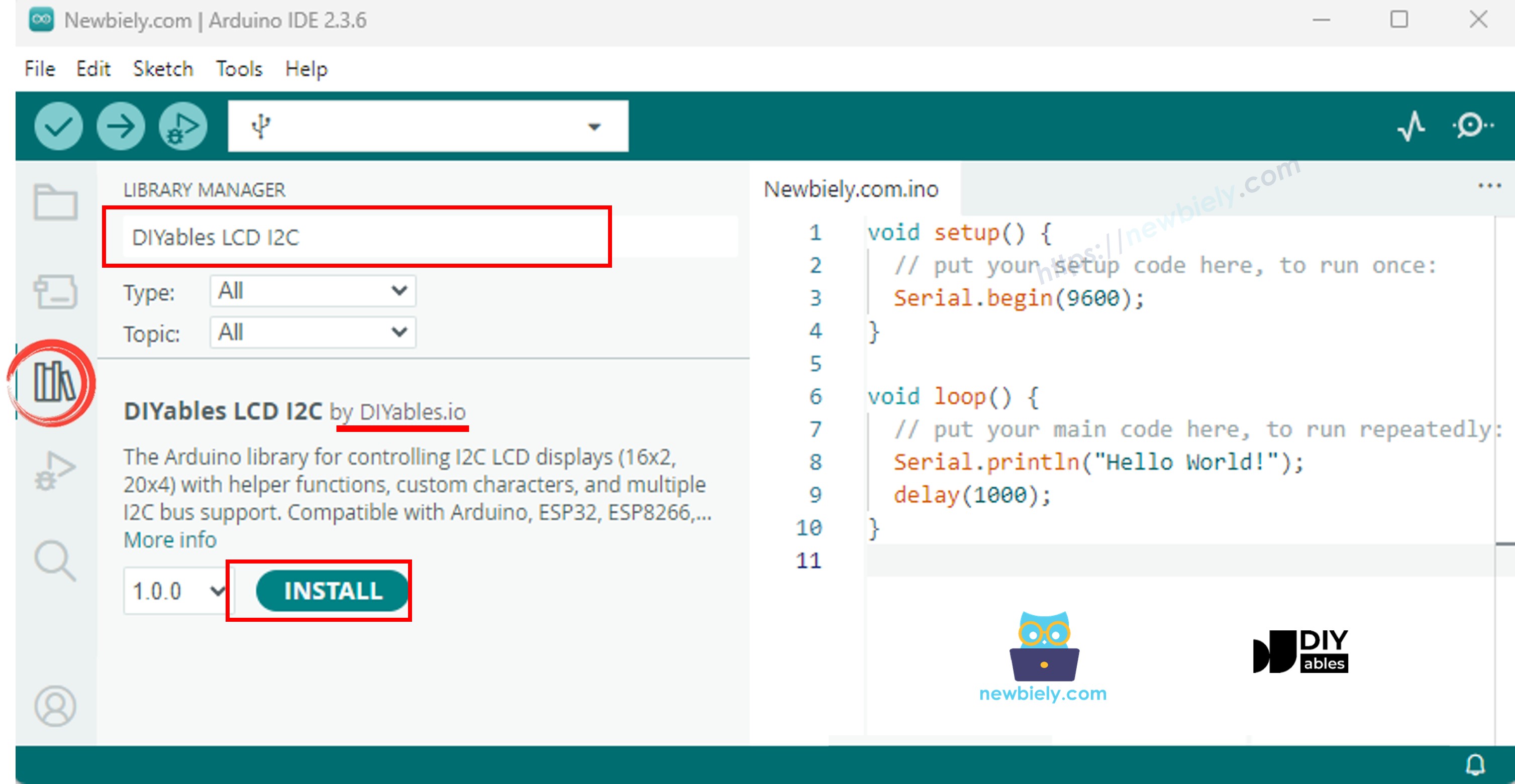
- Install LCD Library: Search "DIYables LCD I2C", then find the DIYables_LCD_I2C library by DIYables. Click Install button. This library simplifies I2C LCD control and handles character display formatting automatically.
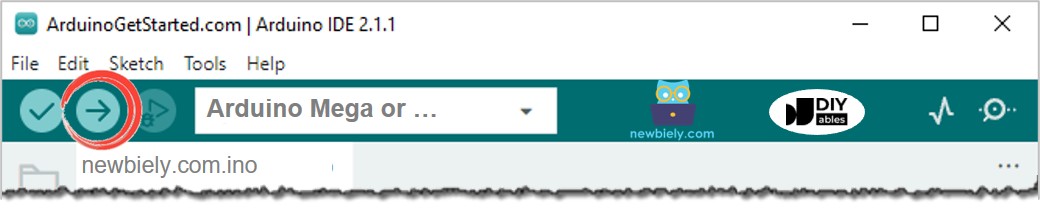
- Upload Code: Copy the provided code and open with Arduino IDE. Select the correct board (Arduino Giga R1 WiFi) and COM port, then click Upload button. The code will compile and transfer to the Arduino automatically.
- Test Operation: Place the DS18B20 sensor in different temperature environments (room temperature, warm water, cold water, or grasp with your hand). The LCD should display temperature readings that update approximately every 1-2 seconds with smooth transitions.
- Verify Display: The LCD should show "Temperature: XX.XX°C" format on the first line with numeric values updating based on sensor readings. If the LCD displays nothing or shows garbled characters, verify I2C connections and check the troubleshooting section below.
- Calibration Check: Compare displayed readings with a known reference thermometer. The DS18B20 should be accurate to ±0.5°C in normal room temperature ranges. Significant deviations may indicate wiring issues or sensor damage.
Technical Note: The system updates temperature readings every 750ms due to the DS18B20's 12-bit conversion time. For faster updates, consider reducing resolution to 9-bit (0.5°C precision, 93ms conversion) using the setResolution() function. The Arduino Giga R1 WiFi's dual-core capability allows for implementing display updates on one core while maintaining sensor polling on the other for ultra-smooth operation.
If LCD displays nothing, see Troubleshooting on LCD I2C
Serial Monitor Output
Code Explanation
Read the line-by-line explanation in comment lines of source code!
Application Ideas
Environmental Monitoring Station: Implement a multi-sensor system that logs temperature data to the Arduino Giga R1 WiFi's onboard storage while displaying current readings on LCD. The dual-core processor enables simultaneous data logging and display updates without performance degradation.
HVAC Control Interface: Create a thermostat controller that compares DS18B20 readings against setpoints and controls heating/cooling systems via relay outputs. The Arduino Giga R1 WiFi's multiple timer peripherals enable precise temperature control algorithms with proportional-integral-derivative (PID) implementation.
Industrial Process Monitor: Deploy multiple DS18B20 sensors on different OneWire addresses to monitor temperature at various process points, displaying readings sequentially on the LCD. The Arduino Giga R1 WiFi's generous memory supports up to 100+ sensors on a single bus with individual calibration data.
Data Logger with WiFi Transmission: Combine temperature sensing with the Arduino Giga R1 WiFi's wireless capabilities to transmit readings to cloud services while maintaining local LCD display. Implement automatic data buffering during connectivity interruptions using the extensive RAM resources.
Greenhouse Automation System: Integrate temperature monitoring with environmental controls, using the LCD for local status display and the Arduino Giga R1 WiFi's connectivity for remote monitoring via web interface or mobile application.
Laboratory Temperature Recorder: Create a precision measurement system with timestamp logging, statistical analysis (min/max/average calculations), and alarm notifications when temperature exceeds defined thresholds. The Arduino Giga R1 WiFi's processing power enables real-time statistical computations without impacting sensor sampling rates.
Challenge Yourself
Challenge: Implement temperature trend indication by adding arrow symbols (↑↓) to show whether temperature is rising, falling, or stable compared to the previous reading.
Challenge: Add multiple DS18B20 sensors with unique addresses and cycle through their readings on the LCD display every 3 seconds. Use the Arduino Giga R1 WiFi's timer interrupts for precise timing control.
Challenge: Create a temperature alarm system that activates a buzzer when readings exceed user-defined thresholds. Store threshold values in EEPROM and provide button-based configuration interface.
Challenge: Implement a web server using the Arduino Giga R1 WiFi's connectivity to serve real-time temperature data as JSON API endpoints while maintaining LCD display functionality.
Challenge: Design a temperature data logger that stores readings with timestamps to an SD card, calculates daily/weekly temperature statistics, and displays historical data on the LCD using navigation buttons. Utilize the Arduino Giga R1 WiFi's RTC functionality for accurate timestamping.