Arduino Giga R1 WiFi Control Fan
This guide covers DC fan control with the Arduino Giga R1 WiFi using relay-based switching. The implementation uses relay switching to provide electrical isolation between the Arduino's low-voltage digital signals and the fan's power circuit.
This tutorial walks through relay interfacing, safety considerations for motor control, and working code examples. You'll implement a basic on/off fan controller suitable for temperature-responsive cooling systems or automated thermal management.
Hardware Preparation
Or you can buy the following kits:
| 1 | × | DIYables Sensor Kit (18 sensors/displays) |
Additionally, some of these links are for products from our own brand, DIYables .
Overview of DC Fan
DC fans convert DC electrical energy into rotational mechanical energy for forced air circulation. Operating voltages are typically 5V, 12V, or 24V DC, with current consumption from 50mA to 2A depending on size. Rotational speeds range from 1000 to 6000 RPM.
DC fans require relay interfacing for safe power switching, as direct GPIO drive cannot handle fan current demands. The Arduino Giga R1 WiFi's 3.3V logic levels work with relay modules for electrical isolation and current handling.
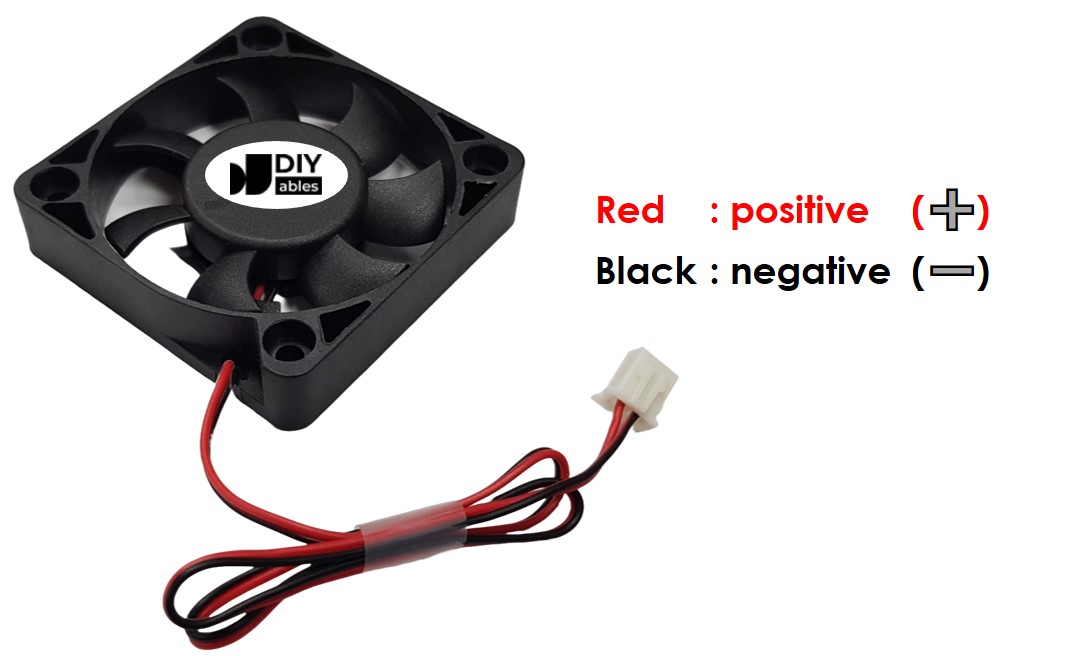
Pinout
The pinout defines the electrical interface between the fan motor and external power supply. Correct polarity connection is essential — reversed polarity may damage the internal motor controller in brushless fans or cause reverse rotation in brushed variants.
Negative (-) pin (black): DC return connection, 0V reference. Connects to the negative terminal of the DC power supply and system ground. Current capacity must match fan specifications — typically 100mA to 2A depending on fan size and speed rating.
Positive (+) pin (red): DC supply connection, rated voltage input. Connects to the positive terminal of the DC power supply through switching circuitry. Voltage tolerance is typically ±10% of rated voltage. Exceeding voltage specifications may cause overspeed conditions and premature bearing failure.
The fan operates on DC voltage matching its specification rating — 5V, 12V, or 24V are common variants. Voltage regulation within ±5% ensures optimal performance and longevity. Some advanced fans include additional pins for tachometer feedback (speed sensing) and PWM input (speed control), but basic cooling fans use the two-wire interface shown above.
Common wiring errors include reversed polarity (may damage brushless controllers), insufficient wire gauge for current capacity (causes voltage drop and overheating), and missing flyback protection (can damage switching components). The Arduino Giga R1 WiFi's 3.3V GPIO outputs cannot directly drive fan loads — relay interfacing provides the necessary isolation and current capacity.
How to Control Fan
DC fan control methods depend on the application requirements and desired performance characteristics. For simple on/off operation, relay switching provides complete electrical isolation and handles the full fan current without Arduino GPIO stress. For variable speed control, PWM drive circuits can modulate effective voltage to achieve proportional speed regulation.
Relay-Based Switching: When the relay coil is energized by the Arduino Giga R1 WiFi's digital output, the relay contacts close, connecting the fan to its DC power supply. The fan operates at full speed determined by the supply voltage. When the relay de-energizes, the contacts open, disconnecting power and stopping the fan. This method provides complete on/off control with electrical isolation.
PWM Speed Control: For variable speed operation, PWM signals can drive power MOSFETs or dedicated motor driver ICs to control effective voltage applied to the fan. Duty cycle modulation from 0-100% provides proportional speed control from stop to full speed. This advanced technique requires additional driver circuitry and will be covered in subsequent Arduino Giga R1 WiFi fan speed control tutorials.
The relay approach demonstrated in this tutorial offers several advantages: complete electrical isolation protects the Arduino from motor transients, full current capacity eliminates GPIO limitations, and reliable switching for continuous operation. Relay switching introduces minimal delay (typically 5-10ms) but provides robust operation for automation and thermal management applications.
To turn on/off a fan using the Arduino Giga R1 WiFi, relay interfacing is essential for safe operation. The Arduino controls the relay coil through a digital output pin, while the relay contacts switch the fan's power circuit. If you need detailed relay information including pinout specifications, operating principles, and programming techniques, refer to the comprehensive Arduino - Relay tutorial for complete implementation guidance.
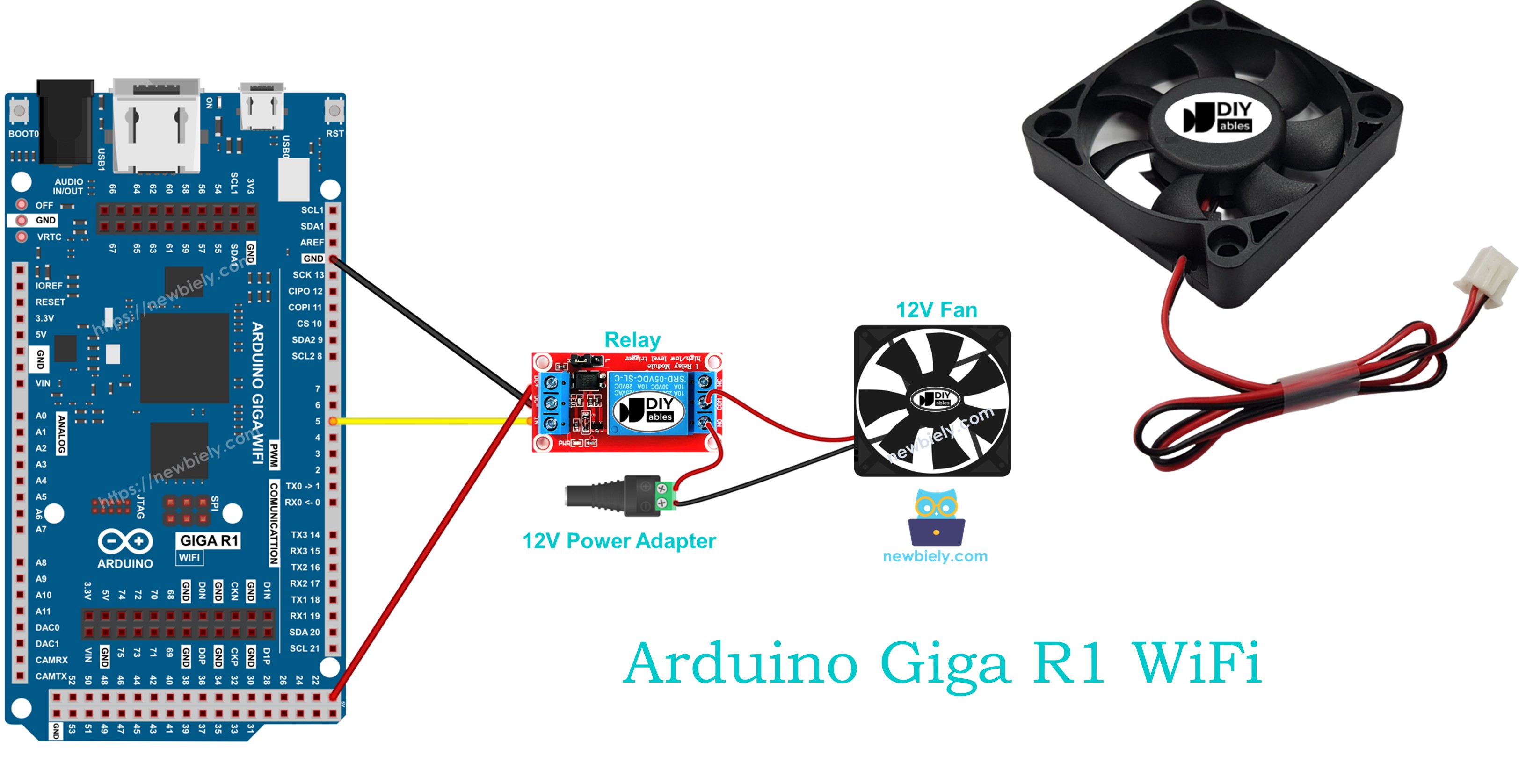
Wiring Diagram
The wiring diagram demonstrates the complete electrical connection between the Arduino Giga R1 WiFi, relay module, and DC cooling fan. This configuration provides safe electrical isolation while enabling full digital control of fan operation through relay switching.
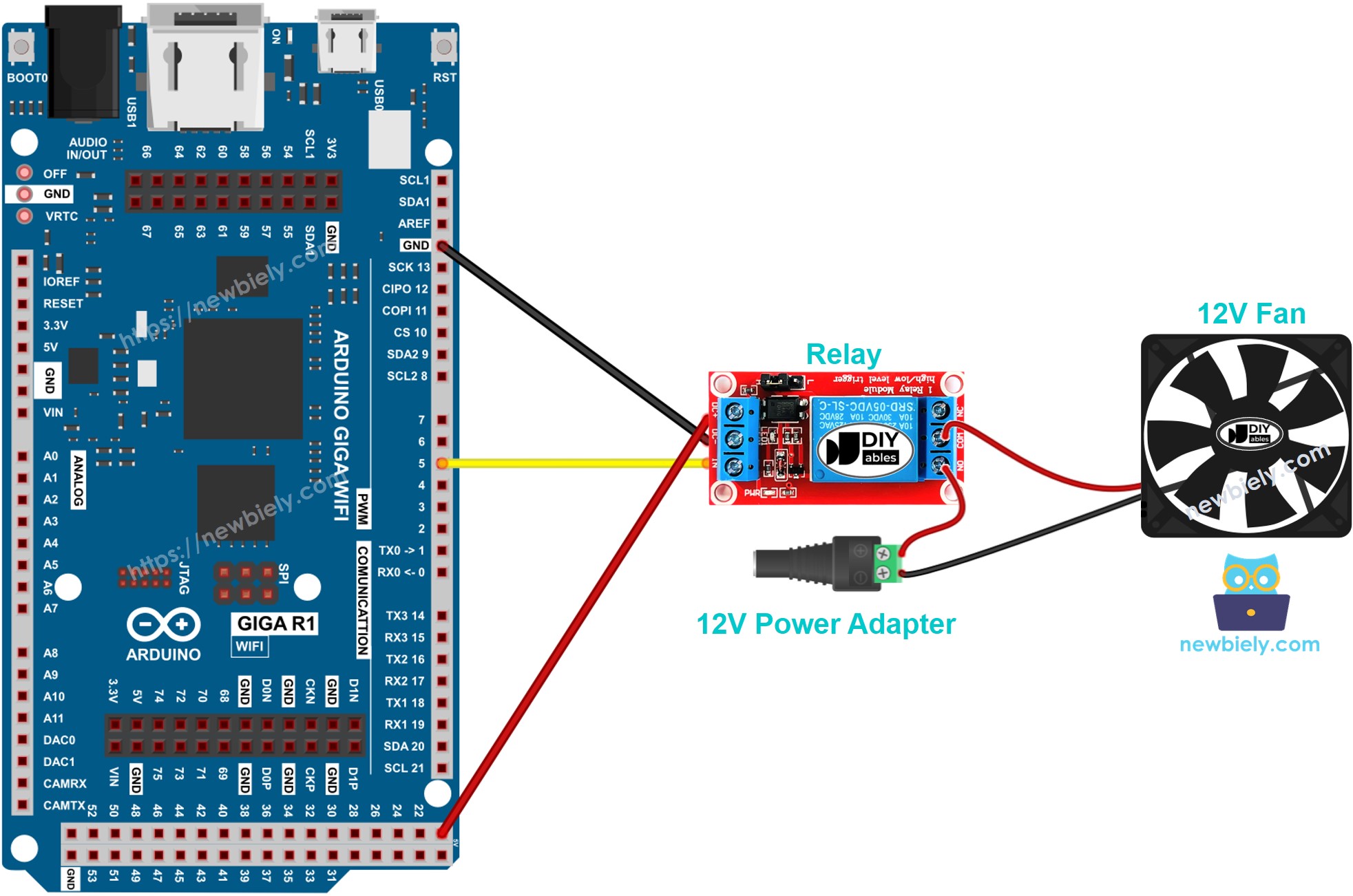
This image is created using Fritzing. Click to enlarge image
Electrical Note: The diagram above shows the minimum viable connection for Arduino Giga R1 WiFi fan control. For production or extended use, consider adding a flyback diode across the relay coil to suppress inductive kickback, and ensure adequate wire gauge for the fan current rating. The relay contacts should be rated for at least 125% of the fan's maximum current draw to prevent contact degradation over time.
Power supply considerations include maintaining voltage regulation within ±5% of the fan's rated voltage for optimal performance. Current consumption varies with fan size — typically 100-500mA for 12V desktop cooling fans. The Arduino Giga R1 WiFi's 3.3V digital outputs provide sufficient current (typically 8mA) to drive standard relay modules with built-in base resistors and transistor drivers.
| Component Pin | Arduino Giga R1 WiFi Pin | Function |
|---|---|---|
| Relay VCC | 5V | Relay module power supply |
| Relay GND | GND | Common ground reference |
| Relay IN | Digital Pin 7 | Relay control signal |
| Fan Positive | Relay NO Common | Switched DC power supply positive |
| Fan Negative | Power Supply GND | DC power supply return |
| Power Supply Positive | Relay NO | External DC supply input |
| Power Supply Negative | GND | Common ground reference |
Arduino Code
The following implementation demonstrates relay-based fan control using digital output switching. The code is structured to handle timed on/off operation with clear state indication through the serial monitor. Key sections include relay initialization, timing control, and status feedback for debugging and monitoring.
The implementation uses Arduino's built-in digitalWrite() function to control the relay state, which in turn switches the fan power circuit. The delay() function provides timing intervals, though more advanced applications might use millis() for non-blocking timing that allows concurrent sensor monitoring or communication tasks. The serial output enables real-time monitoring of fan state changes.
Each code section is explained with inline comments to clarify the relay control logic, timing sequences, and expected hardware behavior. The digitalWrite(HIGH) command energizes the relay coil, closing the contacts and powering the fan, while digitalWrite(LOW) de-energizes the relay, opening the contacts and stopping the fan operation.
The below code repeatedly turns the fan ON for five seconds and OFF for five seconds, demonstrating basic timed cooling operation suitable for applications like intermittent ventilation or thermal cycling tests:
Detailed Instructions
Prerequisites: Arduino IDE installed and the Giga R1 WiFi board package configured. Refer to the Getting Started guide for setup instructions if needed.
- Connect Hardware: Wire the relay module, DC fan, and power supply according to the wiring diagram. Verify all connections match the pin assignments — relay control to digital pin 7, power supply polarity, and proper grounding. The relay should click audibly when the Arduino powers up if wiring is correct.
- Open Arduino IDE: Launch the Arduino IDE and select "Arduino Giga R1 WiFi" from the board menu. Ensure the correct COM port is selected under Tools > Port. The Arduino should appear as a recognized USB device when connected properly.
- Upload Code: Copy the provided code into a new Arduino sketch. Click the Upload button to compile and transfer the program to the Arduino Giga R1 WiFi. The IDE should report "Upload complete" without errors. If compilation fails, verify the board package is properly installed.
- Monitor Serial Output: Open the Serial Monitor (Tools > Serial Monitor) and set the baud rate to 9600. The monitor should display "Fan: ON" and "Fan: OFF" messages every five seconds, corresponding to the relay switching cycles. This confirms proper code execution and timing.
- Verify Fan Operation: Observe the physical fan behavior during each cycle. The fan should start spinning when "Fan: ON" appears and stop when "Fan: OFF" is displayed. The relay module LED (if present) should also indicate the switching state. If the fan doesn't respond, check power supply voltage and relay contact ratings.
- Test Relay Switching: Listen for the relay contact clicking sound during state changes. This confirms the Arduino Giga R1 WiFi is successfully controlling the relay coil. If no clicking occurs, verify the relay module wiring and the Arduino's 5V power output capability.
Technical Note: The 5-second timing intervals are implemented using blocking delay() functions, which halt all other Arduino processing during each delay period. For applications requiring concurrent sensor monitoring or communication, replace delay() with millis()-based non-blocking timing to maintain system responsiveness while controlling fan operation.
Code Explanation
Read the line-by-line explanation in comment lines of code!
Serial Monitor Output
Do more with fan
Application Ideas
Thermal Management System: Implement temperature-responsive cooling for electronics enclosures or server rooms. The Arduino Giga R1 WiFi's analog inputs can monitor temperature sensors, triggering fan operation when thermal thresholds are exceeded. The board's dual-core architecture enables simultaneous temperature monitoring and fan control with precise hysteresis implementation.
Automated Ventilation Controller: Create scheduled ventilation systems for greenhouses, tutorials, or storage areas. The Arduino Giga R1 WiFi's WiFi capability allows remote scheduling and monitoring, while multiple digital outputs can control several fan zones independently based on time schedules or environmental conditions.
Industrial Process Cooling: Deploy in manufacturing environments where equipment cooling follows production schedules. The Arduino Giga R1 WiFi's robust I/O can interface with industrial sensors and PLCs, providing integrated cooling control that scales with production demands and equipment thermal loads.
Data Logger Integration: Combine fan control with environmental data logging for HVAC performance analysis. The Arduino Giga R1 WiFi's expanded memory supports extensive data storage, while WiFi connectivity enables cloud-based monitoring and remote system diagnostics for predictive maintenance.
Smart Home Climate Control: Integrate with home automation systems for energy-efficient cooling. The Arduino Giga R1 WiFi can communicate with smart thermostats, occupancy sensors, and mobile apps to optimize fan operation based on room usage patterns and energy costs.
Laboratory Equipment Cooling: Control cooling fans for laboratory instruments that require precise thermal regulation. The Arduino Giga R1 WiFi's timing precision ensures accurate temperature cycling for analytical equipment, while serial communication provides integration with laboratory data acquisition systems.
Challenge Yourself
Challenge: Implement temperature-based fan control using a DHT22 sensor. Add hysteresis logic to prevent rapid on/off cycling around the threshold temperature, and include configurable temperature setpoints via serial commands.
Challenge: Create a multi-zone cooling system controlling three fans independently. Use different temperature sensors for each zone and implement priority-based cooling that activates the most critical zones first during high thermal load conditions.
Challenge: Add PWM speed control to create variable fan speed based on temperature differential. Replace the relay with a MOSFET driver circuit and implement proportional cooling that adjusts fan speed linearly with temperature above the baseline threshold.
Challenge: Develop a WiFi-enabled fan controller with web interface control. Use the Arduino Giga R1 WiFi's WiFi capabilities to create a web server that displays current fan status, allows remote on/off control, and provides historical runtime data for maintenance scheduling.
Challenge: Implement a smart cooling system that learns usage patterns and pre-emptively activates cooling based on predicted thermal loads. Store historical temperature and usage data in the Arduino's expanded memory, then use simple prediction algorithms to optimize cooling efficiency and energy consumption.