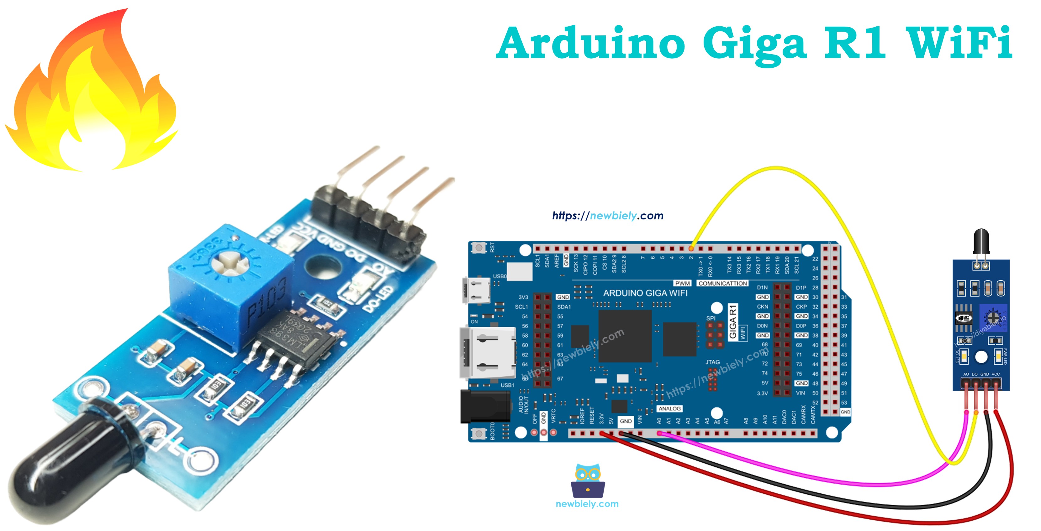
Arduino Giga R1 WiFi Flame Sensor
This guide covers infrared flame sensor integration with the Arduino Giga R1 WiFi. The flame sensor detects infrared radiation emitted from flames, providing both digital and analog output signals.
This tutorial demonstrates digital fire detection for binary flame presence detection, analog infrared level monitoring for flame intensity measurement, and practical implementation for real-world fire safety applications.
Afterward, you can modify the code to activate a warning horn (via a relay) when it detects fire.
Hardware Preparation
Or you can buy the following kits:
| 1 | × | DIYables Sensor Kit (18 sensors/displays) |
Additionally, some of these links are for products from our own brand, DIYables .
Overview of Flame Sensor
The infrared flame sensor detects specific wavelengths of infrared radiation (typically 760nm to 1100nm) characteristic of combustion. The sensor uses a photodiode or phototransistor responsive to the infrared spectrum emitted by flames.
The sensor provides both digital output (threshold detection) and analog output (intensity measurement). Operating voltage is 3.3V to 5V with detection range of 60cm to 100cm depending on flame size and response time under 15ms. The sensor is selective for flame signatures while rejecting false triggers from incandescent lighting and sunlight.
Pinout
Correct pinout understanding is critical for safe sensor integration. An incorrect connection may damage the sensor or produce unreliable readings due to incorrect signal levels or power supply issues.
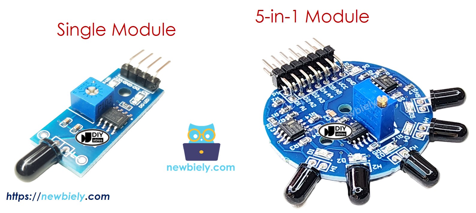
There are two types of flame sensor modules available:
A single flame sensor includes four pins with specific electrical characteristics:
- VCC pin: Power supply input, 3.3V to 5V DC. Typical current consumption 15mA. Connect to Arduino Giga R1 WiFi 5V or 3.3V output to provide sensor power.
- GND pin: Ground reference, 0V. Connect to Arduino GND to establish common electrical reference.
- DO pin: Digital output, TTL compatible (0V/5V logic levels). Output is HIGH (5V) when no flame detected, LOW (0V) when flame detected. Maximum output current 10mA. Connect to any Arduino digital input pin (D2-D53).
- AO pin: Analog output, 0V to VCC range. Output voltage proportional to infrared intensity. Connect to Arduino analog input pin (A0-A15) for intensity measurement.
The sensor requires pull-up resistors on digital outputs, which are provided internally. No external components are required for basic operation, though decoupling capacitors (0.1μF ceramic) near VCC can improve noise immunity in electrically noisy environments.
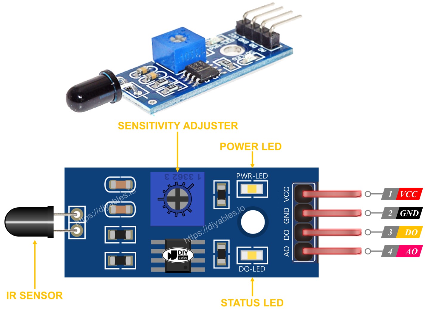
Furthermore, it has two LED indicators for operational status:
- PWR-LED indicator: Power status indicator. Illuminated when proper supply voltage applied to VCC pin.
- DO-LED indicator: Digital output status indicator. Illuminates when flame detected (DO pin LOW state).
The 5-in-1 flame sensor integrates five individual flame sensors on a single PCB, providing enhanced detection coverage and directional sensitivity. While they share the same potentiometer, VCC, and GND connections, each sensor's DO (Digital Output) and AI (Analog Input) pins function independently with separate signal processing circuits. Additionally, each sensor is oriented in a different direction, which effectively broadens the overall detection range to approximately 180 degrees of coverage compared to the single sensor's 60-degree detection cone.
How It Works
The flame sensor operates using infrared photodiode detection combined with analog signal processing and digital threshold comparison circuits.
For the DO pin (Digital Output):
- The module has a built-in potentiometer for setting the infrared threshold (sensitivity adjustment from approximately 10% to 90% of full scale).
- When the infrared intensity exceeds the threshold value, flame is detected, the digital output pin transitions to LOW (0V), and the DO-LED indicator illuminates.
- When the infrared intensity falls below the threshold value, flame is NOT detected, the digital output pin transitions to HIGH (5V), and the DO-LED indicator turns off.
- The comparator circuit includes hysteresis (approximately 50mV) to prevent output oscillation near the threshold point.
For the AO pin (Analog Output):
- The analog output provides continuous measurement of infrared intensity from 0V (no infrared) to VCC (maximum detectable intensity).
- Higher infrared intensity in the surrounding environment produces higher voltage on the AO pin (linear relationship within sensor's dynamic range).
- Lower infrared intensity in the surrounding environment produces lower voltage on the AO pin.
- The analog output has approximately 10-bit resolution equivalent when used with Arduino's ADC, providing 1024 discrete levels of intensity measurement.
Note that the potentiometer adjustment only affects the digital threshold comparison and does not influence the analog output voltage range or sensitivity.
Wiring Diagram
The wiring configuration depends on whether digital detection, analog measurement, or both outputs are required for the application. Proper connections ensure reliable signal transmission and prevent damage to both sensor and Arduino.
Since the flame sensor module has two outputs, you can choose to use one or both of them, depending on what you need.
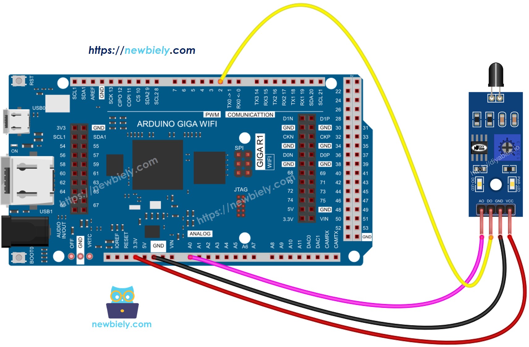
This image is created using Fritzing. Click to enlarge image
| Flame Sensor Pin | Arduino Giga R1 WiFi Pin |
|---|---|
| VCC | 5V |
| GND | GND |
| DO | Digital Pin 7 |
| AO | Analog Pin A0 |
Power supply requirements: The sensor draws 15mA typical current, well within the Arduino Giga R1 WiFi's 500mA 5V rail capacity. The sensor operates reliably from 3.3V to 5V, but 5V operation provides maximum sensitivity and detection range.
Arduino Code - Read value from DO pin
The following implementation demonstrates digital flame detection using threshold-based binary output. This approach provides simple fire/no-fire status suitable for alarm systems and automated responses. The code continuously polls the digital output and provides immediate detection feedback via serial communication.
The digital detection method uses the sensor's built-in comparator circuit with adjustable threshold sensitivity. This configuration is ideal for applications requiring fast response times and definitive flame presence detection without requiring intensity measurement.
Detailed Instructions
For initial Arduino Giga R1 WiFi setup, refer to the Arduino Giga R1 WiFi Getting Started guide before proceeding.
- Connect the Hardware: Wire the flame sensor to the Arduino Giga R1 WiFi according to the digital output wiring diagram. Ensure VCC connects to 5V, GND to GND, and DO to digital pin 7.
- Install Arduino IDE: Open the Arduino IDE and configure it for the Giga R1 WiFi board. Select "Arduino Giga" from the board manager if not already configured.
- Copy and Upload Code: Copy the provided code into a new Arduino sketch. Compile and upload to the Arduino Giga R1 WiFi. Verify successful upload completion.
- Open Serial Monitor: Set the serial monitor to 9600 baud rate to observe flame detection status. The monitor will display real-time detection results.
- Test Detection: Direct the flame sensor toward a flame source (candle, lighter, match). Observe the digital output status change and DO-LED indicator illumination.
- Adjust Sensitivity: If the sensor doesn't respond appropriately, adjust the onboard potentiometer clockwise to increase sensitivity or counterclockwise to decrease sensitivity until reliable detection occurs.
- Verify Operation: Confirm the serial output shows "flame is present" when detecting fire and "flame is NOT present" when no flame is detected. The response should be immediate (under 15ms).
Technical Note: The digital detection threshold can be fine-tuned using the potentiometer for different flame sizes and detection distances. Clockwise rotation increases sensitivity (detects smaller or more distant flames), while counterclockwise rotation decreases sensitivity (reduces false positives from ambient infrared sources).
Serial Monitor Output
Please keep in mind that if you notice the LED status remaining on constantly or off even when the sensor faces a flame, you can adjust the potentiometer to fine-tune the sensitivity of the sensor.
Arduino Code - Read value from AO pin
The analog implementation provides continuous infrared intensity measurement, enabling flame size estimation, distance calculation, and advanced fire monitoring applications. This approach outputs numerical values from 0-1023 (10-bit ADC resolution) corresponding to infrared intensity levels detected by the sensor.
Analog measurement is particularly useful for applications requiring flame intensity monitoring, multiple flame detection, or systems that need to differentiate between various infrared sources based on intensity levels.
Detailed Instructions
For initial Arduino Giga R1 WiFi setup, refer to the Arduino Giga R1 WiFi Getting Started guide before proceeding.
- Wire for Analog Output: Connect the flame sensor using the analog output wiring configuration. Ensure AO pin connects to analog pin A0 on the Arduino Giga R1 WiFi.
- Upload Analog Code: Copy the analog reading code and upload it to the Arduino Giga R1 WiFi. The code configures A0 as analog input and reads 10-bit ADC values.
- Open Serial Monitor: Set serial monitor to 9600 baud to observe continuous analog readings. Values will update continuously showing infrared intensity levels.
- Test Flame Response: Direct the sensor toward flames of different intensities. Observe how analog values increase with stronger flames and decrease with weaker or more distant flames.
- Record Baseline Values: Note the ambient infrared reading (typically 50-200) when no flame is present. This establishes the baseline for flame detection algorithms.
- Verify Dynamic Range: Test with various flame sources to understand the sensor's full analog range. Typical values range from 200-1000 depending on flame intensity and distance.
Technical Note: The analog output is not affected by the potentiometer setting and provides the full dynamic range of the sensor's infrared detection capability. For production applications, consider implementing moving average filtering to reduce noise and improve measurement stability.
Serial Monitor Output
Project Ideas
Industrial Fire Safety System: Implement a multi-zone fire detection network using multiple flame sensors connected to the Arduino Giga R1 WiFi's digital inputs. The dual-core processor enables simultaneous monitoring of up to 20 sensors while the WiFi capability provides real-time alerts to facility management systems and emergency services.
Smart Home Fire Detection: Create an IoT-based fire monitoring system that integrates with home automation platforms. The Arduino Giga R1 WiFi's wireless connectivity enables smartphone notifications, automatic sprinkler activation, and emergency service alerts when flames are detected in critical areas like kitchens or tutorials.
Gas Appliance Monitoring: Develop a flame monitoring system for gas water heaters, furnaces, or industrial burners. The analog output capability allows monitoring of flame stability and intensity, while the digital output can trigger safety shutoffs if flame failure is detected.
Laboratory Safety Monitor: Build a comprehensive laboratory safety system that monitors multiple fume hoods and experimental areas for flame or fire incidents. The Arduino Giga R1 WiFi's processing power enables data logging with timestamps, automated ventilation control, and integration with building management systems.
Welding Safety System: Create a specialized fire detection system for welding operations that can differentiate between normal welding arcs and actual fire emergencies. Use analog intensity thresholds and timing algorithms to reduce false alarms while maintaining safety responsiveness.
Data Logging Fire Monitor: Implement a fire detection system with SD card data logging capabilities. Record flame detection events with timestamps, intensity levels, and environmental conditions for fire safety analysis and compliance reporting.
Video Section
The accompanying video demonstrates the complete hardware assembly process and live code execution for both digital and analog flame detection modes. It covers proper sensor orientation for maximum detection range, potentiometer adjustment techniques for optimal sensitivity, and shows the expected serial monitor output patterns for various flame sources and distances.
Challenge Yourself
Challenge: Implement a multi-threshold flame detection system that classifies flame intensity into categories (small, medium, large) based on analog readings. Use LED indicators or buzzer patterns to indicate different threat levels.
Challenge: Create a flame position tracking system using multiple flame sensors arranged in a grid pattern. Calculate approximate flame location using triangulation algorithms and the Arduino Giga R1 WiFi's processing capabilities.
Challenge: Build a wireless flame detection network where multiple Arduino Giga R1 WiFi units with flame sensors communicate fire status to a central monitoring station. Implement mesh networking for redundant communication paths in large facilities.
Challenge: Develop a flame detection system with automatic fire suppression capability. Interface the flame sensor with relay modules to control water solenoids, CO2 systems, or alarm horns when fire is detected. Include manual override and system status monitoring.
Challenge: Implement a machine learning-based fire detection algorithm that learns normal infrared patterns and detects anomalies indicating fire conditions. Use the Arduino Giga R1 WiFi's expanded memory to store training data and classification models for improved accuracy and reduced false alarms.