Arduino Giga R1 WiFi Button LED
This guide covers button-controlled LED switching with the Arduino Giga R1 WiFi. The implementation demonstrates fundamental digital input/output concepts using push button control to directly manage LED state in real-time.
This tutorial walks through circuit design, proper current limiting, GPIO configuration, and polling-based input reading.
We are going to learn how to:
- Turn on LED if button is pressing.
- Turn off LED if button is NOT pressing.
We will learn how to toggle LED each time button is pressed in Arduino - Button Toggles LED tutorial.
Hardware Preparation
Or you can buy the following kits:
| 1 | × | DIYables Sensor Kit (18 sensors/displays) |
Additionally, some of these links are for products from our own brand, DIYables .
Buy Note: Use the LED Module for easier wiring. It includes an integrated resistor.
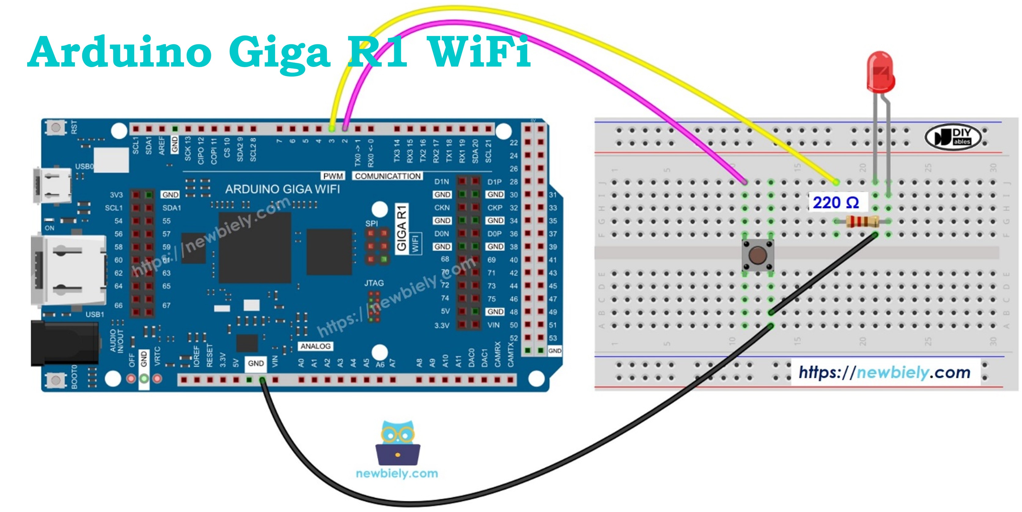
Wiring Diagram
The wiring diagram below demonstrates the essential connections for button-controlled LED operation. Proper component placement and current limiting are critical for reliable operation and component longevity.
This image is created using Fritzing. Click to enlarge image
Electrical Note: The diagram above shows the minimum viable connection. For production or extended use, consider adding a debouncing capacitor (100nF ceramic) across the button terminals to minimize contact bounce effects, and verify the LED forward current remains within specification under varying supply voltage conditions.
| Arduino Giga R1 WiFi Pin | Component Connection | Function |
|---|---|---|
| Digital Pin 2 | Button Terminal 1 | Digital input with internal pull-up |
| GND | Button Terminal 2 | Ground reference |
| Digital Pin 13 | LED Anode (via 220Ω resistor) | PWM-capable output, current-limited |
| GND | LED Cathode | Ground return path |
| 5V | Power rail (if external components need 5V) | Primary power supply |
The 220Ω current-limiting resistor prevents excessive current through the LED, maintaining forward current at approximately 18mA with a 5V supply. The button utilizes the Arduino's internal pull-up resistor, eliminating the need for external pull-up components while ensuring clean logic level transitions.
Arduino Code
The following implementation demonstrates direct GPIO polling for button state detection and immediate LED response. The code is structured to handle real-time input monitoring without delays that could affect responsiveness. Key sections include GPIO initialization, continuous state polling, and direct output control.
The standard Arduino digital I/O functions provide the necessary interface: pinMode() configures GPIO direction and pull-up behavior, digitalRead() samples the current input state, and digitalWrite() controls output levels. This polling-based approach ensures sub-millisecond response times for immediate visual feedback.
The implementation uses active-low button logic, where pressing the button pulls the input to ground (LOW state). The internal pull-up resistor maintains a HIGH state when the button is not pressed. LED control inverts this logic so the LED illuminates during button press events, providing intuitive user feedback.
Detailed Instructions
For initial Arduino Giga R1 WiFi setup, refer to the Arduino Giga R1 WiFi Getting Started guide before proceeding.
- Connect Components: Wire the button between digital pin 2 and ground, and connect the LED (with 220Ω resistor) between digital pin 13 and ground. Verify all connections match the wiring diagram exactly to prevent component damage.
- Launch Arduino IDE: Open the Arduino IDE and ensure the board is set to "Arduino Giga R1 WiFi" in the Tools menu. Select the correct COM port corresponding to your Arduino Giga R1 WiFi connection.
- Configure Code: Copy the provided code into a new Arduino IDE sketch. The code initializes pin 2 as an input with internal pull-up enabled and pin 13 as a digital output for LED control.
- Upload Firmware: Click the Upload button to compile and transfer the code to the Arduino Giga R1 WiFi. The IDE should display "Done uploading" upon successful completion without compilation errors.
- Test Operation: Press and hold the button while observing the LED. The LED should illuminate immediately when the button is pressed and turn off when released, demonstrating real-time button-to-LED control.
- Verify Serial Output: Open the Serial Monitor at 9600 baud to observe button state changes in real-time. The output should display current button status and corresponding LED state for debugging verification.
Technical Note: The polling loop executes continuously without delays, providing sub-millisecond response times. For applications requiring precise timing or multiple inputs, consider interrupt-driven button handling to improve system responsiveness and reduce CPU overhead.
Code Explanation
Read the line-by-line explanation in comment lines of source code! The implementation uses continuous polling to monitor button state changes and immediately update LED output accordingly. The digitalRead() function samples the button state each loop iteration, while digitalWrite() controls LED illumination based on the inverted button logic.
Serial Monitor Output
Application and Project Ideas
Industrial Control Panel: Implement emergency stop indicators and manual override controls in manufacturing systems. The Arduino Giga R1 WiFi's industrial-grade reliability enables integration with PLCs and SCADA systems for real-time status indication.
Interactive Prototype Interface: Create user interface mockups for product development and usability testing. Multiple button-LED pairs can simulate complex control systems, allowing rapid iteration of human-machine interface designs.
Security System Status Display: Build access control panels with button-activated status lights for door locks, alarm systems, and zone monitoring. The Giga R1 WiFi's WiFi capability enables remote status reporting and centralized monitoring.
Educational Training Platform: Develop hands-on learning tools for digital logic and embedded systems education. Students can explore cause-and-effect relationships in electronic systems while building foundational programming skills.
Home Automation Controller: Integrate manual override switches with smart home systems, providing physical backup controls for lighting and appliance management. The dual-core architecture supports simultaneous WiFi communication and local control processing.
Laboratory Equipment Interface: Create manual control systems for scientific instruments where immediate response and visual feedback are critical. The precise timing control ensures reliable operation in measurement and testing applications.
Video Tutorial
The accompanying video demonstrates the hardware assembly and live code execution. It covers proper component placement, wiring verification techniques, and shows the expected LED response during button press events on the serial monitor in real-time.
Challenge Yourself
Challenge: Implement multiple button-LED pairs on different GPIO pins to create a multi-channel control system with individual status indication for each input.
Challenge: Add button press duration measurement to distinguish between short presses and long holds, triggering different LED patterns based on press length using the millis() timing function.
Challenge: Create a WiFi-enabled remote monitoring system that logs button press events to a web server, combining local LED feedback with cloud-based activity tracking using the Arduino Giga R1 WiFi's networking capabilities.
Challenge: Implement interrupt-driven button handling using attachInterrupt() to improve system responsiveness and enable low-power operation modes while maintaining immediate LED response.
Challenge: Design a complete access control simulator with multiple buttons representing different user credentials, corresponding status LEDs, and serial communication protocol for integration with external security systems.