
Arduino MicroPython NTC Thermistor Temperature Sensor
Most temperature sensors keep their work hidden inside a chip and simply send you a number. The 10K NTC thermistor probe has no chip at all. Inside its steel tip there is only a tiny resistor, and its value goes down as it gets warmer. That makes it a great part for learning, because you can follow every step from a raw ADC number to a real temperature. Here, the Arduino Giga R1 WiFi runs MicroPython, and Thonny shows the results. You will find out:
- What the probe, its white 2-pin plug and the extra 10K resistor in the bag are for.
- How to connect it to three pins of the Giga: 3.3V, A0 and GND.
- How to average ten read_u16() readings and change them into ohms with one line of math.
- How math.log() and the beta formula turn those ohms into °C and °F, and what the script prints when a wire comes loose.
https://newbiely.com/images/cover/arduino-ntc-thermistor-temperature-sensor-micropython.jpg
Hardware Preparation
Or you can buy the following kits:
| 1 | × | DIYables Sensor Kit (18 sensors/displays) |
Additionally, some of these links are for products from our own brand, DIYables .
Overview of NTC Thermistor Temperature Sensor and Pinout
The probe looks like a small metal pen cap on a cable. The thermistor is sealed inside the stainless-steel tip, which is 5mm wide and 25mm long with a round end, so the tip can go into water. A black cable of 0.5m carries two wires to a white JST XH2.54 plug with two openings. No adapter board is needed: the metal pins of male jumper wires slide right into the plug.
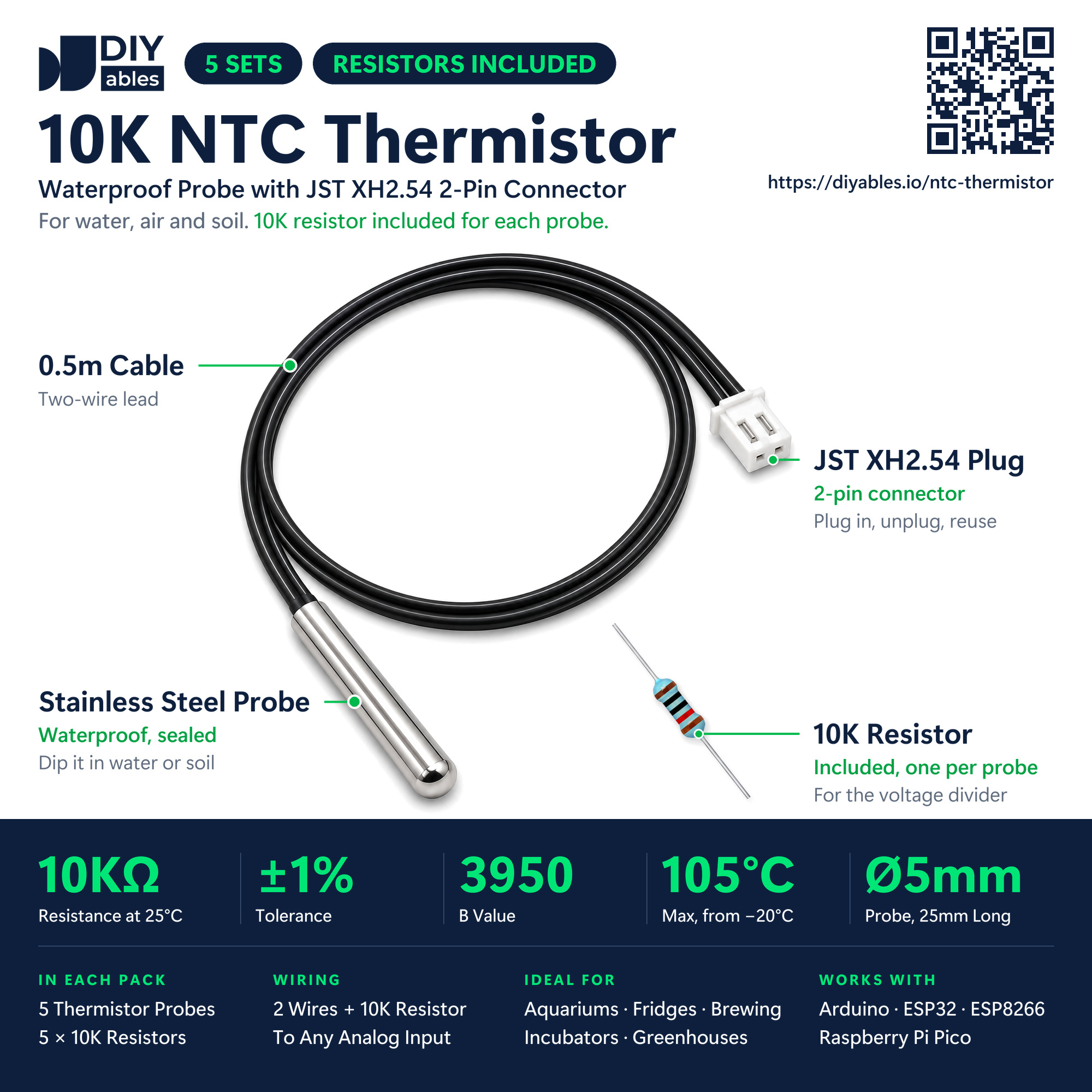
| Feature | Value |
|---|---|
| Sensor type | NTC thermistor, 10kΩ at 25°C (±1%) |
| B value | 3950 |
| Temperature range | -20°C to 105°C |
| Probe tip | stainless steel, waterproof, 5mm x 25mm |
| Cable | 0.5m, two wires |
| Connector | white JST XH2.54, 2 pins |
| Comes as | set of 5 probes, each with its own 10K resistor |
The two openings of the plug have no marks, and they do not need any. A thermistor is a resistor, so current can pass through it in both directions. Pick any wire and call it wire 1:
- Wire 1: the supply side. It goes to the 3.3V pin of the Giga.
- Wire 2: the signal side. It goes to pin A0, and the 10K resistor starts here too.
- 10K resistor: its other leg goes to GND. It is not built into the probe, but you get one in the same bag as every probe.
Why does a resistor need a second resistor? The ADC of the Giga can only measure a voltage, not ohms. The probe and the 10K resistor share the 3.3V between them. This pair is called a voltage divider. When the tip warms up, the thermistor resistance falls, its share of the voltage gets smaller, and the voltage on A0 goes up. When the tip cools down, A0 goes down. NTC means Negative Temperature Coefficient, which simply says: more heat, fewer ohms.
Here are some values for this exact circuit:
| Temperature | Thermistor | Voltage on A0 | read_u16() value |
|---|---|---|---|
| -15°C | about 77.9kΩ | 0.38V | 7456 |
| 5°C | about 25.9kΩ | 0.92V | 18242 |
| 23°C | about 10.9kΩ | 1.58V | 31303 |
| 40°C | about 5.3kΩ | 2.16V | 42829 |
| 85°C | about 1.09kΩ | 2.98V | 59112 |
From ohms to degrees
Look at the table again. From 5°C to 23°C, the resistance drops by about 15kΩ. From 40°C to 85°C, it drops by only about 4kΩ. The curve is not a straight line, so a simple multiply cannot give the temperature. The script uses the beta formula (also called the B-parameter equation):
1/T = 1/T0 + (1/B) × ln(R/R0)
- T: the temperature we want, in kelvin.
- T0: 298.15K, which is 25°C.
- R: the thermistor resistance that the script has just measured.
- R0: 10000Ω, the resistance of the probe at 25°C.
- B: 3950, the value from the probe's datasheet.
To get °C, take 273.15 away from T. You may also read about the Steinhart-Hart equation. It uses three numbers instead of one and is a little more exact, but for this probe the beta formula is fine. Near room temperature, expect the result to be within about 1°C. The real value of your 10K resistor and the ADC of the board decide most of that difference.
Wiring Diagram
Only three pins of the Giga are used. 3.3V and A0 are on the lower header. The drawing uses the GND pin at the right end of the board, but any GND pin of the Giga works the same.
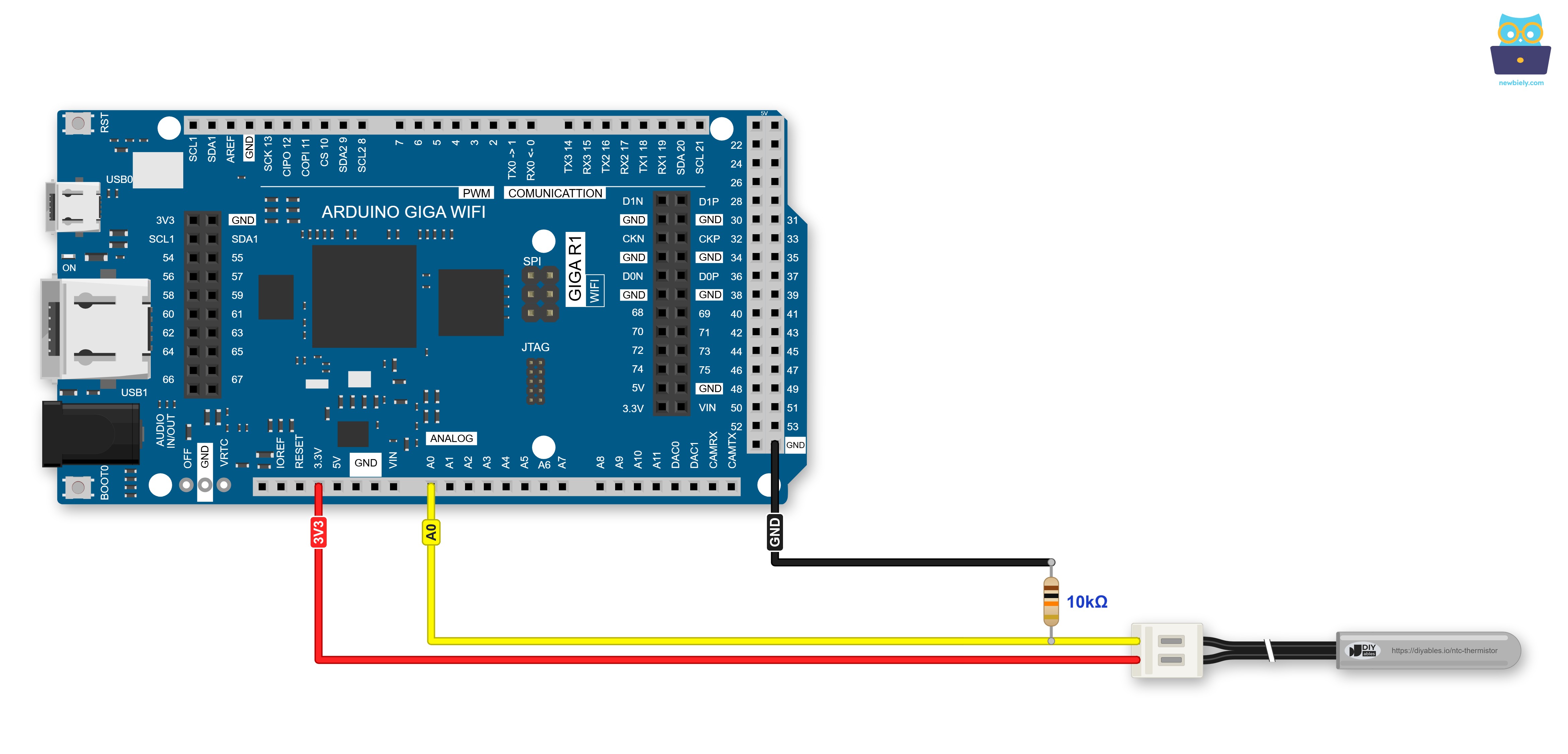
This image is created using Fritzing. Click to enlarge image
| NTC Probe Circuit | Arduino Giga R1 WiFi Pin |
|---|---|
| First probe wire (either one) | 3.3V |
| Second probe wire | A0 |
| 10K resistor, signal-side leg | A0 |
| 10K resistor, ground-side leg | GND |
In the picture, the resistor hangs between the yellow A0 wire and the black GND wire. To build this point for real, a small breadboard is the easy way. Put the jumper from the plug, the jumper to A0 and one resistor leg in the same row. Put the other resistor leg and the GND jumper in a second row. No breadboard? Wrap each resistor leg tightly around the metal pin of a jumper wire, or solder it, and cover the bare metal with tape.
※ NOTE THAT:
- The probe takes its power from 3.3V, and this choice helps twice. First, it keeps A0 safe. In a hot liquid, the thermistor drops to a few hundred ohms, and A0 climbs almost up to the supply voltage. A 5V supply would push A0 above what the analog pins of the Giga can take.
- Second, it keeps the reading right. read_u16() measures against the same 3.3V, so the script only needs the ratio raw ÷ 65535. If your USB port gives a slightly different voltage, the divider and the ADC move together, and the temperature does not change.
How To Program NTC Thermistor With MicroPython
Nothing to install. The machine module gives you the ADC, and the math module has the natural logarithm.
- Create an ADC object on A0, the pin between the probe and the 10K resistor:
- One read_u16() value moves up and down a little. Read ten times and keep the average:
- Work out the thermistor resistance. Only the ratio of the reading to 65535 is needed:
- Put the resistance into the beta formula. In MicroPython, math.log() with one argument is the natural log (ln):
- Check raw before the math. Close to 0 means only the 10K resistor holds A0, so the probe is unplugged. Close to 65535 means A0 is stuck at 3.3V. Without this check, the script would stop with a ZeroDivisionError or a "math domain error". With it, you get a short hint instead.
Quick wiring test: in the Thonny Shell, type the two lines below. At room temperature, the number should be somewhere around 30000 to 34000:
Arduino MicroPython Code - NTC Thermistor Temperature Sensor
This script prints one line per second, and each line shows the whole chain: the averaged A0 number, the thermistor resistance, and the temperature in °C and °F. When something looks wrong, you can see at which step it starts.
Detailed Instructions
To run the script on the Arduino Giga with Thonny IDE:
- Have Thonny IDE installed on your computer.
- Check that MicroPython firmware is already on your Arduino board.
- First time with Arduino and MicroPython? Read the Getting Started with Arduino and MicroPython guide.
- Build the circuit: one probe wire to 3.3V, the other probe wire to A0, and the 10K resistor from A0 to GND.
- Plug the Arduino Giga into your computer with the USB Type-C cable.
- In Thonny IDE, go to Tools Options.
- On the Interpreter tab, choose MicroPython (generic) in the dropdown menu.
- Select the COM port of your Arduino board (e.g., COM33 on Windows or /dev/ttyACM0 on Linux).
- Paste the script into Thonny's editor.
- Store the script on the Arduino:
- Click the Save button or press Ctrl+S.
- In the save dialog, choose MicroPython device and name the file main.py.
- Click the green Run button (or press F5).
- Let the probe lie on the desk for a few lines. Then set a hair dryer to its lowest heat, hold it about 30cm away, and blow warm air on the steel tip for about ten seconds. Switch the dryer off. A few seconds later, pull one jumper wire out of the white plug.
The first three lines show the room: about 23.4°C. The resistance is a bit above 10kΩ, because the room is a little cooler than 25°C. The warm air lifts the reading to 47.3°C, and the resistance falls below 4kΩ. After the dryer stops, the steel tip gives its heat back to the air more slowly, so the numbers go down more gently. A probe always needs a few seconds to follow a change, so wait until the value is steady before you trust it. The last two lines came after the jumper wire was pulled out: A0 fell to almost 0, and the script told us instead of crashing.
※ NOTE THAT:
Keep the hair dryer on low heat and not too close. Near the nozzle, the air is much hotter, and this probe must stay at 105°C or below.
Because the file is named main.py, the Giga runs it by itself each time it gets power. You do not need Thonny to start the thermometer again.
Project Ideas With the NTC Thermistor
Only the steel tip is waterproof. For a setup that stays in place, keep the white plug and the resistor joint dry and above the water. The cable can be made longer with extra wire, but keep it away from motor and mains wires, which can add noise to the reading. Some ideas:
- Fish tank watch: light a red LED when the water leaves the 24°C to 28°C band that most tropical fish like.
- Freezer alarm: feed the probe through the door seal and sound a buzzer if the freezer gets warmer than -15°C. The probe reads down to -20°C.
- Brewing helper: keep an eye on a fermentation bucket, and let a relay switch a heat pad on and off.
- Battery logger: tape the tip to a battery pack while it charges, and use open() to write one line per minute to a file on the Giga's own flash.
Want the temperature as ready-made digital data, with no resistor and no formula? The Arduino MicroPython Temperature Sensor tutorial uses the waterproof DS18B20 probe. For an oven or a grill, above 105°C, choose a thermocouple instead.