Arduino MKR WiFi 1010 - Button
Welcome to this comprehensive guide on using buttons with your Arduino MKR WiFi 1010! Buttons might seem straightforward—press to connect, release to disconnect—but their mechanical nature introduces challenges that trip up even experienced makers. This tutorial tackles those issues head-on, showing you proper wiring, clean code practices, and troubleshooting techniques.
What You'll Master:
- Understanding button mechanics and internal connections
- Solving the notorious "floating input" problem
- Proper use of pull-up and pull-down resistors
- Detecting button presses, releases, and state changes
- Recognizing and handling the chattering phenomenon
※ NOTE THAT:
Critical Beginner Pitfalls (Read This First!)
Before we dive into button basics, let's address two fundamental issues that cause 90% of button-related frustrations:
1. Floating Input Issue (Random Readings)
- What happens: You wire up a button, but readings bounce randomly between HIGH and LOW—even when you're not touching it. Your project behaves erratically.
- Why it happens: When the button is open (not pressed), the input pin is electrically "floating"—not connected to anything. It picks up electromagnetic interference from your environment like an antenna, causing random voltage readings.
- The fix: Always use a pull-up or pull-down resistor. These resistors "pull" the input to a known state (HIGH or LOW) when the button isn't pressed, ensuring predictable readings.
- Details: Covered thoroughly in sections below.
2. Chattering (Multiple False Triggers)
- What happens: You press the button once, but your Arduino registers 3-10 rapid presses. Counters increment wildly, and state machines go haywire.
- Why it happens: Button contacts don't close cleanly. For about 1-20 milliseconds during physical contact, the metal contacts bounce against each other, rapidly connecting and disconnecting. Your Arduino samples these bounces as separate press events.
- When it matters: Critical for counting button presses (click counter, game controller) or toggling states (ON/OFF switch simulation). Not a problem if you just want to know "is button currently held down?"
- The fix: Use software debouncing (code-based filtering) or hardware debouncing (capacitor circuit). See our dedicated Arduino MKR WiFi 1010 - Button Debounce tutorial.
Quick Rule: Every button project needs pull-up/pull-down resistors. Projects that count presses or detect edges also need debouncing.
Hardware Preparation
Or you can buy the following kits:
| 1 | × | DIYables Sensor Kit (18 sensors/displays) |
Additionally, some of these links are for products from our own brand, DIYables .
Overview of Button
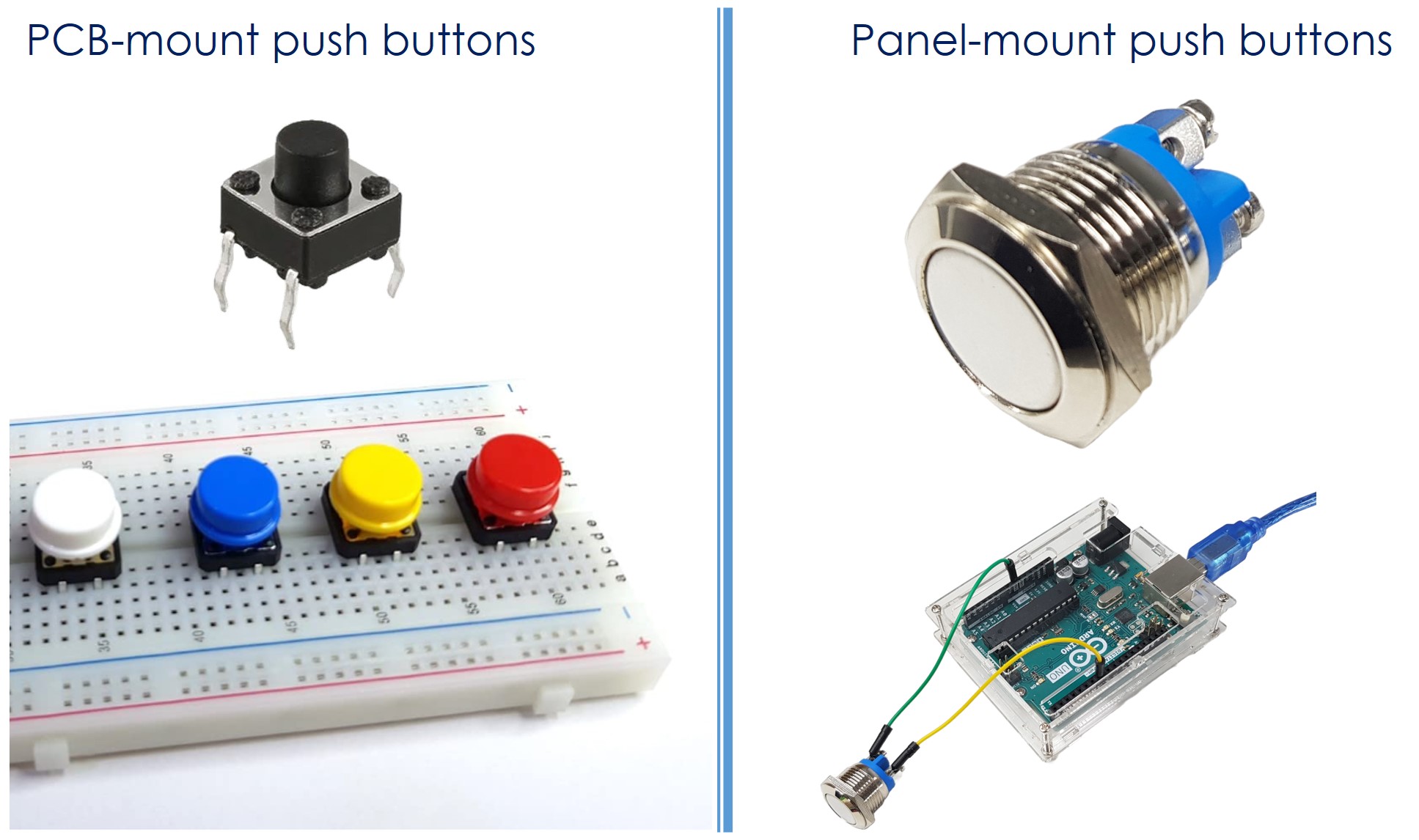
A push button, also known as a pushbutton, tactile button, or momentary switch, is a switch that closes when you press and hold it, and opens when you let go. There are many kinds of push buttons, usually divided into two groups:
- PCB-mount push buttons (suitable for breadboard mounting)
- Panel-mount push buttons
Button Pinout
PCB-Mount Buttons (4-Pin Breadboard Buttons)
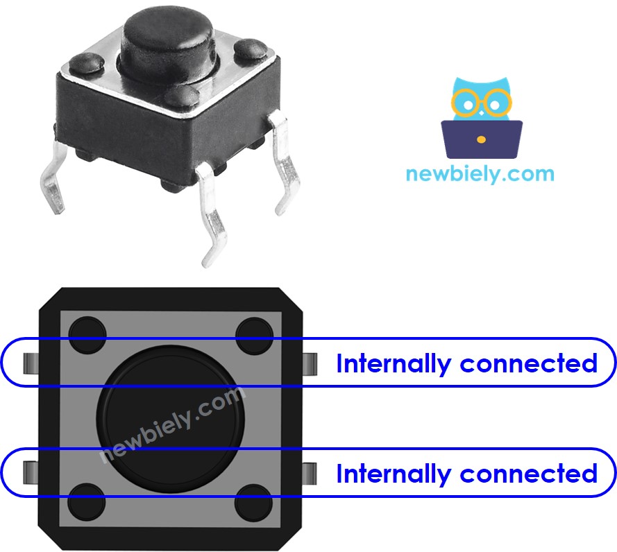
Most breadboard-friendly tactile buttons have four pins arranged in pairs. Here's the critical detail: Pins are internally connected in pairs!
- Pin layout: Opposite pins (across the button) are always connected internally
- Usage: You only need two pins that are NOT directly connected—typically one from each side
- Why four pins? Mechanical stability! When you press a button, you apply force. Four pins distribute that force, preventing the button from tilting or popping out of the breadboard/PCB.
Valid Connection Combinations:
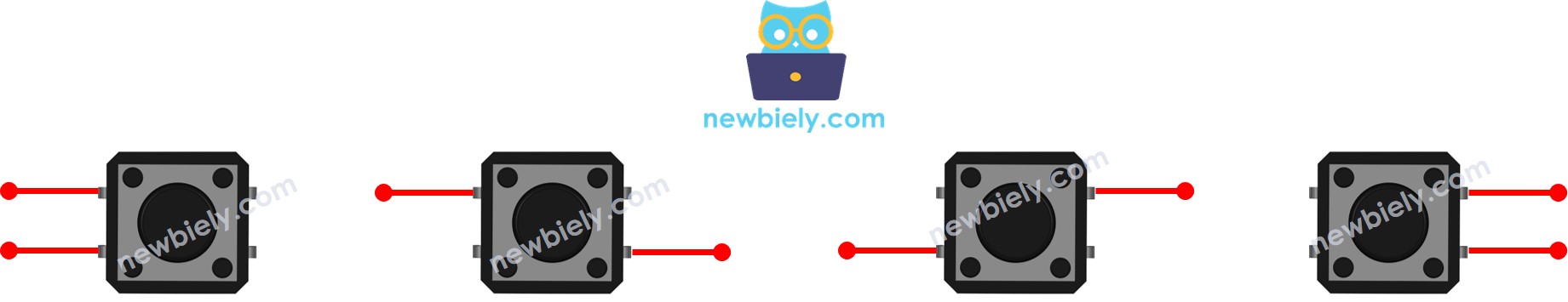
There are four possible ways to choose two pins, but due to symmetry, only two unique electrical configurations exist. We'll refer to properly selected pins as Pin A and Pin B (not internally connected).
Testing Your Button: Unsure which pins are connected? Use a multimeter in continuity mode. Test all six possible pin combinations to identify which pairs are always connected (avoid these pairs) and which connect only when pressed (use these).
Panel-Mount Buttons (2-Pin Buttons)
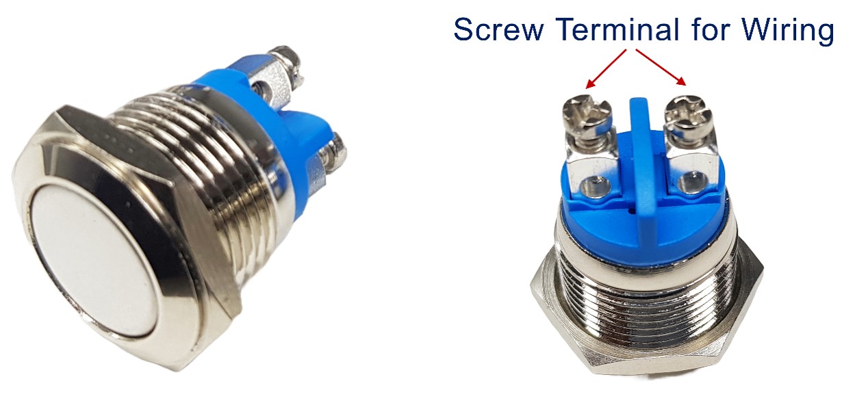
These industrial-style buttons feature just two terminals, making wiring straightforward. No confusing pin pairs—just two contacts that connect when pressed. Perfect for permanent installations where you're not using a breadboard.
Button Modules (3-Pin Smart Buttons)
Button modules are beginner-friendly pre-built circuits featuring:
- GND: Connect to Arduino ground
- VCC: Connect to 3.3V or 5V power (check module specs)
- OUT: Digital output signal to Arduino input pin
Built-in intelligence: These modules include a pull-down resistor already soldered on the PCB! Output is LOW when not pressed, HIGH when pressed—no external resistor required. They also often include debouncing circuits and LED indicators.
Trade-off: Modules are more expensive and take up more space, but they're perfect for learning without worrying about resistor calculations.
How Buttons Work (The Mechanics)
Buttons are simple mechanical switches with two states:
- Button RELEASED (default): Pin A and Pin B are physically separated by an air gap—no electrical connection exists. Open circuit.
- Button PRESSED: Internal spring mechanism forces metal contacts together, creating an electrical connection. Pin A connects to Pin B. Closed circuit.
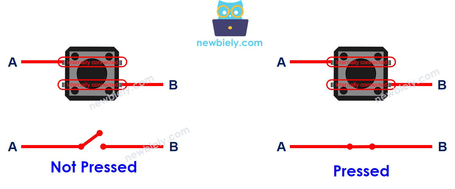
Key Insight: The button doesn't generate voltage or signals—it's purely a mechanical switch. Think of it like a drawbridge: down (pressed) = traffic flows, up (released) = traffic stops. The Arduino provides the voltage; the button just controls whether it flows or not.
Arduino MKR WiFi 1010 - Button Integration
To read button presses, we connect the button between an Arduino digital input pin and a voltage rail (VCC or GND). The Arduino's digitalRead() function then reports whether the button is pressed or released.
Basic Circuit:
- One button pin → Arduino digital input pin (e.g., D2)
- Other button pin → VCC (3.3V) or GND (0V)
The challenge? When the button is NOT pressed, the input pin is floating (connected to nothing), causing unreliable readings. We solve this with resistors.
Input State vs. Pressing State (The Resistor Relationship)
The relationship between physical button state (pressed/released) and electrical pin state (HIGH/LOW) depends on your wiring configuration and resistor choice. There are two standard methods:
Method 1: Pull-Down Resistor Configuration (Button to VCC)
Wiring:
- Button pin 1 → Arduino digital input pin
- Button pin 2 → VCC (3.3V power)
- Pull-down resistor (10kΩ) → Between input pin and GND
Logic:
- Button NOT pressed → Resistor pulls input LOW (0V) → digitalRead() returns LOW
- Button PRESSED → Input connects to VCC (3.3V) → digitalRead() returns HIGH
Behavior: Pressed = HIGH, Released = LOW (intuitive)
Method 2: Pull-Up Resistor Configuration (Button to GND)
Wiring:
- Button pin 1 → Arduino digital input pin
- Button pin 2 → GND (0V ground)
- Pull-up resistor (10kΩ) → Between input pin and VCC
Logic:
- Button NOT pressed → Resistor pulls input HIGH (3.3V) → digitalRead() returns HIGH
- Button PRESSED → Input connects to GND (0V) → digitalRead() returns LOW
Behavior: Pressed = LOW, Released = HIGH (inverted logic)
※ NOTE THAT:
Why Resistors Are Mandatory
Without a pull-up or pull-down resistor, the input pin becomes electrically floating when the button is released. Floating pins:
- Act like antennas, picking up electromagnetic noise
- Read random HIGH/LOW values (completely unpredictable)
- Cause erratic behavior—LEDs flickering, counters incrementing randomly, etc.
- Can even change readings when you wave your hand near the circuit!
Analogy: Imagine a light switch that's neither fully ON nor fully OFF—it flickers randomly depending on nearby interference. Resistors "pull" the switch to a definite position.
Recommended Approach for Beginners
The Arduino MKR WiFi 1010 has built-in pull-up resistors on every digital pin! Enable them in code with:
Advantages:
- No external components needed—just the button!
- Simpler wiring—fewer connections to mess up
- Cost savings—no need to buy resistors
- Reliable—internal resistors are well-matched to Arduino specs
Configuration: Button between input pin and GND. Use inverted logic (pressed = LOW).
This tutorial uses INPUT_PULLUP for simplicity. All code examples reflect this approach.
Wiring Diagrams
These diagrams show the recommended pull-up resistor configuration (button to GND, internal pull-up enabled in code).
PCB-Mount Button (Breadboard-Friendly)
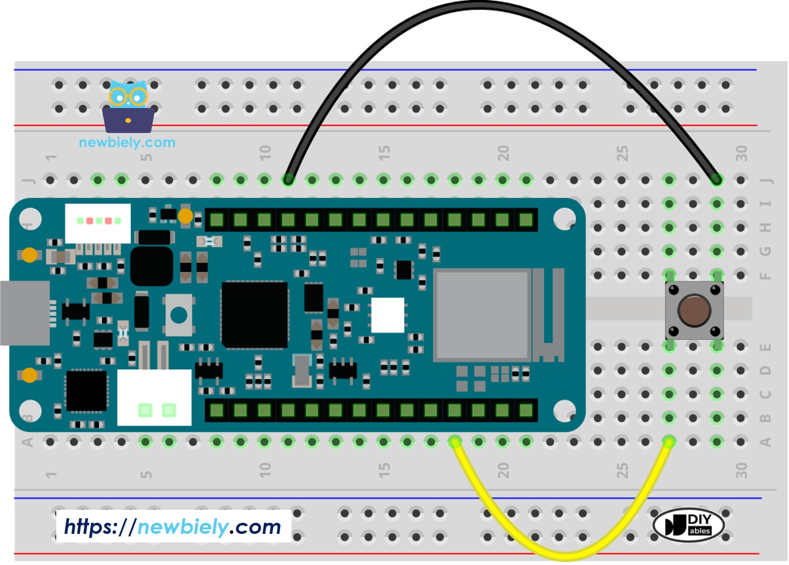
This image is created using Fritzing. Click to enlarge image
Connections:
- Button pin (one side) → Arduino digital pin D2
- Button pin (opposite side) → Arduino GND
- No external resistor needed—internal pull-up used!
Remember: Use pins that are NOT internally connected (opposite corners of the button).
Panel-Mount Button (2-Pin)
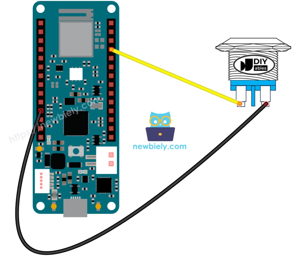
This image is created using Fritzing. Click to enlarge image
Connections:
- Button terminal 1 → Arduino digital pin D2
- Button terminal 2 → Arduino GND
- Internal pull-up configured in code
Pro Tip: Panel-mount buttons are ideal for enclosure-mounted controls. Drill a hole in your project box and secure the button with its included nut.
Arduino MKR WiFi 1010 Code
Detailed Instructions
New to Arduino MKR WiFi 1010? Complete our Getting Started with Arduino MKR WiFi 1010 tutorial first to set up your development environment.
- Connect the components to the Arduino MKR WiFi 1010 board as depicted in the diagram
- Plug your Arduino MKR WiFi 1010 into your computer's USB port
- Launch the Arduino IDE on your computer
- Select the Arduino MKR WiFi 1010 board and its COM port
- Copy the following code and paste it into the Arduino IDE.
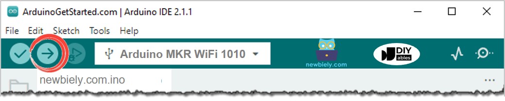
- Click the Upload button in the Arduino IDE to build your program and send it to your Arduino MKR WiFi 1010 board.
- Open the Serial Monitor in the Arduino software.
- Press and let go of the button several times.
- Look at the output on the Serial Monitor. It should look like what is shown below.
1 means high, and 0 means low.
Line-by-line Code Explanation
The Arduino MKR WiFi 1010 code above shows an explanation for each line. Please look at the comments in the code!
Modifying Arduino MKR WiFi 1010 Code
Let's change the code so it can see when something is pressed and let go.
Detailed Instructions
- Change the code as shown below.
- Click the Upload button on the Arduino IDE to compile and send the code to the Arduino MKR WiFi 1010 board.
- Open the Serial Monitor in the Arduino IDE.
- Press and then release the button.
- Look at the result on the Serial Monitor. It should look like the image below.
※ NOTE THAT:
The Serial Monitor might show several press and release messages even if you only pressed and released the button once. This is normal and is known as the chattering phenomenon. In some projects, you need a way to remove this extra information. You can find out more in the Arduino MKR WiFi 1010 - Button Debounce tutorial.
To keep things simple for beginners, especially when using several buttons, we made a library called ezButton. You can learn more about it here: https://arduinogetstarted.com/tutorials/arduino-button-library.
When using the button module, set the pin as an input by using pinMode(BUTTON_PIN, INPUT). The module gives a LOW signal when not pressed and a HIGH signal when pressed.
Video Tutorial
Additional Knowledge
When should I use a pull-down or pull-up resistor, and when should I not?
- SHOULD: When a sensor has two conditions—closed or open—you need to add a pull-up or pull-down resistor. This resistor helps change the conditions into two clear levels: LOW and HIGH. Examples include push-buttons, switches, and magnetic door sensors.
- SHOULD NOT: When the sensor already gives two clear voltage levels (LOW and HIGH), you do not need a pull-up or pull-down resistor. Examples include motion sensors and touch sensors.