Arduino MKR WiFi 1010 - Control Pump
Learn to control 12V water pumps with your Arduino MKR WiFi 1010! Master relay-based pump switching to build automated watering systems, aquarium controllers, cocktail makers, and fluid management projects. This fundamental tutorial teaches safe high-power pump control—essential for any liquid-handling automation.
What You'll Learn:
- Safe relay-based control of 12V submersible pumps
- Proper power distribution for pump circuits
- Programming timed pump activation cycles
- Foundation for sensor-triggered pumping systems
Real-World Applications:
- Automatic plant watering: Moisture sensor triggers pump for irrigation
- Aquarium systems: Timed water changes, filter circulation
- Cocktail/beverage makers: Precise liquid dispensing
- Coffee machines: Automated brewing cycles
- Hydroponics: Nutrient solution circulation
- Lab automation: Chemical reagent dosing
- Water features: Fountain control, waterfall pumps
- Cooling systems: Liquid cooling loop management
Safety Note: Always use submersible pumps rated for your liquid (water pumps for water only!). Never run pumps dry—they require liquid for cooling and lubrication.
Tutorial Scope: This guide covers basic ON/OFF timing. For advanced sensor-triggered pumping (moisture-based watering, level-controlled filling), see our project tutorials listed at the end.
Hardware Preparation
| 1 | × | Arduino MKR WiFi 1010 | |
| 1 | × | Micro USB Cable | |
| 1 | × | Relay | |
| 1 | × | 12V Pump | |
| 1 | × | Vinyl Tube | |
| 1 | × | 12V Power Adapter | |
| 1 | × | Breadboard | |
| 1 | × | Jumper Wires | |
| 1 | × | Optionally, DC Power Jack |
Or you can buy the following kits:
| 1 | × | DIYables Sensor Kit (18 sensors/displays) |
Additionally, some of these links are for products from our own brand, DIYables .
Overview of 12V Submersible Pumps
12V DC submersible pumps are compact, low-voltage water pumps designed for Arduino projects. Understanding their specifications ensures reliable operation and proper power system design.
Pump Pinout and Specifications
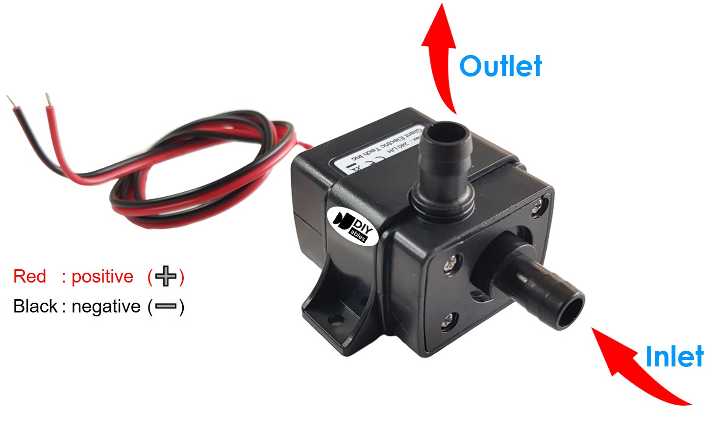
Electrical Connections:
- Red wire (+) - Positive terminal:
- Connects to +12V of DC power supply
- Polarity-sensitive—reversing damages internal electronics!
- Black wire (-) - Negative terminal:
- Connects to GND (ground) of DC power supply
- Completes circuit for motor operation
- Voltage: Typically 12V DC (operating range: 9-13.5V)
- Current draw: 0.5-2A depending on pump size and load
- Flow rate: 2-6 liters/minute (L/min) or 120-360 L/hour
- Max head height: 1-3 meters (vertical pumping capability)
- Power consumption: 6-24W typical
- Duty cycle: Some pumps require rest periods (check specs!)
- Submersible design: Must be submerged in liquid for cooling—running dry damages seals and motor
- Water only: Use water-rated pumps for water; chemical pumps for other liquids
- Inlet filter: Keep inlet screen clean to maintain flow rate and prevent clogging
- Priming: Some pumps need priming (filling tubing before operation) to start pumping
- Voltage incompatibility: Pump requires 12V; Arduino pins output only 3.3V
- Current demand: Pumps draw 0.5-2A; Arduino pins supply maximum 15mA
- Electrical isolation: Keeps high-power pump circuit separate from Arduino logic
- Fail to start the pump (insufficient voltage)
- Overload and destroy the Arduino pin (excessive current)
- Risk damaging the entire Arduino board
- Arduino sends LOW signal → Relay coil deactivated → Relay contacts open → Pump OFF (no 12V connection)
- Arduino sends HIGH signal → Relay coil activated → Relay contacts close → Pump ON (12V applied to pump)
- Low-power side: Arduino pin → Relay coil (3.3V, ~50mA)
- High-power side: 12V supply → Relay switch → Pump (12V, 0.5-2A)
- Coil voltage: 5V or 12V compatible with your Arduino setup
- Contact rating: Minimum 10A @ 12V DC (safety margin above pump current)
- Example: SRD-05VDC-SL-C relay (10A contact rating) works perfectly
- Relay pinout and electromagnetic operation principles
- How coils control switch contacts
- Wiring diagrams for NO (Normally Open) and NC (Normally Closed) configurations
- Programming relay control with digitalWrite()
- Selecting appropriate relay ratings
- Troubleshooting common relay issues
Key Specifications (check your pump's label/datasheet):
Important Notes:
How to Control Pump with Arduino MKR WiFi 1010
Direct Power Operation: Connect 12V power supply directly to pump → Pump runs continuously at full speed.
Arduino-Controlled Operation: We need a relay as an electronic switch.
Why Relay Control is Necessary:
Direct connection would:
The Relay Solution:
The relay acts as an electrically-isolated switch controlled by low-power Arduino signals:
Control Circuit:
Relay Selection: Choose relay rated for at least:
Not Familiar with Relays? Our Arduino MKR WiFi 1010 - Relay tutorial provides comprehensive coverage:
Master those concepts first, then return here to apply them to pump control!
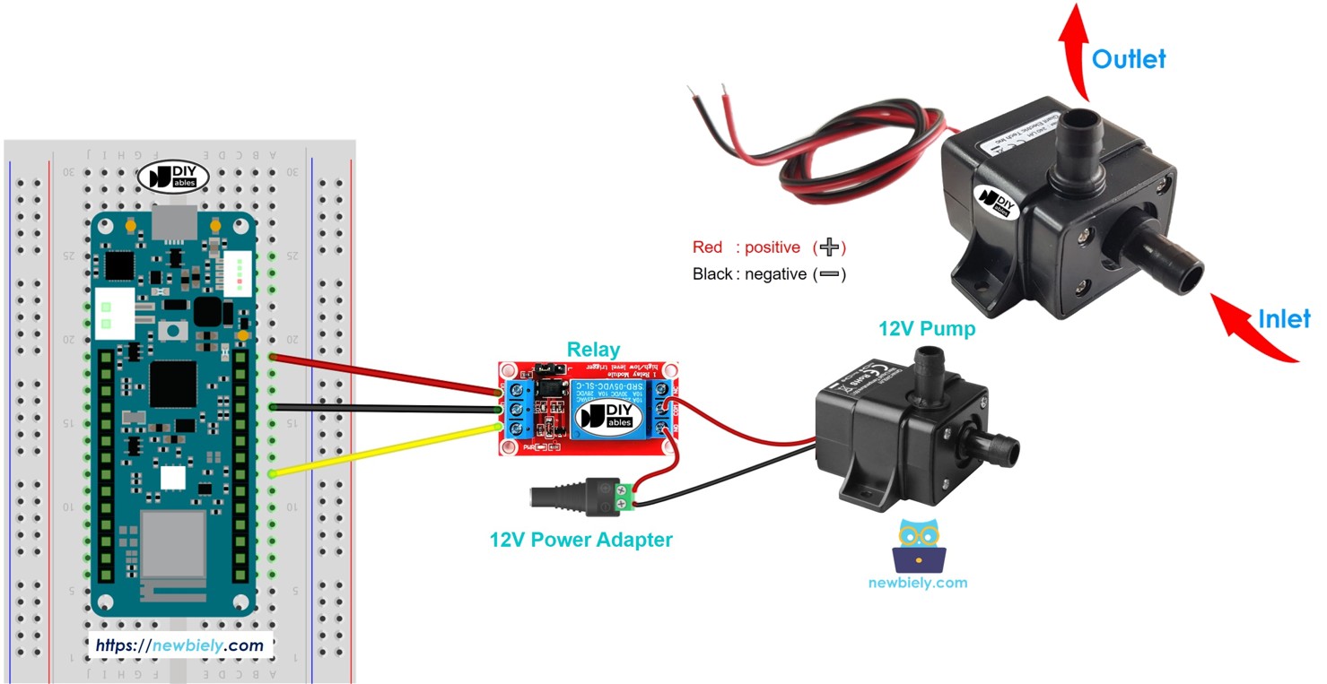
Wiring Diagram between Arduino MKR WiFi 1010, Relay and Pump
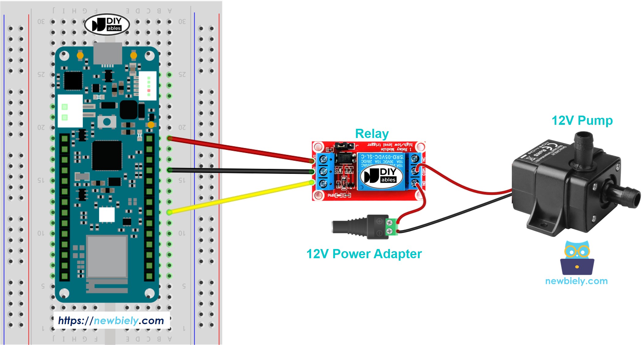
This image is created using Fritzing. Click to enlarge image
Arduino MKR WiFi 1010 - Pump Code
The code below turns the pump on and off every 4 seconds.
Detailed Instructions
New to Arduino MKR WiFi 1010? Complete our Getting Started with Arduino MKR WiFi 1010 tutorial first to set up your development environment.
- Connect the components to the Arduino MKR WiFi 1010 board as depicted in the diagram
- Plug your Arduino MKR WiFi 1010 into your computer's USB port
- Launch the Arduino IDE on your computer
- Select the Arduino MKR WiFi 1010 board and its COM port
- Copy the above code and paste it into the Arduino IDE.
- Compile and upload the code to the Arduino MKR WiFi 1010 board by clicking the Upload button in the Arduino IDE.
- Check the pump’s status.
Line-by-line Code Explanation
The Arduino MKR WiFi 1010 code above explains each line. Please read the comments in the code!